Advertisement
Quick Links
Advertisement

Related Manuals for FUFU & GAGA KF250008-01


Summary of Contents for FUFU & GAGA KF250008-01
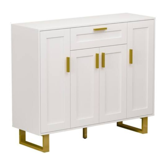
- Page 1 Shoe cabinet Version:10/09/2022 1/21...
- Page 2 2/21...
- Page 3 C x 4 A x 28 B x 24 D x60 E x 5 M6 x 40 mm 15 x 12 mm M3.5 x 40 mm M3.5 x 14 mm M4 x 20 mm G x 4 F x 32 H x 4 I x 4 J x 2...
- Page 4 4/21...
- Page 5 5/21...
- Page 6 L x 1 D x 4 I x 4 M3.5 x 14 mm M6 x 25 mm M3.5 x 14 mm M3.5 x 40 mm Fix No.23 leg support to No.2 plate using screw(D), rotate part(L) into No.23 as shown. Fix No.22 leg to No.2 plate with screw(I) as shown.
- Page 7 A x 8 M6 x 40 mm Insert quickfit screw(A) into corresponding holes in No.2 plate with a screwdriver as shown. D x 2 J x 1 M3.5 x 14 mm M3.5 x 14 mm M3.5 x 40 mm Separate glide into two parts at first. Fix slide rail(J1) to No.5 plate with screw(D) as shown.
- Page 8 D x 2 J x 1 M3.5 x 14 mm M3.5 x 14 mm M3.5 x 40 mm Fix slide rail(J1) to No.6 plate with screw(D) as shown. A x 8 M6 x 40 mm Insert quickfit screw(A) into corresponding holes in No.5 and No.6 plate with a screwdriver as shown.
- Page 9 B x 8 15 x 12 mm 15 x 12 mm 12 x 10 mm Connect No.5 and No.6 plate with No.7 and No.8, then turn cam lock(B) in No.7,8 plate clockwise to tighten as shown. Slide No.9 plate into slots between No.5 and No.6 plate as shown. 9/21...
- Page 10 B x 4 15 x 12 mm 15 x 12 mm 12 x 10 mm Attach the component to No.2 plate, then turn cam lock(B) in No.5,6 plate clockwise to tighten as shown. 10/21...
- Page 11 B x 4 15 x 12 mm 15 x 12 mm 12 x 10 mm Attach No.3 and No.4 to No.2 plate, then turn cam lock(B) in No.3,4 plate clockwise to tighten as shown. Slide No.9 and No.10 plate into available slots as shown. 11/21...
- Page 12 A x 8 B x 8 F x 32 M6 x 40 mm 15 x 12 mm 15 x 12 mm 12 x 10 mm Insert quickfit screw(A) into corresponding holes in No.1 plate with a screwdriver as shown. Cover No.1 plate to the top, then turn cam lock(B) in No.3,4,5,6 plate clockwise to tighten as shown.
- Page 13 Place No.11 and No.12 shelf in. G x 4 D x 8 E x 2 M3.5 x 14 mm M4 x 20 mm M3.5 x 14 mm M3.5 x 40 mm Fix hinge(G) to No.18 and No.19 plate respectively with screw(D) as shown.
- Page 14 H x 4 D x 8 E x 2 M3.5 x 14 mm M4 x 20 mm M3.5 x 14 mm M3.5 x 40 mm Fix hinge(H) to No.20 and No.21 plate respectively with screw(D) as shown. Fix handle(E1) using screw(E2) as shown.
- Page 15 A x 4 K x 4 M6 x 40 mm 12 x 10 mm 15 x 12 mm 12 x 10 mm Insert quickfit screw(A) into No.13 plate with a screwdriver at first. Attach No.14 and No.15 plate to No.13, turn cam lock(K) clockwise to tighten as shown.
- Page 16 C x 4 M3.5 x 40 mm M3.5 x 14 mm M3.5 x 40 mm Attach No.16 plate and fix with No.14 and No.15 using screw(C) as shown. J x 2 D x 4 E x 1 M3.5 x 14 mm M4 x 20 mm M3.5 x 14 mm M3.5 x 40 mm...
- Page 17 Align rails, slide the drawer. M x 28 Reinforce back plate using part(M) as shown. 17/21...
- Page 18 N x 1 Install anti-tipping device(N) as shown. 18/21...
- Page 19 19/21...
- Page 20 WARRANTY WARRANTY CLAIMS •There is a 30-day warranty for broken furniture or any other problems that do not work properly. The warranty will start from the date of purchase which must be verified by proof of purchase. •Before making a claim, we may be able to answer your query, simply call us. Please leave your purchase order number, along with some details of the problem, if you want a replacement part.
- Page 21 RETURNS CHANGED YOUR MIND AND NEED TO RETURN YOU ITEM? PLEASE FOLLOW THE BELOW INSTRUCTIONS: •If you have purchased and have simply changed your mind, follow the retailer’s instructions for returns. DEFECTIVE ITEMS •If your item is defective in any way, i.e. it doesn’t work but you can’t identify why, in the first instance, please call us.
Need help?
Do you have a question about the KF250008-01 and is the answer not in the manual?
Questions and answers