
Related Manuals for Lauda LOOP 100


Summary of Contents for Lauda LOOP 100
- Page 1 Operation manual LOOP L 100, L 250 Thermo-electric circulation thermostat Read this manual prior to performing any task! V3REV1 3...
- Page 2 Manufacturer LAUDA DR. R. WOBSER GMBH & CO. KG Laudaplatz 1 97922 Lauda-Königshofen Germany Tel.: +49 (0)9343 503-0 Fax: +49 (0)9343 503-222 E-mail: info@lauda.de Internet: https://www.lauda.de Translation of the original operation manual Q4WA-E_13-001, 3, en_US 3/18/2022 ©LAUDA 2021 replaces issue V3R11/12, V2R6, V2R5, V2R3, V1R24, V1R22, V1R20...
-
Page 3: Table Of Contents
Overtemperature cutout and overtemperature...................... 14 RS 232 interface................................14 Commissioning..................................15 Set up and connect the hoses............................ 15 LAUDA heat transfer liquid............................16 Filling with heat transfer liquid and draining......................17 Establishing a mains connection..........................19 Operation.................................... 20 General safety instructions ............................20 LOOP menu structure.............................. - Page 4 Check the heat transfer liquid........................... 33 Cleaning the device..............................34 Technical data..................................35 General....................................37 Copyright..................................37 Technical changes................................ 37 Warranty conditions..............................37 Contact LAUDA................................. 37 Declaration of Conformity............................37 Product Returns and Clearance Declaration......................39 Index....................................40 4 / 41 LOOP...
-
Page 5: Safety
If you lose the operating manual, you can download a new one from our LAUDA homepage. When operating the device, there is a risk of injury from high and low tem- peratures, fire and the presence of electrical energy. These risks posed by the device have been mitigated in the design to the extent possible in keeping with the applicable norms. -
Page 6: Emc Requirements
Service work may only be performed by the LAUDA Service department or a service partner authorized by LAUDA. Materials All parts that come into contact with heat transfer liquid are manufactured from high-quality materials adapted to withstand the operating temperature. -
Page 7: Heat Transfer Liquid
Heat transfer liquid The device is designed exclusively for non-combustible heat transfer liq- uids according to class I as per DIN 12876-1. The use of heat transfer liquids poses a risk of injury from high and low temperatures if certain upper or lower temperature thresholds are exceeded or the external application is broken and a reaction is initiated with the heat transfer liquid. - Page 8 Warning A warning of "warning" indicates a possibly dangerous situation. If this warning is not observed, then death or severe, irreversible injury could occur. WARNING! Type and source Consequences of not following instructions Measure 1 Measure... Caution A warning of "caution"...
-
Page 9: Unpacking
Also notify LAUDA Service Temperature control devices immediately. You will find the contact information here Ä Chapter 8.4 “Contact LAUDA” on page 37. Table 2: Standard accessories for all devices Device type... -
Page 10: Setup And Operating Buttons
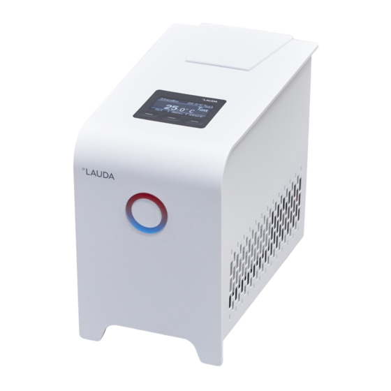
Setup and operating buttons Setup of the device Fig. 1: Front side LOOP Controller with temperature display and control buttons (soft buttons) Cover over the tank lid Ventilation openings 4 feet 10 / 41 LOOP... - Page 11 Fig. 2: Rear LOOP L 100 Pump connection IN inlet (back from consumer) Pump connection OUT outflow (to consumer) RS 232 interface (socket) Device panel plug Box for 2 safety fuses Mains switch Rating label LOOP 11 / 41...
- Page 12 Fig. 3: Rear LOOP L 250 Pump connection OUT outflow (to consumer) Pump connection IN inlet (back from consumer) RS 232 interface (socket) Device panel plug Box for 2 safety fuses Mains switch Rating label Fig. 4: Tank with filler nozzle and cover Fig.
-
Page 13: Mains Switch
LOOP 100 LOOP 250 Fig. 6: Ventilator fan (1) on the underside The device sucks up fresh air from below! Mains switch The mains switch can be set to the following positions: Position [I] switches the device on. Position [O] switches the device off. -
Page 14: Operating Buttons
Operating buttons The three operating buttons can be used to control the functions of the device. Use the [Set] button to configure the set temperature. Use the [Menu] button to pull up the menu, in order to configure set- ... -
Page 15: Commissioning
Commissioning Set up and connect the hoses WARNING! Danger of device falling or overturning Crushing, impacts Do not tilt the device. Position the device on an even, non-slip surface with a suf- ficient load carrying capacity. Do not position the device close to table edges. ... -
Page 16: Lauda Heat Transfer Liquid
LAUDA heat transfer liquid Note the following instructions: The heat transfer liquids each cover a recommended temperature range and must be suitable for the temperature range associated with their application. Never use contaminated or degenerated heat transfer liquids. ... -
Page 17: Filling With Heat Transfer Liquid And Draining
Note the following instructions: The device is designed exclusively for non-flammable heat transfer liq- uids. LAUDA is not liable for damages resulting from the use of unsuitable heat transfer liquids. Only connect pressure-sealed consumers to the device. ... - Page 18 The tank is ventilated through the tank lid. Once the device is filled, do not tip it and never set it upside down! Empty the device before transporting it. Filling the tank Slide and remove the cover over the filler nozzle towards the back of the device.
-
Page 19: Establishing A Mains Connection
Establishing a mains connection NOTICE! Use of impermissible mains voltage or mains frequency Device damage Compare the type plate with the available mains voltage and mains frequency. Take the following information into account: Only use the supplied power cable for the power supply. ... -
Page 20: Operation
Operation General safety instructions CAUTION! Risk of heat transfer liquid escaping during operation due to open consuming unit Scalding, cold burns Always use hydraulically sealed consuming units. CAUTION! Risk of heat transfer liquid escaping due to the use of unsuitable hoses Scalding, cold burns The temperature and media resistance of the hoses must be... -
Page 21: Loop Menu Structure
LOOP menu structure Fig. 10: Menu structure LOOP 21 / 41... -
Page 22: Set The Set Temperature T
Set the set temperature T The set temperature T is the temperature that the constant temperature equipment should reach and then maintain. is the outflow temperature of the device. In a well-controlled system, the outflow temperature is the same as the set temperature. -
Page 23: Edit Basic Settings
Select the Menu Setup Limits Lower limit (Til) menu item. Enter the temperature limit value. Press [OK] to confirm the new value. Edit basic settings This chapter explains the basic settings. Set temperature unit: Degrees Celsius or degrees Fahrenheit. ... - Page 24 If a temperature deviation is discovered during inspection of the device with a reference thermometer, the offset value (that’s the additive part of the char- acteristic line) of the internal measurement chain can be adjusted or a 2- point calibration carried out with the menu item Calibration . The reference thermometer must, in accordance with the requirements of the calibration certificate, be incorporated into the outflow of the device.
-
Page 25: Restore Factory Setting
Restore factory setting Use this menu item to restore the factory settings in the device. With All default the control parameters, internal Pt1000, and other parameters are reset to factory settings. With Control parameter only the control parameters are reset to the ... -
Page 26: Control
5.10 Control 5.10.1 Control basics Definition A brief explanation of terms Actuating - Initial value of the controller to compensate for the differ- signal ence between the actual value and target value (control deviation). PID con- - The PID controller operates with extreme speed and preci- troller sion and consists of a P, I and D-component. - Page 27 If the Xp parameter selected is too large, the actual value will reach the pro- portional range early and the P-component will be less than 100 % of the actuating signal. It takes longer to reach the target value and as a result, the simultaneously integrated I-component has more time to establish its actuating signal component.
-
Page 28: Overview Of Control Parameters
The actual value increases relatively sharply towards the specified target value. The proportional area settings seem to be correct. If the control devia- tion becomes smaller, the actual value approaches the target value much more slowly. The integration component (I-component) must compensate for the drastic reduction of the proportional component (P-component). -
Page 29: Rs 232 Interface
5.11 RS 232 interface 5.11.1 Cable and test of the RS 232 interface Computer Thermostat Signal 9-pin sub-D socket 25-pin sub-D socket 9-pin sub-D socket Signal With hard- Without With hard- Without With hard- Without ware hand- hardware ware hand- hardware ware hand- hardware... -
Page 30: Write Commands
The command from the computer must be made with a CR, CRLF, or LFCR. CR = Carriage Return (Hex: 0D); LF = Line Feed (Hex: 0A) The response from the thermostat is always made with a CRLF. After each command sent to the thermostat, it is necessary to wait for ... -
Page 31: Read Commands
5.11.4 Read commands Read commands are data demands from the PC to the thermostat. Command Description IN_PV_00 Query outflow temperature IN_SP_00 Query set temperature IN_SP_04 Query of outflow temperature limit Hi IN_SP_05 Query of outflow temperature limit Lo IN_PAR_00 Query of the control parameter Xp IN_PAR_01 Query of the control parameter Tn (181 = OFF) IN_PAR_02... - Page 32 Error Description ERR_5 Syntax error in value ERR_6 Impermissible value The upper temperature limit is lower than or equal to the lower temperature ERR_32 limit. 32 / 41 LOOP...
-
Page 33: Maintenance
Maintenance General safety instructions DANGER! Contact with live or moving parts Electric shock, impacts, cutting, crushing The device must be disconnected from the mains power supply before any kind of maintenance is performed. Only skilled personnel are permitted to perform repairs. ... -
Page 34: Cleaning The Device
If you are unsure whether decontaminants or cleaning agents are com- patible with parts of the device or the materials contained in those parts, please contact LAUDA Service Temperature control devices. 34 / 41 LOOP... -
Page 35: Technical Data
Technical data The information has been conveyed in accordance with DIN 12876. Specification Unit LOOP 100 LOOP 250 Working temperature range °C 4 – 80 Temperature stability ±0.1 Ambient temperature range °C 5 – 40 Storage temperature °C 5 – 40 Power supply 100 –... - Page 36 Specification Unit LOOP 100 LOOP 250 Protection level according to DIN EN 61140 Safety fuse 2 pieces SP 5x20 F 250V 6.3A H (EES 074) Device dimensions ‑ Width ‑ Depth ‑ Height Weight 11.9 Noise level (1m) dB(A) *Measured at 100 % setting [Fan Limit] Ä Chapter 5.6 “Edit basic settings”...
-
Page 37: General
Technical changes The manufacturer reserves the right to make technical modifications to the device. Warranty conditions LAUDA grants a standard warranty of one year on all devices. Contact LAUDA Contact the LAUDA Service department in the following cases: Troubleshooting ... - Page 38 EC DECLARATION OF CONFORMITY Manufacturer: LAUDA DR. R. WOBSER GMBH & CO. KG Laudaplatz 1, 97922 Lauda-Königshofen, Germany We hereby declare under our sole responsibility that the machines described below Product Line: LOOP Serial number: from S210000001 Types: LOOP L 100, LOOP L 250...
-
Page 39: Product Returns And Clearance Declaration
Product Returns and Clearance Declaration Product Returns Would you like to return a LAUDA product you have purchased to LAUDA? For the return of goods, e.g. for repair or due to a complaint, you will need the approval of LAUDA in the form of a Return Material Authorization (RMA) or processing number. -
Page 40: Index
Cleaning ......34 LAUDA heat transfer liquids ....16 Decontamination . - Page 41 Limit Fan ....... . . 23 Tank Lock Cover ....... . 17 Buttons .
- Page 44 LAUDA DR. R. WOBSER GMBH & CO. KG ◦ Laudaplatz 1 ◦ 97922 Lauda-Königshofen Tel.: +49 (0)9343 503-0 ◦ Fax: +49 (0)9343 503-222 E-mail: info@lauda.de ◦ Internet: https://www.lauda.de...
Need help?
Do you have a question about the LOOP 100 and is the answer not in the manual?
Questions and answers