
Subscribe to Our Youtube Channel
Related Manuals for ZIEHL-ABEGG ECblue RE Series


Summary of Contents for ZIEHL-ABEGG ECblue RE Series
- Page 1 english ECblue Application Cleanroom EC-fans and motors with highest efficiency Assembly instructions Motor size B (IP20) Keep for reference! L-BAL-F056-GB 2022/45 Index 005 Part.-No. 00700562-GB...
-
Page 2: Table Of Contents
Assembly instructions ECblue Content General notes ..........Validity . - Page 3 Assembly instructions ECblue Mounting the motor ........Electrical installation .
- Page 4 Assembly instructions ECblue Service note ........L-BAL-F056-GB 2022/45 Index 005 Part.-No.
-
Page 5: General Notes
Assembly instructions ECblue General notes 1 General notes Compliance with the following instructions is mandatory to ensure the functionality and safety of the product. If the following instructions given especially but not limited for general safety, transport, storage, mounting, operating conditions, start-up, mainte- nance, repair, cleaning and disposal / recycling are not observed, the product may not operate safely and may cause a hazard to the life and limb of users and third parties. -
Page 6: Exclusion Of Liability
We do not accept any liability for possible errors or omissions in the information con- tained in data, illustrations or drawings provided. ZIEHL-ABEGG SE is not liable for damage due to misuse, improper use or as a consequence of unauthorized repairs or modifications. -
Page 7: Explanations Of Symbols
Assembly instructions ECblue Safety instructions • Operation of plug fans outside devices. • Connect built-in fans to open flue pipes of gas and other firing devices. • Use of the fan and add-on parts (e.g. guard grille) as a resting surface or climbing aid. –... -
Page 8: Product Safety
Assembly instructions ECblue Safety instructions 2.4 Product safety The device conforms to the state of the art at the time of delivery and is fundamentally considered to be reliable. The device and its accessories must only be used in a flawless condition and installed and operated in compliance with the assembly instructions and/or operating instructions. -
Page 9: Modifications / Interventions In The Device
ZIEHL-ABEGG.These parts were specifically designed for the device. There is no guarantee that parts from non-original sources are designed and manufactured in correspondence with load and safety requirements. Parts and optional equipment not supplied by ZIEHL-ABEGG are not approved by ZIEHL-ABEGG for use. 2.8 Operator’s obligation of diligence •... -
Page 10: Employment Of External Personnel
The fans may not be operated until they are installed in line with their intended use. The supplied and certified guard grille of ZIEHL-ABEGG SE fans is designed in accordance with DIN EN ISO 13857 Table 4 (from the age of 14 up). In the event of deviations, further structural protective measures must be taken for safe operation. -
Page 11: Temperature Management
3.4 Note on the ErP directive ZIEHL-ABEGG SE wishes to point out that, based on the directive (EU) no. 327/2011 of the Commission of 30th of March 2011 for enforcing directive 2009/125/EC (hereinafter referred to as ErP directive), the operational area of certain fans within the EU is bound by certain prerequisites. -
Page 12: Disposal / Recycling
Assembly instructions ECblue Mounting • Store the fan / motor in the original packaging in a dry area protected from the weather and protect it from dirt and weather until final installation. • Avoid prolonged storage; we recommend a maximum of one year (consult the manufacturer before starting if stored for longer). -
Page 13: Connection Cable & Junction Box
Assembly instructions ECblue Mounting • Lift the fan out of the packaging with a lifting gear (lifting beam). Attachment points are solely the holes on the housing flange, motor bed, support plate, motor suspensions, fastening brackets and any crane eyes of the fan (depending on the design of the fan). •... -
Page 14: Version With Separate Junction Box
Assembly instructions ECblue Mounting 4.3 Version with separate junction box For products supplied by ZIEHL-ABEGG with a separate junction box, note the following information. 1 Separate junction box made of plastic or metal Lid screws Tightening torque: Plastic box 1.3 Nm/12 Lb In, metal box 2.6 Nm/23 Lb In... -
Page 15: Mounting Of Centrifugal Fans
Assembly instructions ECblue Mounting 4.6 Mounting of centrifugal fans 4.6.1 Mounting of centrifugal fans design RE, RH, RZ For attachment to fixed motor flange use screws with property class 8.8 to EN ISO 4014 and provide with suitable screw locking. Permissible tightening torques M Thread size Property class 8.8, friction coefcient µges = 0.12... -
Page 16: Erecting The Equipment: Design Er
Assembly instructions ECblue Mounting Attention! • Avoid structural damage or stress with installation. Flange and mounting bracket must be fixed flat on a level surface. • Provide screwed connections with suitable screw locking. 4.6.3 Erecting the equipment: Design ER.. / GR.. / WR.. •... -
Page 17: Optimal Installation Distances According To For Rh
Assembly instructions ECblue Mounting Example for version with Optimizer The Optimizer can be removed temporarily for better accessibility (e.g. for laying of cables or cleaning). Depending on the version, the Optimizer is engaged or attached to the ventilation module with screws (tightening torque 5.4 Nm). 1 Optimizer Attention! An external mechanical stress on the Optimizer, e.g. -
Page 18: Mounting The Motor
• The max. permissible mass of the impeller ort he component to be driven must be inquired from and confirmed in writing by ZIEHL-ABEGG. • Motors are not balanced as standard, a complete balancing with mounted fan impeller is necessary. -
Page 19: Electrical Installation
Assembly instructions ECblue Electrical installation 5 Electrical installation 5.1 Safety precautions Danger due to electric current • Work on electric components may only be carried out by trained electricians or by persons instructed in electricity under the supervision of an electrician in accordance with electrical engineering regulations. -
Page 20: Connection
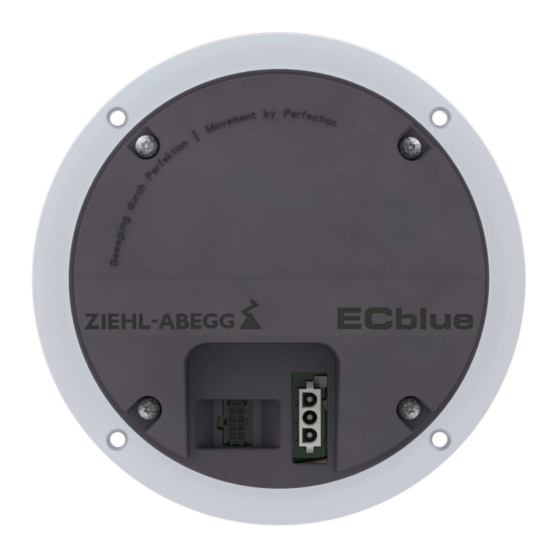
Assembly instructions ECblue Electrical installation 5.2 Connection Representation with standard connecting cables 07.11.2013 v_anschl_ecblue_baugr_b_ip20.vsd 1 Connection control (Molex-micro-fit 3.0 8-pole, 43045-43045) 2 Connection line (AMP 3-pole MATE-N-LOK, 350789-3) 3 Do not loosen the safety screws from the housing! Control: hose cable 8 x 0.14 mm (26 AWG) comparable LiYY-OB, length approx. -
Page 21: Accessories: Connection Box
Assembly instructions ECblue Electrical installation Information The respective connections are represented in the enclosure of this assembly instructions (see Connection diagram)! Connection to the terminals is only permissible with compatible counterparts! 5.3 Accessories: connection box A connection box is available as an accessory for the standard connecting cables, which enables the simple, quick and safe wiring of multiple fans. -
Page 22: Voltage Supply
Assembly instructions ECblue Electrical installation 5.5 Voltage supply 5.5.1 Mains voltage Danger due to electric current • It must be strictly observed that the line voltage complies with specified on the rating plate and lies within the allowable tolerance specifications (see technical data). •... -
Page 23: Systems With Residual Current Protective Devices
Assembly instructions ECblue Electrical installation 1 ~ types can be used in IT-System in standard version. These may only be used in 3 ~ IT-Systems if no higher voltage to the “PE” can occur than the specified mains voltage of the device even in case of a fault to earth of a mains phase which is not used by the device (of none of the two power supplies). -
Page 24: Connection Terminal Type A-G-247Nw For Service
Assembly instructions ECblue Electrical installation 5.9 Connection terminal type A-G-247NW for service If necessary an external terminal can be connected. This can be e.g. necessary to adapt the pre-setting during start-up. For information about the current operating condition a terminal can be permanent attached. The voltage supply of the terminal is made by the accumulators inserted there or the plug power supply unit. - Page 25 Assembly instructions ECblue Electrical installation Connection with RJ45 patch cable whe using the connection box for ECblue The connection is made at the terminals: A (D+), B (D-) und GND. The connection is made to the connection box by the RJ45 service connection. L-BAL-F056-GB 2022/45 Index 005 Part.-No.
-
Page 26: Communication
Assembly instructions ECblue Electrical installation 5.10 Communication 5.10.1 RS-485 interface for MODBUS The device comes equipped with a RS-485 interface for networking via MODBUS. Conntection at: “A (D+)”, “B (D-)” and “GND”. Addressing is performed by an external terminal or a PC with the appropriate software. Automatic addressing can be started when the connections “ID1”... - Page 27 Assembly instructions ECblue Electrical installation Example for MODBUS connection The data line must be conducted from one device to the next. No other type of wiring is allowed! Always use only two wires of one lead (twisted pair) for the connection. Recommended wire types 1.
-
Page 28: Modbus Networking And Automatic Addressing
Assembly instructions ECblue Electrical installation When using telephone cable with four cable cores, we recommend the following allocation: • A (D+) = red • B (D-) = black • ID1 - ID2 = yellow • GND = white Default interface parameter •... - Page 29 Assembly instructions ECblue Electrical installation Networking with telephone wire The connection at the terminal is made at the terminals: A (D+), B (D-) and GND. Connection of the users via the terminals: A (D+), B (D-), GND and ID1 / ID2 Networking with RJ45 patch cable by usage connection box for ECblue The connection to the terminal is made at the terminals: A (D+), B (1D-) and GND.
-
Page 30: Open-Collector Output "A1" (Status / Tacho)
Assembly instructions ECblue Electrical installation 5.11 Open-Collector output “A1” (status / tacho) Open-Collector pulse output for status display or speed display. Status display (function for factory setting) Depending on the operating state of the device, the output “A1” is 200...300 switched to GND potential for a certain number of pulses. -
Page 31: Commissioning
4. Check the system for resonances. If they lead to unacceptably high vibrations on the fan, the system must not be started up. 5. Fans from ZIEHL-ABEGG SE are delivered balanced in accordance with DIN ISO 21940-11 for the appropriate fan category in accordance with ISO 14694 Check the fan for mechanical vibrations after installation. -
Page 32: Diagnostics / Faults
Assembly instructions ECblue Diagnostics / Faults 7 Diagnostics / Faults 7.1 Trouble shooting Type of error Possible cause Remedial measures Fan does not Mains voltage failure Check mains voltage run (anymore) Failure of a phase Under - or overvoltage Earth fault Check the motor connection and mains voltage Coil closure Replace fan... -
Page 33: Indication Of The Operating Condition Over A1 And A2
Assembly instructions ECblue Diagnostics / Faults Type of error Possible cause Remedial measures unusual noises Bearing damaged / worn Change bearings In motor size 055“(Z” / “B” at cross flow) and 072 (O) change the fan. Impeller / blade drags / When indicated clear foreign bodies / dirt from the fan (see scrapes "Impeller blocked or dirty") - Page 34 Assembly instructions ECblue Diagnostics / Faults A1 Status Out A2 Operation Reaction of Controller Cause Out OC * Remedial measures Explanation off GND = ON off GND = ON Switch off by Bus No enable = OFF Description Communication ECblue MODBUS Temperature management active The device has an active temper- ature management to protect it from...
- Page 35 Assembly instructions ECblue Diagnostics / Faults A1 Status Out A2 Operation Reaction of Controller Cause Out OC * Remedial measures Explanation off GND = ON off GND = ON Intermediate overvoltage If the DC-link voltage drops below the limit within 75 seconds, If the DC-link voltage increases then the cotroller will attempt to above a specified limit, the motor...
-
Page 36: Behaviour In Rotation By Air Current In Reverse Direction
Assembly instructions ECblue Diagnostics / Faults A1 Status Out A2 Operation Reaction of Controller Cause Out OC * Remedial measures Explanation off GND = ON off GND = ON Error peak current After a switch off the controller waits for 5 seconds then the con- If the motor current increases troller attempt a start. -
Page 37: Service Work
Repair, e.g. by welding is prohibited! • Bolted-on impellers and/or wings may only be replaced by authorised ZIEHL-ABEGG SE staff. The manufacturer shall not be liable for damage caused through improper repair work. • Please consult our service department with regard to changing the bearing as for all other damage (e.g. -
Page 38: Cleaning
Assembly instructions ECblue Service work Information Confirmation number for inquiries or in service cases see rating plate. State the additionally engraved confirmation number (available depending on the motor build) if the rating plate is no longer legible. This can be found under the affixed rating plate or on the stator flange (in external rotor motors) depending on the motor size. -
Page 39: Enclosure
Assembly instructions ECblue Enclosure 9 Enclosure 9.1 Technical data Line voltage* 1 ~ 200...277 V, 50/60 Hz (see rating plate) (Versions for DC power supply on request) Maximal line fuse** 16 A Max. load limit integral of cut-in 3.0 A current approx. - Page 40 Assembly instructions ECblue Enclosure Ball bearing life The bearing service life of the motor-integrated ball bearings determined in accordance with the standard calculation method is largely determined by the grease service life F10h and is approx. 30,000 to 40,000 operating hours in standard use, taking into account a temperature and load spec- trum.
-
Page 41: Connection Diagram
Assembly instructions ECblue Enclosure 9.2 Connection diagram ECblue (_ _ _ _ _-_I_.B_._ _ _ _) A (D+) MODBUS (RS-485) Status Out OC A1 B (D-) MODBUS (RS-485) Operation Out OC A2 ID1 Addressing DC Out (I = 50 mA) 10 V ID2 Addressing GNYE Pin 1 = RD... -
Page 42: Ec Declaration Of Incorporation
(also with integrated EC controller) Complies with the requirements in Appendix I, Articles 1.1.2, 1.1.5, 1.4.1, 1.5.1 in EC Machinery Directive 2006/42/EC. Manufacturer: ZIEHL-ABEGG SE Heinz-Ziehl-Straße 74653 Künzelsau, Germany The following harmonized standards have been applied: EN 60204-1:2018 Safety of machinery –... - Page 43 Start-up of this incomplete machine is prohibited until it is ensured that the machine in which it has been installed complies with the provisions of the EC Machinery Directive. Künzelsau, 27.04.2022 (Location, date of issue) ZIEHL-ABEGG SE ZIEHL-ABEGG SE Tobias Gauss Moritz Krämer Deputy Head of Technics Ventilation...
-
Page 44: Manufacturer Reference
- ventilation technology. phone: +49 (0) 7940 16-800 Email: fan-controls-service@ziehl-abegg.de Our worldwide contacts are available in our subsidiaries for deliveries outside of Ger- many, see www.ziehl-abegg.com. L-BAL-F056-GB 2022/45 Index 005 Part.-No. 00700562-GB 44/44...
Need help?
Do you have a question about the ECblue RE Series and is the answer not in the manual?
Questions and answers