Advertisement
Quick Links
INSTALLATION AND MAINTENANCE INSTRUCTIONS
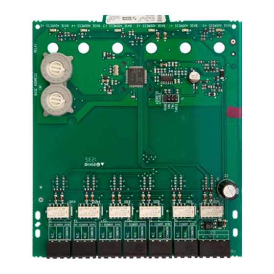
FIK-CR-6
Six Relay Control Module
SPECIFICATIONS
Normal Operating Voltage:
15-32 VDC Stand-By Current:1.90 mA @ 24V
Alarm Current:
32 mA (assumes all six relays have been switched once and all six LEDs solid on)
Temperature Range:
32°F to 120°F (0°C to 49°C)
Humidity:
10 to 93% Non-condensing
Dimensions:
6.8" H × 5.8" W × 1.0" D
Accessories:
FIK-BB-2 cabinet and chassis
Wire Gauge:
12-18 AWG
Relay Current:
30 mA/Relay Pulse (15.6 mS pulse duration) pulse under panel control
RELAY CONTACT RATINGS
CURRENT RATING
2 A
3 A
2 A
0.46 A
0.7 A
0.9 A
0.5 A
0.3 A
BEFORE INSTALLING
If the modules will be installed in an existing operational system, inform the
operator and local authority that the system will be temporarily out of service.
Disconnect the power to the control panel before installing the modules. This
system contains static sensitive components. Always ground yourself with a
proper wrist strap before handling any circuits so that static charges are re-
moved from the body. The housing cabinet should be metallic and suitably
grounded.
NOTICE: This manual should be left with the owner/user of this equipment.
GENERAL DESCRIPTION
The FIK-CR-6 Six Relay Control Module is intended for use in an intelligent
alarm system. Each module is intended for Form-C switching applications,
which do not require wiring supervision for the load circuit. A single isolated
set of dry relay contacts is provided for each module, which is capable of
being wired for either normally open or normally closed for each operation.
Each module has its own address. A pair of rotary code switches is used to set
the address of the first module from 01 to 94 (or 01 to 154 for panels that sup-
port 159 addresses). The remaining modules are automatically assigned to the
next five higher addresses. Provisions are included for disabling a maximum
of three unused modules to release the addresses to be used elsewhere. Each
FIK-CR-6 module also has panel controlled green LED indicators. The panel
can cause the LEDs to blink, latch on, or latch off.
All relay switch contacts are shipped in the standby state (open) state, but may have transferred to the activated (closed) state during shipping. To ensure that
the switch contacts are in their correct state, modules must be made to communicate with the panel before connecting circuits controlled by the module.
MAXIMUM VOLTAGE
25 VAC
30 VDC
30 VDC
30 VDC
70.7 VAC
125 VDC
125 VAC
125 VAC
WARNING
1
LOAD DESCRIPTION
PF = 0.35
Resistive
Resistive
(L/R = 20ms)
PF = 0.35
Resistive
PF = 0.75
PF = 0.35
CONTENTS INCLUDE:.
(6) 1 × 3 Terminal Blocks
(1) 1 × 4 Terminal Blocks
(2) 1¼" (32mm) Stand offs
(4) Machine Screws
(2) Nuts
(1) Shunt (NOTE: For the disable position, not more than one shunt shall be
installed at the same time)
COMPATIBILITY REQUIREMENTS
To ensure proper operation, this module shall be connected to a compatible
Fike series system control panel.
704 SW 10th Street
Blue Springs, MO 64015
Phone: 816.229.3405; Fax: 816.228.9277
www.fike.com
For system/product documentation including
installation, operation, and maintenance,
scan QR code or enter URL provided.
http://www.fike.com/06-912
APPLICATION
Non-coded
Non-coded
Coded
Non-coded
Non-coded
Non-coded
Non-coded
Non-coded
I56-6894-000
1/15/2021
R
Advertisement

Subscribe to Our Youtube Channel
Related Manuals for Fike FIK-CR-6


Summary of Contents for Fike FIK-CR-6
- Page 1 GENERAL DESCRIPTION To ensure proper operation, this module shall be connected to a compatible The FIK-CR-6 Six Relay Control Module is intended for use in an intelligent Fike series system control panel. alarm system. Each module is intended for Form-C switching applications, which do not require wiring supervision for the load circuit.
- Page 2 COMPONENTS Step 1: Insert the bottom of the FIK-CR-6 module down into a rear slot on the The following is a description of the FIK-CR-6 mounting framework: chassis. Step 2: Carefully swing the upper edge of the board back towards the back of •...
- Page 3 NOTES: Install module wiring in accordance with the job drawings and appropri- • The relay contacts on the FIK-CR-6 may be connected to either a power- ate wiring diagrams. limited or non power-limited source, this wiring must remain separated by at least ¼"...
Need help?
Do you have a question about the FIK-CR-6 and is the answer not in the manual?
Questions and answers