Table of Contents
Advertisement
Quick Links
Advertisement
Table of Contents

Related Manuals for Agilent Technologies N2797A


Summary of Contents for Agilent Technologies N2797A
- Page 1 N2797A Extreme Temperature Single-Ended Active Probe User’s Guide...
- Page 2 Software is delivered and licensed as "Commercial computer software" as C A U T I O N . © Agilent Technologies, Inc. 2013 A CAUTION notice defined in DFAR 252.227-7014 (June 1995), denotes a hazard. It calls attention to No part of this manual may be reproduced in or as a "commercial item"...
-
Page 3: Table Of Contents
Returning the Probe for Service Safety Information Probe Calibration Calibrating the Probe on Infiniium Oscilloscopes Calibrating the Probe on InfiniiVision Oscilloscopes Characteristics and Specifications Dimensions Performance Data Plots Performance Verification Test 1. DC Input Resistance Test 2. Bandwidth Performance Test Record N2797A User’s Guide... - Page 4 Contents N2797A User’s Guide...
- Page 5 Cleaning the Probe Returning the Probe for Service Safety Information The N2797A single- ended active probe is designed to be used in extreme temperatures environments. With a 2 meter cable and ability to operate in temperatures from –40°C to +85°C, the N2797A probe is ideal for environmental labs.
-
Page 6: Using The Probe
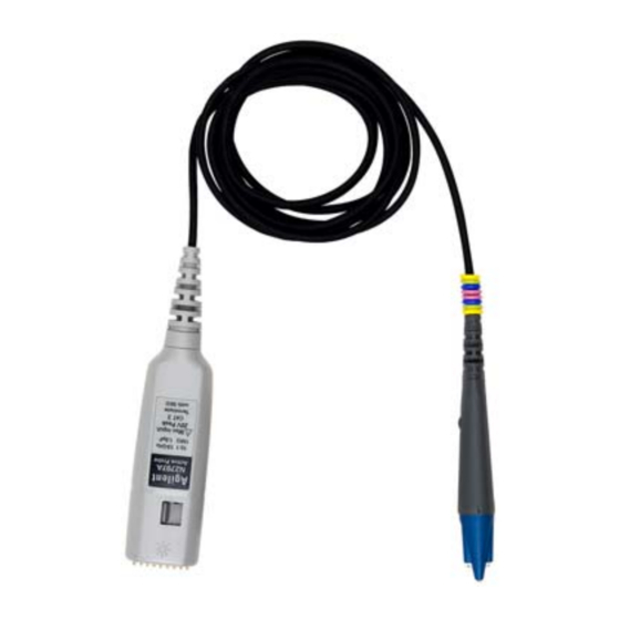
Using the Probe For high signal integrity probing, the N2797A 1.5 GHz active probe is a perfect complements to Agilent’s 500 MHz – 600 MHz and 1 GHz bandwidth scopes. The probe is powered directly by the InfiniiVision and Infiniium AutoProbe interface, eliminating the need for an additional power supply. -
Page 7: Probe Features
1. Up to four probes can be connected to the oscilloscope. The table also lists the minimum required firmware version for the oscilloscope. NOTE The N2797A probe is designed for oscilloscopes with 1 MW AutoProbe-interface channel inputs. Table 1 Compatible Oscilloscopes and Support... - Page 8 All of the supplied accessories can be used at the probe’s specified extreme temperature range of –40°C to +85°C except the (–40°F to +185°F) flex nose clip and pico hook tips. These adapters have a slightly reduced temperature range of –20°C to +80°C (–4°F to +176°F). N2797A User’s Guide...
- Page 9 Using the Probe Probe Features Figure 2 Accessories Supplied With the Probe (Not to Scale) N2797A User’s Guide...
- Page 10 “ ”. Table 4 shows additional accessories that work with the probe, but are not provided with the probe. Notice that most of these accessories can not be used at extreme temperature range of the probe. N2797A User’s Guide...
- Page 11 (10 cm), extreme temp –20°C to +85°C (–4°F to +185°F) Short Y-Lead Adapter with damping resistor 5061-7387 (5 cm), extreme temp Right Angle Ground (5 cm), extreme temp Same as probe 5061-7384 –40°C to +85°C (–40°F to +185°F) N2797A User’s Guide...
- Page 12 Right Angle Ground (5 cm) 5061-7399 Ground Lead (6 cm) 0°C to 50°C 5061-7395 (32°F to 122°F) Ground Lead (12 cm) 5061-7396 Offset Ground 0°C to 50°C 5061-7394 (32°F to 122°F) N2787A 3D Probe Positioner Not Specified — — N2797A User’s Guide...
- Page 13 Once the accessory is removed, insert the new accessory until it is seated in the contact socket. In order to insert the probe tip completely into the housing, carefully press the probe tip against a hard surface. Figure 3 Tip and Grounding Connections N2797A User’s Guide...
-
Page 14: Using The Accessory Tips And Grounds
18 1.0 GHz “Solderable Tip with Right-Angle Ground” on page 17 800 MHz “9 cm Y-Leads with 0.1” Headers” on page 18 800 MHz “Y-Lead with Flexible Nose Clips and 500 MHz Pico Hooks” on page 19 N2797A User’s Guide... - Page 15 Handle the probe with care to avoid injury, especially when it is fitted with the sharp rigid or spring tip. When inserting the tip, insert the end with the ridge into the probe head as shown in Figure Figure 4 Inserting the Rigid Tip N2797A User’s Guide...
- Page 16 0.025 inch square) diameter pins. The maximum insertion depth is 7.5 mm (0.295 inch) and the outer insulation of the socket is less than 2.54 mm. You can use it for 2.54 mm pitch (0.1 inch) terminals. Figure 5 Probe with Y-Leads Attached N2797A User’s Guide...
- Page 17 Therefore, keep the right-angle ground lead as straight as possible for maximum measurement bandwidth. Loops and bends in the ground lead, as shown in this picture, can reduce the measurement bandwidth. Figure 6 Placing the Probe Onto the Solderable Tip N2797A User’s Guide...
- Page 18 The maximum insertion depth is 7.5 mm (0.295 inch) and the outer insulation of the socket is less than 2.54 mm. You can use it for 2.54 mm pitch (0.1 inch) terminals. Figure 7 Probe with Y-Leads Attached N2797A User’s Guide...
- Page 19 CAUTION The clips have an ambient operating temperature range of –20°C to +80°C (–4°F to +176°F). This is a slightly reduced range compared to the probe. Figure 8 Probe with Flexible Nose Clips Attached N2797A User’s Guide...
-
Page 20: Dynamic Range And Offset Voltage Limitations
You could then zoom in to see the detail at a higher resolution. Trying to measure a signal out of the dynamic range may result in a clipped or distorted waveform. Figure 9 Dynamic Range and Offset Limits N2797A User’s Guide... -
Page 21: Functional Test
Connect the probe tip to the oscilloscope’s probe compensation output. Enable autoscale on the oscilloscope. A square wave should now be displayed on the oscilloscope, if the probe is functioning properly. N2797A User’s Guide... -
Page 22: Inspecting The Probe
If the shipping container is damaged, or the cushioning materials show signs of stress, notify the carrier as well as your Agilent Technologies Sales Office. Keep the shipping materials for the carrier’s inspection. The Agilent Technologies office will arrange for repair or replacement at Agilent Technologies’... -
Page 23: Returning The Probe For Service
Perform the following steps before shipping the probe back to Agilent Technologies for service. Contact your nearest Agilent sales office for information on obtaining an RMA number and return address. -
Page 24: Safety Information
Make sure to comply with the voltage versus frequency derating curve found in this manual. WARNING Keep Away From Live Circuits. Avoid open circuitry. Do not touch connections or components when power is present. N2797A User’s Guide... - Page 25 The probe cable is a sensitive part of the probe and, therefore, you should be careful not to damage it through excessive bending or pulling. Avoid any mechanical shocks to this product in order to guarantee accurate performance and protection. N2797A User’s Guide...
- Page 26 Using the Probe Safety Information N2797A User’s Guide...
-
Page 27: Probe Calibration
Infiniium and InfiniiVision oscilloscopes. For additional information on the probe calibration refer to the oscilloscope’s user documentation. CAUTION Always wear an ESD wrist strap when working with active probes. Not doing so can result in the probe becoming permanently damaged. N2797A User’s Guide... -
Page 28: Calibrating The Probe On Infiniium Oscilloscopes
If the oscilloscope needs calibration, perform a user calibration before the probe calibration. On the oscilloscope, click Utilities > Calibration. On the oscilloscope, click Setup > Probes. In the Probe Calibration dialog box, select the tab representing the channel that has the probe attached. N2797A User’s Guide... - Page 29 NEVER solder a probe tip to the thick-film gold. The gold will immediately dissolve into the solder and disappear. NOTE If you are using the browser tip, it is recommended that you use the N2787A 3D Probe Positioner to hold the probe in place. N2797A User’s Guide...
- Page 30 Calibrating the Probe on Infiniium Oscilloscopes NOTE You can check that the probe leads are correctly connected by pressing the front panel autoscale button. A stable step should be shown on the screen. Pressing autoscale will close the Probe Calibration dialog box. N2797A User’s Guide...
-
Page 31: Calibrating The Probe On Infiniivision Oscilloscopes
Demo 2 / Probe Comp terminal and the ground tip to the ground terminal. Figure 11 Probe Calibration Terminals on 3000 X-Series Oscilloscope Press the Channel on/off key to turn the channel on (if the channel is off). In the Channel Menu, press the Probe softkey. N2797A User’s Guide... - Page 32 Probe Calibration Calibrating the Probe on InfiniiVision Oscilloscopes Press the Calibrate Probe softkey and follow the instructions on the display. N2797A User’s Guide...
- Page 33 Characteristics and Specifications This chapter provides the characteristics and specifications for the N2797A active probe. The probe and oscilloscope should be warmed up for at least 20 minutes before any testing and the environmental conditions should not exceed the probe’s specified limits.
- Page 34 < 2.5 mV (referred to input) Output Impedance 50Ω Internal Power Agilent AutoProbe interface from oscilloscope (InfiniiVision and Infiniium) a Denotes warranted electrical specification at 25 °C room temperature after 20 minute warm-up. All others are typical. N2797A User’s Guide...
-
Page 35: Characteristics And Specifications Dimensions
Characteristics and Specifications Dimensions Dimensions N2797A User’s Guide... - Page 36 Characteristics and Specifications Dimensions N2797A User’s Guide...
-
Page 37: Performance Data Plots
Performance Data Plots Figure 12 shows the frequency response for the spring or rigid probe tip and an offset ground or ground blade. Figure 12 Frequency Response (Vout/Vin) N2797A User’s Guide... - Page 38 Performance Data Plots Figure 13 Input Impedance Equivalent Model Figure 14 Typical Input Impedance Plot N2797A User’s Guide...
-
Page 39: Performance Verification
Test 1. DC Input Resistance Test 2. Bandwidth Performance Test Record These procedures are used to test the warranted specifications for the N2797A. The recommended calibration test interval is once a year or as required. Use the equipment listed in Table 9 on page 40. - Page 40 Outside thread 3.5 mm (male) to 3.5 mm No Substitute Agilent 5062-1247 (female) adapter Cable (2) 3.5 mil; SMA; High Quality Agilent 8120-4948 Cable 1.5 mil Probe Power Extension No Substitute Agilent 01143-61602 PV/DS Test Board No Substitute (In E2655B Kit) Agilent E2655-66503 N2797A User’s Guide...
-
Page 41: Test 1. Dc Input Resistance
Connect the DMM probes between the probe tip and ground at the tip of the probe. Set up the DMM to measure resistance. The resistance should read 1 MW ± 3%. Record the resistance in Table 10 on page 49. N2797A User’s Guide... -
Page 42: Test 2. Bandwidth
Select the log freq screen key. Connect the probe under test to the AutoProbe Adapter and power the probe using the 1143A power supply as shown in Figure 15 on page 43. Install the outside thread adapter to the AutoProbe Adapter. N2797A User’s Guide... - Page 43 Connect the PV fixture to the Port 1 on the VNA using a high quality SMA cables. Connect the cable to the pincher side of PV fixture as shown in Figure 16 on page 44. The calibration reference plane is at the other end of PV fixture. N2797A User’s Guide...
- Page 44 Wait until the VNA beeps indicating that it has completed the task. Connect load end of Calibration Standard to the non- pincher side of the PV/DS test board. Select the loads screen key under the Forward group. N2797A User’s Guide...
- Page 45 Connect the open end of Calibration Standard to the available end of the PORT 2 SMA cable. Select the open screen key under the Reverse group. Wait until the VNA beeps indicating that it has completed the task. N2797A User’s Guide...
- Page 46 You have just calibrated the other side of the reference plane. Press standards done key. Connect the PORT 2 SMA cable to the non- pincher side of PV fixture as shown in Figure Figure 18 Forward and Reverse Setup N2797A User’s Guide...
- Page 47 Select [display] key then data->memory screen key. You have now saved Vin waveform into the VNA's memory for future use. Measuring Vout Response Disconnect the PORT 2 cable from PV/DS test board and attach to probe output on the AutoProbe Adapter. N2797A User’s Guide...
- Page 48 –3 dB below center screen. Read the marker frequency measurement and record it in Table 10 on page 49. The bandwidth test passes if the frequency measurement is greater than or equal to the probe's bandwidth limit, which is 1.5 GHz. N2797A User’s Guide...
-
Page 49: Performance Test Record
Performance Verification Performance Test Record Performance Test Record Table 10 Performance Test Record Model #: N2797A Date: Tested by: Serial #: Recommended next test date: Recommended Test Interval: 1 year / 2000 hours Probe Amplifier Test Limits Result Pass/Fail Test 1. DC Input Resistance 1 MΩ... - Page 50 Performance Verification Performance Test Record N2797A User’s Guide...
- Page 51 20, oscilloscope specifications, compatibility, spring ground, Infiniium, spring probe tip, InfiniiVision, supplied accessories, ESD, oscilloscope compatibility, output impedance, Y-lead adapter, 10, flex nose clip, 10, Y-lead with clips, functional test, performance test record, Y-leads, 16, performance verification, N2797A User’s Guide...
- Page 52 Index N2797A User’s Guide...