Sign In
Upload
Manuals
Brands
VAT Manuals
Control Unit
613 Series
VAT 613 Series Manuals
Manuals and User Guides for VAT 613 Series. We have
3
VAT 613 Series manuals available for free PDF download: Installation, Operating, & Maintenance Instructions
VAT 613 Series Installation, Operating, & Maintenance Instructions (149 pages)
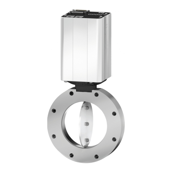
Butterfly Pressure Control Valve with RS232 interface, DN 25-320 mm, I.D. 1" - 12", 2 sensor inputs / analog outputs / ±15V SPS / PFO
Brand:
VAT
| Category:
Control Unit
| Size: 4 MB
Table of Contents
Table of Contents
3
Description of Product
6
Identification of Product
6
Firmware
6
Use of Product
6
Used Abbreviations
6
Related Documents
6
Important Information
6
Technical Data
7
Control and Actuating Unit
7
Valve Unit
7
Safety
8
Compulsory Reading Material
8
Danger Levels
8
Personnel Qualifications
9
Safety Labels
9
Design and Function
10
Design
10
Function
10
Pressure Control System Overview and Function
11
Principle of a Pressure Control System
12
Installation
13
Initial Procedure
13
Unpacking
14
Installation into the System
15
Installation Hints
16
Installation Space Condition
16
Admissible Forces
17
Admissible Forces at Controller
18
Tightening Torque Dns 40 - 50Mm
19
Tightening Torque Dns 63 - 100Mm
20
Connection Overview
21
Power-, Ground- and Sensor Connection
22
Connection Cable Recommendations
22
Ground Connection
23
Power and Sensor Supply Concepts
24
Drive Power Enabled Switch, Safety Mode
28
Power up
29
Power Down, Power Failure Option
29
Power down Behavior in Case of Power Failure
29
Power Fail Option
29
Service Port, CPA Software
30
How to Start
30
Update
31
Display Information
32
Power up
32
Operation
33
Error
33
System Settings and States
34
Identification
34
Statistics
35
Warning/Error
36
Service
36
Valve Settings and States
37
States
37
Homing
37
Cycle Counter
38
Position Restriction
38
Position Adaption
39
Interface RS232/485
40
Operation Mode RS232/ RS485
40
Rs232
40
Rs485
41
Command Set
42
Position and Pressure Units
46
Compound Commands
47
Parameter Overview
50
Compatible Command Sets
60
Digital IO on the RS Interface Connector
75
Pressure Sensor
78
Mechanical Connection Requirements
78
Configuration
79
Crossover (2 Sensor Operation Mode)
81
Zero Adjust
82
Logarithmic Pressure
83
Power Connector Digital IO
84
Digital Input
84
Digital Output
85
Operation
86
Access Mode
87
Overview
87
Remote and Locked Operation
87
Local Operation
87
Control Mode
88
View
89
Pressure Control
90
Controller Units
90
Control Algorithm
91
Adaptive Algorithm
93
PI Algorithm
104
Pressure Ramp
110
Profile Ramp
113
Automated Controller Selector
116
Control Position Restriction
117
Store Control Parameter Volatile
117
Position Control
118
Parameter
118
Position Ramp
118
Operation under Increased Temperature
119
Trouble Shooting
120
Warnings
120
Errors
122
Error Recovery
122
Error Bitmap
122
Error Number
123
Error Code
123
Troubleshooting List
125
Maintenance
126
Maintenance Intervals
126
Maintenance Procedures
127
Replacement of Shaft Feedthrough Seals and Valve Cleaning
128
Replacement of Option Board
132
Repairs
137
FPR Service
137
Dismounting and Storage
138
Dismounting
138
Storage
139
Packaging and Transport
140
Packaging
141
Transport
141
Disposal
142
Spare Parts
143
ISO-KF for DN 25 - 50 MM
144
Drawing ISO-KF
144
ISO-KF Valve Unit - Aluminum Blank, Without Heating
145
ISO-KF Valve Unit - Stainless Steel, Without Heating
145
Seals and Grease
145
ISO-F for DN 63 - 320 MM
146
Drawing ISO-F
146
ISO-F Valve Unit - Aluminum Blank, Without Heating
147
ISO-F Valve Unit - Stainless Steel, Without Heating
147
Seals and Grease
147
Control Unit and Accessories
148
Control and Actuating Unit
148
Accessories
148
Centering Ring with VITON ® O-Ring
148
Advertisement
VAT 613 Series Installation, Operating, & Maintenance Instructions (129 pages)
Butterfly Pressure Control Valve with Profibus interface VAT2 profile, DN 25-320 mm, I.D. 1“ - 12", 2 sensor inputs / analog outputs / +-15V SPS / PFO
Brand:
VAT
| Category:
Control Unit
| Size: 4 MB
Table of Contents
Table of Contents
3
Description of Product
6
Identification of Product
6
Firmware
6
Use of Product
6
Used Abbreviations
6
Related Documents
6
Important Information
6
Technical Data
7
Control and Actuating Unit
7
Valve Unit
7
Safety
8
Compulsory Reading Material
8
Danger Levels
8
Personnel Qualifications
9
Safety Labels
9
Design and Function
10
Design
10
Function
10
Pressure Control System Overview and Function
11
Principle of a Pressure Control System
12
Installation
13
Initial Procedure
13
Unpacking
14
Installation into the System
15
Installation Hints
16
Installation Space Condition
16
Admissible Forces
17
Admissible Forces at Controller
18
Tightening Torque Dns 40 - 50Mm
19
Tightening Torque Dns 63 - 100Mm
20
Connection Overview
21
Power-, Ground- and Sensor Connection
22
Connection Cable Recommendations
22
Ground Connection
23
Power and Sensor Supply Concepts
24
Drive Power Enabled Switch, Safety Mode
28
Power up
29
Power Down, Power Failure Option
29
Power down Behavior in Case of Power Failure
29
Power Fail Option
29
Service Port, CPA Software
30
How to Start
30
Update
31
Display Information
32
Power up
32
Operation
33
Error
33
System Settings and States
34
Identification
34
Statistics
35
Warning/Error
36
Service
36
Valve Settings and States
37
States
37
Homing
37
Cycle Counter
38
Position Restriction
38
Position Adaption
39
Interface Profibus
40
Connection
40
Leds
42
Configuration
43
GSD File
44
Status
44
Connection Loss Reaction
46
Cyclic Data Setting
46
Cyclic Buffers
47
Troubleshooting
57
Pressure Sensor
58
Mechanical Connection Requirements
58
Configuration
59
Crossover (2 Sensor Operation Mode)
61
Zero Adjust
62
Logarithmic Pressure
63
Power Connector Digital IO
64
Digital Input
64
Digital Output
65
Operation
66
Access Mode
67
Overview
67
Remote and Locked Operation
67
Local Operation
67
Control Mode
68
View
69
Pressure Control
70
Controller Units
70
Control Algorithm
71
Adaptive Algorithm
73
PI Algorithm
84
Pressure Ramp
90
Profile Ramp
93
Automated Controller Selector
96
Control Position Restriction
97
Store Control Parameter Volatile
97
Position Control
98
Parameter
98
Position Ramp
98
Operation under Increased Temperature
99
Trouble Shooting
100
Warnings
100
Errors
102
Error Recovery
102
Error Bitmap
102
Error Number
103
Error Code
103
Troubleshooting List
105
Maintenance
106
Maintenance Intervals
106
Maintenance Procedures
107
Replacement of Shaft Feedthrough Seals and Valve Cleaning
108
Replacement of Option Board
111
Repairs
116
FPR Service
116
Dismounting and Storage
117
Dismounting
117
Storage
118
Packaging and Transport
119
Packaging
120
Transport
120
Disposal
121
Spare Parts
122
ISO-KF for DN 25 - 50 MM
123
Drawing ISO-KF
123
ISO-KF Valve Unit - Aluminum Blank, Without Heating
124
ISO-KF Valve Unit - Stainless Steel, Without Heating
124
Seals and Grease
124
ISO-F for DN 63 - 320 MM
125
Drawing ISO-F
125
ISO-F Valve Unit - Aluminum Blank, Without Heating
126
ISO-F Valve Unit - Stainless Steel, Without Heating
126
Seals and Grease
127
Control Unit and Accessories
127
Control and Actuating Unit
127
Accessories
127
Centering Ring with VITON ® O-Ring
128
VAT 613 Series Installation, Operating, & Maintenance Instructions (109 pages)
Butterfly Pressure Control Valve
Brand:
VAT
| Category:
Control Unit
| Size: 2 MB
Table of Contents
Table of Contents
3
Description of Product
6
Identification of Product
6
Use of Product
6
Used Abbreviations
6
Related Documents
6
Important Information
6
Technical Data
7
Control and Actuating Unit
7
Devicenet
8
Valve Unit
9
Safety
10
Compulsory Reading Material
10
Danger Levels
10
Personnel Qualifications
11
Safety Labels
11
Design and Function
12
Design
12
Function
12
Pressure Control System Overview and Function
13
Principle of a Pressure Control System
14
Installation
15
Unpacking
15
Installation into the System
16
Installation Space Condition
17
Connection Overview
17
Installation Procedure
18
Tightening Torque
20
Mounting of CF-F Flanges
20
Admissible Forces
20
Admissible Forces at Controller
21
Heated Condition
22
Requirements to Sensor Connection
22
Electrical Connection
23
Ground Connection
24
Power and Sensor Supply Concepts
25
Digital Input/Output and Analog Output Connections
31
Devicenet® Interface Connection
33
Service Port Connection
33
Initial Operation
34
Valve Configuration
35
Homing Start Option
35
Power Failure Option
36
Digital I/O
36
Devicenet Interface Configuration
37
Interface® Configuration (Devicenet®)
37
Sensor Configuration
39
Sensor Crossover (2 Sensor Operation Mode)
40
Zero Adjust
41
Learn (Adaptive Control Algorithm)
42
Pressure Control
45
Pressure Control Operation with 2 Sensors
46
Control Parameters
47
Choose Correct Control Algorithm
51
Tuning of Control Performance
52
Devicenet Interface Commands
62
Assembly Objects
62
Assembly Object Bit Map
63
Explicit Messaging Control Commands
65
Explicit Messaging Inquiry Commands
67
Explicit Messaging Setup Commands
73
Operation
78
Normal Operation
78
Remote Operation
78
Local Operation
79
Close Valve
80
Open Valve
80
Position Control
80
Pressure Control
80
Display Information
81
Power up
81
Operation
82
Error
82
Safety Mode
82
Operation During Power up
83
Behavior in Case of Power Failure
83
Operation under Increased Temperature
83
Trouble Shooting
84
General
84
Errors
87
6.2.1 Controller Display
87
6.2.2 Error Numbers
87
Error Code
87
Maintenance
89
Maintenance Intervals
89
Maintenance Procedures
90
Replacement of Shaft Feedthrough Seals and Valve Cleaning
91
Replacement of Option Board
94
Repairs
98
Dismounting and Storage
99
Dismounting
99
Storage
100
Packaging and Transport
101
Packaging
102
Transport
102
Disposal
103
Spare Parts
104
Drawing
105
Sample Picture
105
ISO-KF Valve Unit - Aluminum Blank, Without Heating
106
ISO-KF Valve Unit - Stainless Steel, Without Heating
106
Seals and Grease
106
Control and Actuating Unit
107
Accessories
107
Appendix
108
Advertisement
Advertisement
Related Products
VAT 613-GH Series
VAT 613-AH Series
VAT 613-HH Series
VAT 613-CH Series
VAT 613-GF Series
VAT 613-AF Series
VAT 613-HF Series
VAT 613-CF Series
VAT 613 GQ Series
VAT 613 AQ Series
VAT Categories
Control Unit
Controller
Refrigerator
Camcorder
Keypad
More VAT Manuals
Login
Sign In
OR
Sign in with Facebook
Sign in with Google
Upload manual
Upload from disk
Upload from URL