Advertisement
Quick Links
Operating instructions
Video control device
1288 ..
Gira
Giersiepen GmbH & Co. KG
Elektro-Installations-
Systeme
Industriegebiet Mermbach
Dahlienstrasse
42477 Radevormwald
P.O. Box 12 20
42461 Radevormwald
Germany
Tel
+49 (0)21 95 - 602-0
Fax +49 (0)21 95 - 602-191
www.gira.de
info@gira.de
1
Safety information
Electrical devices may only be
installed and connected by a qua-
lified electrician.
Serious injury, fire or damage to property
possible. Read and observe these instruc-
tions completely.
These instructions are an integral compo-
nent of the product and must remain with
the end customer.
Intended use
- Provision of bus voltage (26 V DC ± 2 V)
for the door communication system
- Control of up to 15 colour cameras (5 vid-
eo door stations and 10 DCS camera
gateways),
- Power supply of
- up to 31 video devices (e.g. 28 home
stations, 2 door stations with colour
camera, 1 DCS switching actuator)
- up to 70 audio devices
- up to 2 colour cameras (more with ad-
ditional power supply)
- Call-button illumination (max. 15, the
number of call-button illuminations that
can be supplied with power depends on
the system size and the number of
home stations operated in parallel)
- Provision of the door opener control incl.
power supply (12 V AC, 1,1 A) for the door
opener.
- Activation of the entire door communica-
tion bus system's programming mode.
- Electronic overload, short-circuit and
overtemperature protection.
- "Operation" LED indicator (mains volt-
age), overload/short circuit,
- Adjustable door opener activation time.
Assembly
For drip and splash-proof installation,
mount the control device on a top-hat rail in
the distributor.
The mains and bus connection is made
using screw terminals.
The mains connection must be made using
an all-pole mains switch with a contact
opening of at least 3 mm.
The functional earth must be connected
using a distributor block.
The control device's ventilation slits must
not be obstructed.
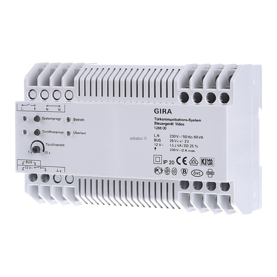
Electrical connections (Fig. 1)
L, N
Mains connection terminals L and N (AC
230 V, 50 Hz).
(Functional earth)
A functional earth is connected to this ter-
minal for functional reasons.
Connect the earth potential to the earth ter-
minal with a suitable line (not a green/yel-
low line).
Bus
Power supply output of the Gira door com-
munication bus with a regulated DC voltage
(26 V DC ± 2 V, 700 mA).
(Door opener output 230 V~/max. 2 A)
A door opener that cannot be connected to
the "12 V~" terminals due to its electrical
values (e.g. very low-ohm or 24 V) can be
connected to the equipotential-bonding
relay contact with an external power supply
(230 V~, max. 2 A).
L1
N
Remove blank plug
Before connection, remove the blank plug
from the terminal
.
12 V~ (door opener output 12 V~)
The 12 V~ output is used to supply power to
and control the door opener (8–12 V, max.
1.1 A).
Functional earth
No permanent 12 V output
Power is not continuously supplied at the
door opener output. The 12 V supply at the
door opener output is only active for the
door opener time specified on the setting
controller.
Advertisement

Related Manuals for Gira 1288 Series


Summary of Contents for Gira 1288 Series
- Page 1 - up to 70 audio devices - up to 2 colour cameras (more with ad- ditional power supply) Power supply output of the Gira door com- - Call-button illumination (max. 15, the munication bus with a regulated DC voltage number of call-button illuminations that (26 V DC ±...
- Page 2 Press “System progr.” button (3 s), the problem to your supplier (retailer/instal- “System progr.” LED flashes. lation company/electronics retailer). Press “Door-opener progr.” button (3 s), “Door-opener progr.” LED flashes. They will forward the devices to the Gira Service Centre. Systemprogr. Betrieb Door station Türöffnerprogr.
Need help?
Do you have a question about the 1288 Series and is the answer not in the manual?
Questions and answers