Table of Contents
Advertisement
Quick Links
www.ti.com
User's Guide
TPSF12C3QEVM Active EMI Filter Evaluation Module for
Three-Phase AC Power Systems
The TPSF12C3QEVM evaluation module (EVM) is specifically designed to conveniently evaluate the
performance of the TPSF12C3-Q1
total size of the common-mode (CM) electromagnetic interference (EMI) filter in three-phase AC power systems,
either with or without a neutral connection.
The TPSF12C3-Q1 provides a very low impedance path for CM noise in the frequency range of interest for EMI
measurement and helps to meet prescribed limits for international EMI standards, such as:
•
CISPR 11, EN 55011 – Industrial, Scientific and Medical (ISM) applications
•
CISPR 25, EN 55025 – Automotive applications
•
CISPR 32, EN 55032 – Multimedia applications
•
MIL-STD-461 – Military and defense applications
•
RTCA DO-160 – Airborne applications
Enabling up to 25 dB of CM noise reduction at the lower end of specified frequency ranges (for example,
150 kHz to 3 MHz) significantly reduces the size, cost and weight of the common-mode filter implementation,
specifically the common-mode chokes. The device senses the high-frequency noise on each power line using
a set of sense capacitors and injects noise-canceling currents back into the power lines using an injection
capacitor.
A header on the EVM provides connections to the sense and inject capacitors, which are high-voltage rated
components located off-board at or near the passive filter solution. Also included on the EVM are connections for
the bias power supply (VDD and GND), which is set between 8 V and 16 V, and a remote enable (EN) signal.
The GND terminal of the EVM refers to the chassis or Earth ground of the system.
The damping and compensation component values included with this EVM can require modification,
depending on the specifics of the EMI filter implementation and the target application. Refer to the
TPSF12C3-Q1 Standalone Active EMI Filter for Common-mode Noise Mitigation in Three-Phase
AC Automotive Power Systems
guidance pertaining to AEF circuit operation, passive component selection and expected EMI
performance.
SLVUCM2 – JANUARY 2023
Submit Document Feedback
ABSTRACT
power-supply active filter
Note
data sheet and
TPSF12C3-Q1 quickstart calculator
TPSF12C3QEVM Active EMI Filter Evaluation Module for Three-Phase AC
Copyright © 2023 Texas Instruments Incorporated
IC. The solution helps to substantially reduce the
for additional
1
Power Systems
Advertisement
Table of Contents

Related Manuals for Texas Instruments TPSF12C3QEVM


Summary of Contents for Texas Instruments TPSF12C3QEVM
- Page 1 User’s Guide TPSF12C3QEVM Active EMI Filter Evaluation Module for Three-Phase AC Power Systems ABSTRACT The TPSF12C3QEVM evaluation module (EVM) is specifically designed to conveniently evaluate the performance of the TPSF12C3-Q1 power-supply active filter IC. The solution helps to substantially reduce the total size of the common-mode (CM) electromagnetic interference (EMI) filter in three-phase AC power systems, either with or without a neutral connection.
-
Page 2: Table Of Contents
HotRod ™ is a trademark of Texas Instruments. All trademarks are the property of their respective owners. TPSF12C3QEVM Active EMI Filter Evaluation Module for Three-Phase AC SLVUCM2 – JANUARY 2023 Power Systems Submit Document Feedback Copyright © 2023 Texas Instruments Incorporated... -
Page 3: High-Density Evm Description
1" × 0.8" (25.4 mm × 20.3 mm) • The EVM includes a right-angle header for easy hookup to an EMI filter board SLVUCM2 – JANUARY 2023 TPSF12C3QEVM Active EMI Filter Evaluation Module for Three-Phase AC Submit Document Feedback Power Systems Copyright © 2023 Texas Instruments Incorporated... -
Page 4: Evm Performance Specifications
This performance metric can change based on the operating supply voltage, ambient temerature, passive filter component values, compensation and damping component values, and other parameters. TPSF12C3QEVM Active EMI Filter Evaluation Module for Three-Phase AC SLVUCM2 – JANUARY 2023 Power Systems Submit Document Feedback Copyright ©... -
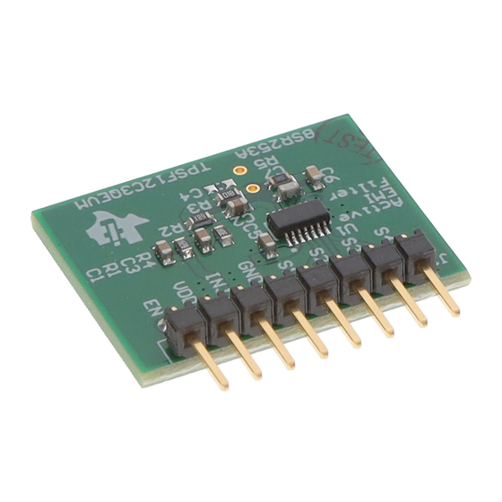
Page 5: Evm Photo
GND is tied to Earth or chassis ground of the system. Figure 3-1. TPSF12C3QEVM Photo CAUTION Caution Hot surface. Contact may cause burns. Do not touch. SLVUCM2 – JANUARY 2023 TPSF12C3QEVM Active EMI Filter Evaluation Module for Three-Phase AC Submit Document Feedback Power Systems Copyright © 2023 Texas Instruments Incorporated... -
Page 6: Evm Setup, Connections And Validation
Earth ground before power is applied to the EVM. Pin positions of header J1 designate left to right when viewed from the top side of the EVM. TPSF12C3QEVM Active EMI Filter Evaluation Module for Three-Phase AC SLVUCM2 – JANUARY 2023... -
Page 7: Evm Connections
. The connections are similar for a three-wire system where the neutral is unavailable, except S4 is tied to GND as shown in Figure 4-2. SLVUCM2 – JANUARY 2023 TPSF12C3QEVM Active EMI Filter Evaluation Module for Three-Phase AC Submit Document Feedback Power Systems Copyright © 2023 Texas Instruments Incorporated... -
Page 8: Evm Performance Validation
Three-Phase AC Automotive Power Systems data sheet and TPSF12C3-Q1 quickstart calculator additional context pertaining to EVM component selection and optimization. TPSF12C3QEVM Active EMI Filter Evaluation Module for Three-Phase AC SLVUCM2 – JANUARY 2023 Power Systems Submit Document Feedback Copyright © 2023 Texas Instruments Incorporated... -
Page 9: Test Data And Performance Curves
1 s/DIV Figure 5-3. IEC 61000-4-5 Negative Surge, 5-kV Single Strike – 1 µs/div (a), 200 µs/div (b) SLVUCM2 – JANUARY 2023 TPSF12C3QEVM Active EMI Filter Evaluation Module for Three-Phase AC Submit Document Feedback Power Systems Copyright © 2023 Texas Instruments Incorporated... -
Page 10: Figure 5-4. Iec 61000-4-5 Surge, 5-Kv Repetitive Strike At 10-Second Intervals - Positive (A), Negative (B)
10 s/DIV 10 A/DIV 10 s/DIV Figure 5-4. IEC 61000-4-5 Surge, 5-kV Repetitive Strike at 10-Second Intervals – Positive (a), Negative (b) TPSF12C3QEVM Active EMI Filter Evaluation Module for Three-Phase AC SLVUCM2 – JANUARY 2023 Power Systems Submit Document Feedback... -
Page 11: Evm Documentation
COMP1 COMP1 IGND 10pF COMP2 REFGND 10nF TPSF12C3QDYYRQ1 IGND IGND COMP2 1.50k Figure 6-1. EVM Schematic SLVUCM2 – JANUARY 2023 TPSF12C3QEVM Active EMI Filter Evaluation Module for Three-Phase AC Submit Document Feedback Power Systems Copyright © 2023 Texas Instruments Incorporated... -
Page 12: Bill Of Materials
Disc DE2B3SA681KN3AX02F MuRata SEN4 4.7 nF CAP, CERM, 4.7 nF, 300 VAC, Y2 Disc DE2E3SA472MA3BX02F MuRata TPSF12C3QEVM Active EMI Filter Evaluation Module for Three-Phase AC Power Systems SLVUCM2 – JANUARY 2023 Submit Document Feedback Copyright © 2023 Texas Instruments Incorporated... -
Page 13: Pcb Layout
The PCB is 62-mils standard thickness with 1-oz copper on all layers. Figure 6-2. 3D Top View Figure 6-3. 3D Bottom View SLVUCM2 – JANUARY 2023 TPSF12C3QEVM Active EMI Filter Evaluation Module for Three-Phase AC Submit Document Feedback Power Systems Copyright © 2023 Texas Instruments Incorporated... -
Page 14: Figure 6-4. Top Layer Copper
EVM Documentation www.ti.com Figure 6-4. Top Layer Copper Figure 6-5. Layer 2 Copper TPSF12C3QEVM Active EMI Filter Evaluation Module for Three-Phase AC SLVUCM2 – JANUARY 2023 Power Systems Submit Document Feedback Copyright © 2023 Texas Instruments Incorporated... -
Page 15: Figure 6-6. Layer
EVM Documentation Figure 6-6. Layer 3 Copper Figure 6-7. Bottom Layer Copper (Viewed From Top) SLVUCM2 – JANUARY 2023 TPSF12C3QEVM Active EMI Filter Evaluation Module for Three-Phase AC Submit Document Feedback Power Systems Copyright © 2023 Texas Instruments Incorporated... -
Page 16: Assembly Drawings
6.4 Assembly Drawings Figure 6-8. Top Assembly (Top View) Figure 6-9. Bottom Assembly (Bottom View) TPSF12C3QEVM Active EMI Filter Evaluation Module for Three-Phase AC SLVUCM2 – JANUARY 2023 Power Systems Submit Document Feedback Copyright © 2023 Texas Instruments Incorporated... -
Page 17: Multi-Layer Stackup
EVM Documentation 6.5 Multi-Layer Stackup Figure 6-10. Layer Stackup SLVUCM2 – JANUARY 2023 TPSF12C3QEVM Active EMI Filter Evaluation Module for Three-Phase AC Submit Document Feedback Power Systems Copyright © 2023 Texas Instruments Incorporated... -
Page 18: Device And Documentation Support
AN-2162 Simple Success With Conducted EMI From DC/DC Converters Application Report application report • Texas Instruments, Simplify Low EMI Design with Power Modules white paper TPSF12C3QEVM Active EMI Filter Evaluation Module for Three-Phase AC SLVUCM2 – JANUARY 2023 Power Systems Submit Document Feedback Copyright © 2023 Texas Instruments Incorporated... - Page 19 STANDARD TERMS FOR EVALUATION MODULES Delivery: TI delivers TI evaluation boards, kits, or modules, including any accompanying demonstration software, components, and/or documentation which may be provided together or separately (collectively, an “EVM” or “EVMs”) to the User (“User”) in accordance with the terms set forth herein.
- Page 20 www.ti.com Regulatory Notices: 3.1 United States 3.1.1 Notice applicable to EVMs not FCC-Approved: FCC NOTICE: This kit is designed to allow product developers to evaluate electronic components, circuitry, or software associated with the kit to determine whether to incorporate such items in a finished product and software developers to write software applications for use with the end product.
- Page 21 www.ti.com Concernant les EVMs avec antennes détachables Conformément à la réglementation d'Industrie Canada, le présent émetteur radio peut fonctionner avec une antenne d'un type et d'un gain maximal (ou inférieur) approuvé pour l'émetteur par Industrie Canada. Dans le but de réduire les risques de brouillage radioélectrique à...
- Page 22 www.ti.com EVM Use Restrictions and Warnings: 4.1 EVMS ARE NOT FOR USE IN FUNCTIONAL SAFETY AND/OR SAFETY CRITICAL EVALUATIONS, INCLUDING BUT NOT LIMITED TO EVALUATIONS OF LIFE SUPPORT APPLICATIONS. 4.2 User must read and apply the user guide and other available documentation provided by TI regarding the EVM prior to handling or using the EVM, including without limitation any warning or restriction notices.
- Page 23 Notwithstanding the foregoing, any judgment may be enforced in any United States or foreign court, and TI may seek injunctive relief in any United States or foreign court. Mailing Address: Texas Instruments, Post Office Box 655303, Dallas, Texas 75265 Copyright © 2023, Texas Instruments Incorporated...
- Page 24 TI products. TI’s provision of these resources does not expand or otherwise alter TI’s applicable warranties or warranty disclaimers for TI products. TI objects to and rejects any additional or different terms you may have proposed. IMPORTANT NOTICE Mailing Address: Texas Instruments, Post Office Box 655303, Dallas, Texas 75265 Copyright © 2023, Texas Instruments Incorporated...
Need help?
Do you have a question about the TPSF12C3QEVM and is the answer not in the manual?
Questions and answers