Advertisement
www.ti.com
EVM User's Guide: TPS3710XEVM
TPS3710X Evaluation Module
Description
The TPS3710XEVM is an evaluation module (EVM)
for the TPS37100-Q1 family of voltage supervisors.
The purpose of the this EVM is to provide a sample
design and test point for all input and output pins of
the TPS37100-Q1 and TPS37102-Q1 device to test
the functionality of TPS3700-Q1 and TPS37102-Q1.
SNVU886 – SEPTEMBER 2024
Submit Document Feedback
Features
•
Integrated buffer for supply voltage monitoring
– AOUT pin outputs a scaled down voltage of
•
Directly monitor high voltage power rails
– Wide input voltage range: 3V to 105V
•
Fast UV/OV protection in 24V/48 V systems
– Output reset latching for overvoltage fault
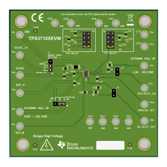
TPS3710XEVM Board
Copyright © 2024 Texas Instruments Incorporated
SENSE
TPS3710X Evaluation Module
Description
1
Advertisement
Table of Contents

Related Manuals for Texas Instruments TPS3710X


Summary of Contents for Texas Instruments TPS3710X
- Page 1 – Wide input voltage range: 3V to 105V the functionality of TPS3700-Q1 and TPS37102-Q1. • Fast UV/OV protection in 24V/48 V systems – Output reset latching for overvoltage fault TPS3710XEVM Board SNVU886 – SEPTEMBER 2024 TPS3710X Evaluation Module Submit Document Feedback Copyright © 2024 Texas Instruments Incorporated...
-
Page 2: Kit Contents
°C 1.4 Device Information The TPS3710XEVM is shipped pre-installed with the TPS37100Z91DDYYRQ1 device, but can be used with any TPS37100-Q1 and TPS37102-Q1 variant. The TPS3710X-Q1 family has analag out functionality. TPS3710X Evaluation Module SNVU886 – SEPTEMBER 2024 Submit Document Feedback... - Page 3 Evaluation Module Overview General Texas Instruments High Voltage Evaluation (TI HV EVM) User Safety Guidelines WARNING Always follow TI's set-up and application instructions, including use of all interface components within the recommended electrical rated voltage and power limits. Always use electrical safety precautions to help ensure your personal safety and those working around you.
- Page 4 Test point TP5 connects to OUT A. Test point TP6 connects J6 to CTS pin. OUT B Test point TP7 connects to OUT B. TPS3710X Evaluation Module SNVU886 – SEPTEMBER 2024 Submit Document Feedback Copyright © 2024 Texas Instruments Incorporated...
- Page 5 (Refer to Table 2-1 for configuration options). 2.2.3 OUT A and OUT B The TPS3710X-Q1 family has two reset output pin; OUT A and OUT B connected through TP5 and TP7 on the board. SNVU886 – SEPTEMBER 2024 TPS3710X Evaluation Module Submit Document Feedback Copyright ©...
- Page 6 2.2.7 CTR & CTS Time Delays The TPS3710X-Q1 family of devices contain an adjustable reset time delay pin (CTR) that controls the time with which both the OUT A pin and OUT B pin de-asserts after reaching the valid condition. The user can adjust the configuration of this pin via the jumper located at J5.
- Page 7 Table 2-4. Delay Options Capacitor Values Calculated Delay CTS & CTR = 33nF 119ms CTS & CTR = 100nF 360ms CTS & CTR = 1uF 3.6s SNVU886 – SEPTEMBER 2024 TPS3710X Evaluation Module Submit Document Feedback Copyright © 2024 Texas Instruments Incorporated...
- Page 8 3.1 EVM Performance Results The following measurements are taken using the default TPS3710XEVM with the TPS37100Z91DYYRQ1 device. Figure 3-1. Sense Delay when CTS = OPEN TPS3710X Evaluation Module SNVU886 – SEPTEMBER 2024 Submit Document Feedback Copyright © 2024 Texas Instruments Incorporated...
- Page 9 Implementation Results Figure 3-2. Reset Delay when CTR= 1 uF SNVU886 – SEPTEMBER 2024 TPS3710X Evaluation Module Submit Document Feedback Copyright © 2024 Texas Instruments Incorporated...
- Page 10 Hardware Design Files www.ti.com 4 Hardware Design Files 4.1 Schematics Figure 4-1. TPS376XEVM Schematic TPS3710X Evaluation Module SNVU886 – SEPTEMBER 2024 Submit Document Feedback Copyright © 2024 Texas Instruments Incorporated...
-
Page 11: Pcb Layout
Figure 4-3. Component Placement - Bottom Figure 4-2. Component Placement - Top Assembly Assembly Figure 4-5. Layout - Bottom Figure 4-4. Layout - Top SNVU886 – SEPTEMBER 2024 TPS3710X Evaluation Module Submit Document Feedback Copyright © 2024 Texas Instruments Incorporated... - Page 12 Hardware Design Files www.ti.com Figure 4-7. Bottom Layer Figure 4-6. Top Layer Figure 4-8. Top Solder Mask TPS3710X Evaluation Module SNVU886 – SEPTEMBER 2024 Submit Document Feedback Copyright © 2024 Texas Instruments Incorporated...
- Page 13 Keystone Electronics Wide VIN 105V 105V Window (OV & UV) Supervisor with Integrated Buffer SOT023-14 TPS37100Z91DDYYRQ1 Texas Instruments for Supply Voltage Measurements for Automotive SNVU886 – SEPTEMBER 2024 TPS3710X Evaluation Module Submit Document Feedback Copyright © 2024 Texas Instruments Incorporated...
-
Page 14: Revision History
6 Revision History NOTE: Page numbers for previous revisions may differ from page numbers in the current version. DATE REVISION NOTES September 2024 Initial Release TPS3710X Evaluation Module SNVU886 – SEPTEMBER 2024 Submit Document Feedback Copyright © 2024 Texas Instruments Incorporated... - Page 15 STANDARD TERMS FOR EVALUATION MODULES Delivery: TI delivers TI evaluation boards, kits, or modules, including any accompanying demonstration software, components, and/or documentation which may be provided together or separately (collectively, an “EVM” or “EVMs”) to the User (“User”) in accordance with the terms set forth herein.
- Page 16 www.ti.com Regulatory Notices: 3.1 United States 3.1.1 Notice applicable to EVMs not FCC-Approved: FCC NOTICE: This kit is designed to allow product developers to evaluate electronic components, circuitry, or software associated with the kit to determine whether to incorporate such items in a finished product and software developers to write software applications for use with the end product.
- Page 17 www.ti.com Concernant les EVMs avec antennes détachables Conformément à la réglementation d'Industrie Canada, le présent émetteur radio peut fonctionner avec une antenne d'un type et d'un gain maximal (ou inférieur) approuvé pour l'émetteur par Industrie Canada. Dans le but de réduire les risques de brouillage radioélectrique à...
- Page 18 www.ti.com EVM Use Restrictions and Warnings: 4.1 EVMS ARE NOT FOR USE IN FUNCTIONAL SAFETY AND/OR SAFETY CRITICAL EVALUATIONS, INCLUDING BUT NOT LIMITED TO EVALUATIONS OF LIFE SUPPORT APPLICATIONS. 4.2 User must read and apply the user guide and other available documentation provided by TI regarding the EVM prior to handling or using the EVM, including without limitation any warning or restriction notices.
- Page 19 Notwithstanding the foregoing, any judgment may be enforced in any United States or foreign court, and TI may seek injunctive relief in any United States or foreign court. Mailing Address: Texas Instruments, Post Office Box 655303, Dallas, Texas 75265 Copyright © 2023, Texas Instruments Incorporated...
-
Page 20: Important Notice
TI products. TI’s provision of these resources does not expand or otherwise alter TI’s applicable warranties or warranty disclaimers for TI products. TI objects to and rejects any additional or different terms you may have proposed. IMPORTANT NOTICE Mailing Address: Texas Instruments, Post Office Box 655303, Dallas, Texas 75265 Copyright © 2024, Texas Instruments Incorporated...
Need help?
Do you have a question about the TPS3710X and is the answer not in the manual?
Questions and answers