Advertisement
www.ti.com
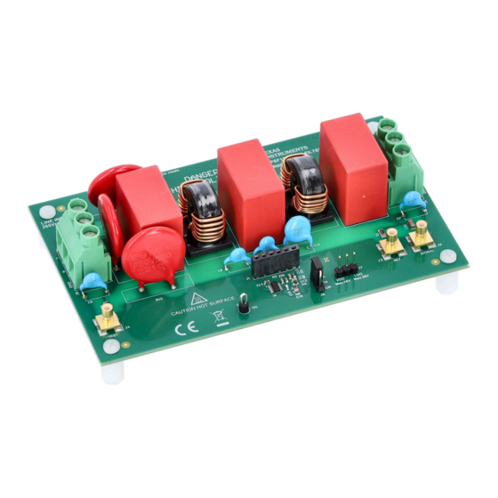
EVM User's Guide: TPSF12C1EVM-FILTER
Active EMI Filter Evaluation Module for Single-Phase AC
Power Systems
Description
The
TPSF12C1EVM-FILTER
(EVM) is specifically designed to validate the
performance of the
TPSF12C1
IC. The active EMI filter (AEF) helps to improve
the common-mode (CM) electromagnetic interference
(EMI) signature in single-phase AC power systems by
amplification of the effective Y-capacitance value.
Get Started
1. Order the
TPSF12C1EVM-FILTER
2. Study this EVM user's guide and PCB
3. Use the TPSF12C1
quickstart calculator
with EMI filter design and component selection
4. Prior to connecting the power stage, test the
active filter circuit with a low-voltage signal source
5. Connect the filter to an AC-input power stage and
verify the INJ voltage swing is within limits
6. Measure the total (DM and CM) EMI signature
and use a splitter to isolate the CM contribution
Features
•
Improved CM
EMI performance
with single-phase AC input
– Voltage-sense, current-inject AEF topology
presents low shunt impedance by amplifying
the effective value of Y-capacitance
•
Up to 30 dB reduction in the CM EMI
signature from 100 kHz to 3 MHz
SLVUCQ2 – JULY 2023
Submit Document Feedback
evaluation module
power-supply filter
EVM
layout
files
to assist
for applications
Copyright © 2023 Texas Instruments Incorporated
– A higher effective Y-capacitance enables a
reduction in CM choke size, weight and cost
•
Simple configuration for single-phase AC systems
– Integrated sensing filter and summing network
– Low Y-capacitor line-frequency leakage current
to chassis ground maintains safety
– Simplified compensation network
•
Inherent protection features for reliable design
– Withstands 6-kV+ surge with minimal external
component count
•
Helps meet IEC 61000-4-5 surge immunity
system-level specification
•
Integrated SENSE input surge protection
– Wide VDD supply voltage range of 8 V to 16 V
•
Undervoltage lockout (UVLO) set to turn on
and off at 7.7 V and 6.7 V, respectively
•
The EVM includes a high-PSRR LDO for
step-down regulation to 12 V (if needed)
– 175°C thermal shutdown protection
– Integrated VDD-to-EN pullup allows use of an
open-drain/collector device for disable function
•
Fully assembled, tested and proven two-layer
design
with 5" × 3" (127 mm × 76 mm) total area
Applications
•
On-board charger
for BEVs and PHEVs
•
Power delivery
– high-density
•
Welders and other industrial systems
•
Telecom AC/DC rectifiers
Active EMI Filter Evaluation Module for Single-Phase AC Power Systems
Description
PCB
server rack PSUs
1
Advertisement
Table of Contents

Subscribe to Our Youtube Channel
Related Manuals for Texas Instruments TPSF12C1


Summary of Contents for Texas Instruments TPSF12C1
- Page 1 • Up to 30 dB reduction in the CM EMI signature from 100 kHz to 3 MHz SLVUCQ2 – JULY 2023 Active EMI Filter Evaluation Module for Single-Phase AC Power Systems Submit Document Feedback Copyright © 2023 Texas Instruments Incorporated...
-
Page 2: Specifications
Verify that the INJ pin voltage swing is between the prescribed limits to avoid saturation and clipping. The expected EMI reduction with this EVM is up to 30 dB (with the TPSF12C1 enabled vs. disabled) when swept from 100 kHz to 3 MHz. -
Page 3: Device Information
The EVM, a practical filter circuit realization for a single-phase power system, showcases the EMI performance improvement or size reduction achievable with the TPSF12C1, a single-phase power-supply filter IC. The circuit advantages summarize as: 1. Simple filter structure – with wide operating frequency range and high stability margins 2. - Page 4 Evaluation Module Overview www.ti.com General Texas Instruments High Voltage Evaluation (TI HV EVM) User Safety Guidelines WARNING Always follow TI's set-up and application instructions, including use of all interface components within their recommended electrical rated voltage and power limits. Always use electrical safety precautions to help ensure your personal safety and those working around you.
- Page 5 The AEF circuit uses a capacitive multiplier circuit in place of the two Y-capacitors normally placed between the CM chokes in a conventional two-stage passive filter design. The TPSF12C1 senses the high-frequency CM disturbance on the two power lines using two Y-rated sense capacitors and injects a noise-canceling current back into the power lines using a Y-rated inject capacitor.
- Page 6 Otherwise, the noise current can flow in the reference ground plane back to the LISNs, rendering the EMI filter less effective. Figure 2-3 shows the recommended setup to evaluate the performance of the TPSF12C1 with a power stage connected. Interleaved boost PFC...
-
Page 7: Header Information
Working at an ESD-protected workstation, verify that any wrist straps, bootstraps or mats are connected and referencing the user to earth ground before power is applied to the EVM. SLVUCQ2 – JULY 2023 Active EMI Filter Evaluation Module for Single-Phase AC Power Systems Submit Document Feedback Copyright © 2023 Texas Instruments Incorporated... - Page 8 LABEL DESCRIPTION Connected by a trace on the PCB to VDD Jumper EN to ON or OFF to enable and disable the TPSF12C1, respectively Connected by a trace on the PCB to GND 2.4 EVM Performance Validation 1. Apply a bias supply voltage of 8 V to 16 V (nominal 12 V, with ripple voltage less than 20 mV peak-to-peak) between the VDD and GND terminals of J7.
- Page 9 • For additional context pertaining to component selection and circuit optimization, refer to the TPSF12C1 product data sheet. In addition, the user must always characterize their AEF design using the TPSF12C1 quickstart calculator, an illustration of which is shown in Figure 2-5.
- Page 10 SENSE1A,1B Figure 3-2. IEC 61000-4-5 Positive Surge, 6-kV Single Strike – 1 µs/div (a), 200 µs/div (b) Active EMI Filter Evaluation Module for Single-Phase AC Power Systems SLVUCQ2 – JULY 2023 Submit Document Feedback Copyright © 2023 Texas Instruments Incorporated...
- Page 11 4 MHz for the active design may obviate the need for grid-side Y-capacitors (typically installed for high-frequency attenuation). SLVUCQ2 – JULY 2023 Active EMI Filter Evaluation Module for Single-Phase AC Power Systems Submit Document Feedback Copyright © 2023 Texas Instruments Incorporated...
- Page 12 Figure 3-5. Impedance Characteristics of the Selected CM Chokes in the Passive Design (2 × 12 mH) and the Active Design (2 × 2 mH) Active EMI Filter Evaluation Module for Single-Phase AC Power Systems SLVUCQ2 – JULY 2023 Submit Document Feedback Copyright © 2023 Texas Instruments Incorporated...
- Page 13 For development support see the following: • TPSF12C1 Quickstart calculator • TPSF12C1EVM-FILTER Altium layout source files • TPSF12C1 PSPICE for TI and SIMPLIS simulation models • TPSF12C1QEVM EVM user's guide • For TI's reference design library, visit TI Reference Design library •...
- Page 14 Hardware Design Files www.ti.com 4.1 Schematic Figure 4-1 provides the EVM schematic. Figure 4-1. EVM Schematic Active EMI Filter Evaluation Module for Single-Phase AC Power Systems SLVUCQ2 – JULY 2023 Submit Document Feedback Copyright © 2023 Texas Instruments Incorporated...
-
Page 15: Pcb Layout
Review the Altium source files for more detail. Figure 4-2. 3D Top View Figure 4-3. 3D Bottom View SLVUCQ2 – JULY 2023 Active EMI Filter Evaluation Module for Single-Phase AC Power Systems Submit Document Feedback Copyright © 2023 Texas Instruments Incorporated... - Page 16 Hardware Design Files www.ti.com Figure 4-4. Top Layer Copper Figure 4-5. Bottom Layer Copper (Viewed From Top) Active EMI Filter Evaluation Module for Single-Phase AC Power Systems SLVUCQ2 – JULY 2023 Submit Document Feedback Copyright © 2023 Texas Instruments Incorporated...
-
Page 17: Assembly Drawings
Hardware Design Files 4.2.1 Assembly Drawings Figure 4-6. Top Assembly (Top View) Figure 4-7. Bottom Assembly (Bottom View) SLVUCQ2 – JULY 2023 Active EMI Filter Evaluation Module for Single-Phase AC Power Systems Submit Document Feedback Copyright © 2023 Texas Instruments Incorporated... - Page 18 Hardware Design Files www.ti.com 4.2.2 Multi-Layer Stackup Figure 4-8. Layer Stackup Active EMI Filter Evaluation Module for Single-Phase AC Power Systems SLVUCQ2 – JULY 2023 Submit Document Feedback Copyright © 2023 Texas Instruments Incorporated...
- Page 19 Texas Instruments – TPS7A4901 36 V, 150 mA LDO with high PSRR MSOP (8) TPS7A4901DGNR Texas Instruments SLVUCQ2 – JULY 2023 Active EMI Filter Evaluation Module for Single-Phase AC Power Systems Submit Document Feedback Copyright © 2023 Texas Instruments Incorporated...
- Page 20 TPSF12C1 single-phase AEF device, see the TPSF12C1QEVM single-phase stand-alone active EMI filter EVM for CM noise mitigation. Active EMI Filter Evaluation Module for Single-Phase AC Power Systems SLVUCQ2 – JULY 2023 Submit Document Feedback Copyright © 2023 Texas Instruments Incorporated...
- Page 21 STANDARD TERMS FOR EVALUATION MODULES Delivery: TI delivers TI evaluation boards, kits, or modules, including any accompanying demonstration software, components, and/or documentation which may be provided together or separately (collectively, an “EVM” or “EVMs”) to the User (“User”) in accordance with the terms set forth herein.
- Page 22 www.ti.com Regulatory Notices: 3.1 United States 3.1.1 Notice applicable to EVMs not FCC-Approved: FCC NOTICE: This kit is designed to allow product developers to evaluate electronic components, circuitry, or software associated with the kit to determine whether to incorporate such items in a finished product and software developers to write software applications for use with the end product.
- Page 23 www.ti.com Concernant les EVMs avec antennes détachables Conformément à la réglementation d'Industrie Canada, le présent émetteur radio peut fonctionner avec une antenne d'un type et d'un gain maximal (ou inférieur) approuvé pour l'émetteur par Industrie Canada. Dans le but de réduire les risques de brouillage radioélectrique à...
- Page 24 www.ti.com EVM Use Restrictions and Warnings: 4.1 EVMS ARE NOT FOR USE IN FUNCTIONAL SAFETY AND/OR SAFETY CRITICAL EVALUATIONS, INCLUDING BUT NOT LIMITED TO EVALUATIONS OF LIFE SUPPORT APPLICATIONS. 4.2 User must read and apply the user guide and other available documentation provided by TI regarding the EVM prior to handling or using the EVM, including without limitation any warning or restriction notices.
- Page 25 Notwithstanding the foregoing, any judgment may be enforced in any United States or foreign court, and TI may seek injunctive relief in any United States or foreign court. Mailing Address: Texas Instruments, Post Office Box 655303, Dallas, Texas 75265 Copyright © 2023, Texas Instruments Incorporated...
- Page 26 TI products. TI’s provision of these resources does not expand or otherwise alter TI’s applicable warranties or warranty disclaimers for TI products. TI objects to and rejects any additional or different terms you may have proposed. IMPORTANT NOTICE Mailing Address: Texas Instruments, Post Office Box 655303, Dallas, Texas 75265 Copyright © 2023, Texas Instruments Incorporated...
Need help?
Do you have a question about the TPSF12C1 and is the answer not in the manual?
Questions and answers