Table of Contents
Advertisement
Quick Links
www.ti.com
EVM User's Guide: TPSF12C1EVM-FILTER
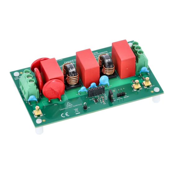
Active EMI Filter Evaluation Module for Single-Phase AC
Power Systems
Description
The
TPSF12C1EVM-FILTER
(EVM) is specifically designed to validate the
performance of the
TPSF12C1
IC. The active EMI filter (AEF) helps to improve
the common-mode (CM) electromagnetic interference
(EMI) signature in single-phase AC power systems by
amplification of the effective Y-capacitance value.
Get Started
1. Order the
TPSF12C1EVM-FILTER
2. Study this EVM user's guide and
3. Use the TPSF12C1
quickstart calculator
with EMI filter design and component selection
4. Prior to connecting the power stage, test the
active filter circuit with a low-voltage signal source
5. Connect the filter to an AC-input power stage and
verify the INJ voltage swing is within limits
6. Measure the total (DM and CM) EMI signature
and use a splitter to isolate the CM contribution
Features
•
Improved CM
EMI performance
with single-phase AC input
– Voltage-sense, current-inject AEF topology
presents low shunt impedance by amplifying
the effective value of Y-capacitance
•
Up to 30 dB reduction in the CM EMI
signature from 100 kHz to 3 MHz
SLVUCQ2A – JULY 2023 – REVISED JULY 2023
Submit Document Feedback
evaluation module
power-supply filter
EVM
PCB layout
files
to assist
for applications
Copyright © 2023 Texas Instruments Incorporated
– A higher effective Y-capacitance enables a
reduction in CM choke size, weight and cost
•
Simple configuration for single-phase AC systems
– Integrated sensing filter and summing network
– Low Y-capacitor line-frequency leakage current
to chassis ground maintains safety
– Simplified compensation network
•
Inherent protection features for reliable design
– Withstands 6-kV+ surge with minimal external
component count
•
Helps meet IEC 61000-4-5 surge immunity
system-level specification
•
Integrated SENSE input surge protection
– Wide VDD supply voltage range of 8 V to 16 V
•
Undervoltage lockout (UVLO) set to turn on
and off at 7.7 V and 6.7 V, respectively
•
The EVM includes a high-PSRR LDO for
step-down regulation to 12 V (if needed)
– 175°C thermal shutdown protection
– Integrated VDD-to-EN pullup allows use of an
open-drain/collector device for disable function
•
Fully assembled, tested and proven two-layer
design
with 5" × 3" (127 mm × 76 mm) total area
Applications
•
On-board charger
for BEVs and PHEVs
•
Power delivery
– high-density
•
Welders and other industrial systems
•
Telecom AC/DC rectifiers
Active EMI Filter Evaluation Module for Single-Phase AC Power Systems
Description
PCB
server rack PSUs
1
Advertisement
Table of Contents

Subscribe to Our Youtube Channel
Related Manuals for Texas Instruments TPSF12C1EVM-FILTER


Summary of Contents for Texas Instruments TPSF12C1EVM-FILTER
- Page 1 Up to 30 dB reduction in the CM EMI signature from 100 kHz to 3 MHz SLVUCQ2A – JULY 2023 – REVISED JULY 2023 Active EMI Filter Evaluation Module for Single-Phase AC Power Systems Submit Document Feedback Copyright © 2023 Texas Instruments Incorporated...
-
Page 2: Specifications
3 MHz. This performance metric can change based on the VDD supply voltage, passive filter component values, active circuit compensation and damping component values, ambient temperature, and other parameters. Active EMI Filter Evaluation Module for Single-Phase AC Power Systems SLVUCQ2A – JULY 2023 – REVISED JULY 2023 Submit Document Feedback Copyright © 2023 Texas Instruments Incorporated... -
Page 3: Device Information
Hot surface. Contact can cause burns. Do not touch. CAUTION High Voltage. Risk of electric shock. SLVUCQ2A – JULY 2023 – REVISED JULY 2023 Active EMI Filter Evaluation Module for Single-Phase AC Power Systems Submit Document Feedback Copyright © 2023 Texas Instruments Incorporated... - Page 4 Evaluation Module Overview www.ti.com General Texas Instruments High Voltage Evaluation (TI HV EVM) User Safety Guidelines WARNING Always follow TI's set-up and application instructions, including use of all interface components within their recommended electrical rated voltage and power limits. Always use electrical safety precautions to help ensure your personal safety and those working around you.
- Page 5 DM and CM noise signatures from the total noise measurement. SLVUCQ2A – JULY 2023 – REVISED JULY 2023 Active EMI Filter Evaluation Module for Single-Phase AC Power Systems Submit Document Feedback Copyright © 2023 Texas Instruments Incorporated...
- Page 6 The setup is essentially agnostic to regulator topology. Active EMI Filter Evaluation Module for Single-Phase AC Power Systems SLVUCQ2A – JULY 2023 – REVISED JULY 2023 Submit Document Feedback Copyright © 2023 Texas Instruments Incorporated...
-
Page 7: Header Information
Working at an ESD-protected workstation, verify that any wrist straps, bootstraps or mats are connected and referencing the user to earth ground before power is applied to the EVM. SLVUCQ2A – JULY 2023 – REVISED JULY 2023 Active EMI Filter Evaluation Module for Single-Phase AC Power Systems Submit Document Feedback Copyright © 2023 Texas Instruments Incorporated... - Page 8 7. Turn the regulator OFF. Wait for all high-voltage capacitors to fully discharge. 8. Power down the IC and remove the VDD supply. Active EMI Filter Evaluation Module for Single-Phase AC Power Systems SLVUCQ2A – JULY 2023 – REVISED JULY 2023 Submit Document Feedback Copyright © 2023 Texas Instruments Incorporated...
- Page 9 (when the gain is positive). Refer to the TPSF12C1 data sheet for guidance on component selection. Check the insertion loss plots with AEF enabled and disabled. SLVUCQ2A – JULY 2023 – REVISED JULY 2023 Active EMI Filter Evaluation Module for Single-Phase AC Power Systems Submit Document Feedback Copyright © 2023 Texas Instruments Incorporated...
- Page 10 Measure the total EMI. Separate the CM (asymmetrical) and DM (symmetrical) propagation components, as the TPSF12C1-based AEF circuit only attenuates the CM noise. Active EMI Filter Evaluation Module for Single-Phase AC Power Systems SLVUCQ2A – JULY 2023 – REVISED JULY 2023 Submit Document Feedback Copyright © 2023 Texas Instruments Incorporated...
- Page 11 For additional context pertaining to component selection and circuit optimization, refer to the TPSF12C1 product data sheet and the TPSF12C1 quickstart calculator. SLVUCQ2A – JULY 2023 – REVISED JULY 2023 Active EMI Filter Evaluation Module for Single-Phase AC Power Systems Submit Document Feedback Copyright © 2023 Texas Instruments Incorporated...
-
Page 12: Emi Performance
TPSF12C1 device run at 28°C and 12°C above the local ambient temperature, respectively. Figure 3-2. Thermal Image at 10-A Load Active EMI Filter Evaluation Module for Single-Phase AC Power Systems SLVUCQ2A – JULY 2023 – REVISED JULY 2023 Submit Document Feedback Copyright © 2023 Texas Instruments Incorporated... -
Page 13: Surge Immunity
Figure 3-5. IEC 61000-4-5 Surge, 6-kV Repetitive Strike at 10-Second Intervals – Positive (a), Negative (b) SLVUCQ2A – JULY 2023 – REVISED JULY 2023 Active EMI Filter Evaluation Module for Single-Phase AC Power Systems Submit Document Feedback Copyright © 2023 Texas Instruments Incorporated... -
Page 14: Insertion Loss
10000 Frequency (kHz) Figure 3-8. Typical Insertion Loss with AEF Enabled and Disabled Active EMI Filter Evaluation Module for Single-Phase AC Power Systems SLVUCQ2A – JULY 2023 – REVISED JULY 2023 Submit Document Feedback Copyright © 2023 Texas Instruments Incorporated... - Page 15 Figure 3-9. Impedance Characteristics of the Selected CM Chokes in the Passive Design (2 × 12 mH) and the Active Design (2 × 2 mH) SLVUCQ2A – JULY 2023 – REVISED JULY 2023 Active EMI Filter Evaluation Module for Single-Phase AC Power Systems Submit Document Feedback Copyright © 2023 Texas Instruments Incorporated...
- Page 16 – Texas Instruments, How a stand-alone active EMI filter IC shrinks common-mode filter size Active EMI Filter Evaluation Module for Single-Phase AC Power Systems SLVUCQ2A – JULY 2023 – REVISED JULY 2023 Submit Document Feedback Copyright © 2023 Texas Instruments Incorporated...
- Page 17 Hardware Design Files 4.1 Schematic Figure 4-1 provides the EVM schematic. Figure 4-1. EVM Schematic SLVUCQ2A – JULY 2023 – REVISED JULY 2023 Active EMI Filter Evaluation Module for Single-Phase AC Power Systems Submit Document Feedback Copyright © 2023 Texas Instruments Incorporated...
- Page 18 TPS7A4901 36 V, 150 mA LDO with high PSRR MSOP (8) TPS7A4901DGNR Texas Instruments Active EMI Filter Evaluation Module for Single-Phase AC Power Systems SLVUCQ2A – JULY 2023 – REVISED JULY 2023 Submit Document Feedback Copyright © 2023 Texas Instruments Incorporated...
-
Page 19: Pcb Layout
Figure 4-2. 3D Top View Figure 4-3. 3D Bottom View SLVUCQ2A – JULY 2023 – REVISED JULY 2023 Active EMI Filter Evaluation Module for Single-Phase AC Power Systems Submit Document Feedback Copyright © 2023 Texas Instruments Incorporated... - Page 20 Figure 4-4. Top Layer Copper Figure 4-5. Bottom Layer Copper (Viewed From Top) Active EMI Filter Evaluation Module for Single-Phase AC Power Systems SLVUCQ2A – JULY 2023 – REVISED JULY 2023 Submit Document Feedback Copyright © 2023 Texas Instruments Incorporated...
-
Page 21: Assembly Drawings
4.3.1 Assembly Drawings Figure 4-6. Top Assembly (Top View) Figure 4-7. Bottom Assembly (Bottom View) SLVUCQ2A – JULY 2023 – REVISED JULY 2023 Active EMI Filter Evaluation Module for Single-Phase AC Power Systems Submit Document Feedback Copyright © 2023 Texas Instruments Incorporated... -
Page 22: Compliance Information
4.3.2 Multi-Layer Stackup Figure 4-8. Layer Stackup 5 Compliance Information 5.1 Compliance and Certifications • TPSF12C1EVM-FILTER EU Declaration of Conformity (DoC) for Restricting the use of Hazardous Substances (RoHS) 6 Additional Information Trademarks All trademarks are the property of their respective owners. - Page 23 TI products. TI’s provision of these resources does not expand or otherwise alter TI’s applicable warranties or warranty disclaimers for TI products. TI objects to and rejects any additional or different terms you may have proposed. IMPORTANT NOTICE Mailing Address: Texas Instruments, Post Office Box 655303, Dallas, Texas 75265 Copyright © 2023, Texas Instruments Incorporated...
Need help?
Do you have a question about the TPSF12C1EVM-FILTER and is the answer not in the manual?
Questions and answers