Table of Contents
Advertisement
Quick Links
TPS563231EVM-032 3-A, Synchronous Step-down
This user's guide contains information for the TPS563231 as well as support documentation for the
TPS563231EVM-032 evaluation module. Included are the performance specifications, schematic, and the
bill of materials of the TPS563231EVM-032.
...................................................................................................................
1
2
3
3.1
4
4.1
4.2
4.3
4.4
4.5
4.6
4.7
4.8
4.9
4.10
5
5.1
6
6.1
6.2
6.3
1
2
3
4
5
6
TPS563231EVM-032 Output Voltage Ripple, I
7
TPS563231EVM-032 Output Voltage Ripple, I
8
TPS563231EVM-032 Output Voltage Ripple, I
9
TPS563231EVM-032 Input Voltage Ripple, I
10
TPS563231EVM-032 Start-Up Relative to V
11
12
TPS563231EVM-032 Shut-Down Relative to V
13
14
...................................................................................................................
15
SLUUBT7A - July 2018 - Revised December 2018
Submit Documentation Feedback
.....................................................................................
..................................................................................................................
............................................................................................
.....................................................................................................
..........................................................................................
.................................................................................................
.............................................................................................................
.....................................................................................................
.....................................................................................................
.........................................................................................
..............................................................................................
................................................................................................
.............................................................................................................
.........................................................................................................
................................................................................................................
...............................................................................................................
..........................................................................................................
....................................................................................................
..........................................................................................................
...........................................................................................
...................................................................................
....................................................................................
...............................................................................................................
TPS563231EVM-032 3-A, Synchronous Step-down Converter Evaluation
Copyright © 2018, Texas Instruments Incorporated
SLUUBT7A - July 2018 - Revised December 2018
Converter Evaluation Module
Contents
............................................................................
List of Figures
..............................................................................
................................................................
..........................................................
.............................................................
..................................................................
..........................................................................
IN
.........................................................................
......................................................................
IN
......................................................................
User's Guide
..........................................
Module
2
2
3
3
4
4
4
5
6
7
7
8
9
10
11
12
12
14
14
15
15
5
5
6
7
7
8
8
9
9
10
10
11
11
12
13
1
Advertisement
Table of Contents

Subscribe to Our Youtube Channel
Related Manuals for Texas Instruments TPS563231EVM-032


Summary of Contents for Texas Instruments TPS563231EVM-032
-
Page 1: Table Of Contents
TPS563231EVM-032 3-A, Synchronous Step-down Converter Evaluation Module This user's guide contains information for the TPS563231 as well as support documentation for the TPS563231EVM-032 evaluation module. Included are the performance specifications, schematic, and the bill of materials of the TPS563231EVM-032. Contents ........................ -
Page 2: Introduction
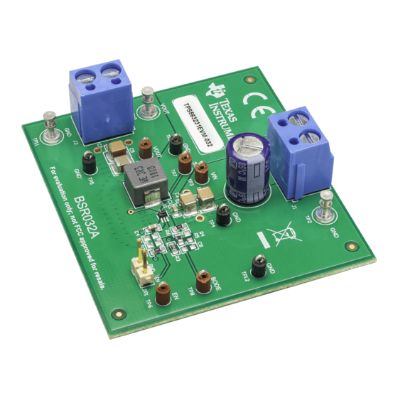
Table The TPS563231EVM-032 evaluation module (EVM) is a single, synchronous buck converter providing 3.3 V at 3 A from 4.5-V to 17-V input. This user’s guide describes the TPS563231EVM-032 performance. Table 1. Input Voltage and Output Current Summary INPUT VOLTAGE RANGE... -
Page 3: Modifications
20 - 68 45.3 10.0 20 - 68 73.2 10.0 20 - 68 98.3 10.0 20 - 68 SLUUBT7A – July 2018 – Revised December 2018 TPS563231EVM-032 3-A, Synchronous Step-down Converter Evaluation Module Submit Documentation Feedback Copyright © 2018, Texas Instruments Incorporated... -
Page 4: Test Setup And Results
Test Setup and Results This section describes how to properly connect, set up, and use the TPS563231EVM-032. The section also includes test results typical for the evaluation modules and efficiency, output load regulation, output line regulation, load transient response, output voltage ripple, input voltage ripple, start-up, and switching frequency. -
Page 5: Efficiency
= 5V = 12V = 17V Output Current - A D01_ Figure 1. TPS563231EVM-032 Efficiency Figure 2 shows the efficiency at light loads for the TPS563231EVM-032 at an ambient temperature of 25°C. = 5V = 12V = 17V 0.001 0.01... -
Page 6: Load Regulation
Test Setup and Results www.ti.com Load Regulation The load regulation for the TPS563231EVM-032 is shown in Figure = 5V = 12V = 17V -0.5 -1.5 Output Current - A D03_ Figure 3. TPS563231EVM-032 Load Regulation TPS563231EVM-032 3-A, Synchronous Step-down Converter Evaluation SLUUBT7A –... -
Page 7: Line Regulation
Load Step = 0.75 A t 2.25 A , Slew Rate = 500 mA / s 200 s / div Figure 5. TPS563231EVM-032 Load Transient Response, 25% to 75% Load Step SLUUBT7A – July 2018 – Revised December 2018 TPS563231EVM-032 3-A, Synchronous Step-down Converter Evaluation... -
Page 8: Output Voltage Ripple
Test Setup and Results www.ti.com Output Voltage Ripple The TPS563231EVM-032 output voltage ripple is shown in Figure Figure 7, and Figure 8. The output currents are as indicated. Vout = 20 mV / div (AC coupled) SW = 5 V / div 1 s / div Figure 6. -
Page 9: Input Voltage Ripple
1 s / div Figure 8. TPS563231EVM-032 Output Voltage Ripple, I = 0 mA Input Voltage Ripple The TPS563231EVM-032 input voltage ripple is shown in Figure 9. The output current is as indicated. Vin = 50 mV / div (AC coupled) -
Page 10: Start-Up
EN = 3 V / div Vout = 1 V / div 2 ms / div Figure 10. TPS563231EVM-032 Start-Up Relative to V The TPS563231EVM-032 start-up waveform relative to enable (EN) is shown in Figure 11. Load = 2 Ω resistive. -
Page 11: 4.10 Shut-Down
Vout = 1 V / div 2 ms / div Figure 12. TPS563231EVM-032 Shut-Down Relative to V The TPS563231EVM-032 shut-down waveform relative to EN is shown in Figure 13. Load = 2 Ω resistive. Vin = 5 V / div... -
Page 12: Board Layout
Board Layout www.ti.com Board Layout This section provides a description of the TPS563231EVM-032, board layout, and layer illustrations. Layout The board layout for the TPS563231EVM-032 is shown in Figure Figure 15 Figure 16. The top layer contains the main power traces for VIN, VOUT, and ground. Also on the top layer are connections for the pins of the TPS563231 and a large area filled with ground. -
Page 13: Top Layer
Board Layout www.ti.com Figure 15. Top Layer Figure 16. Bottom Layer SLUUBT7A – July 2018 – Revised December 2018 TPS563231EVM-032 3-A, Synchronous Step-down Converter Evaluation Module Submit Documentation Feedback Copyright © 2018, Texas Instruments Incorporated... -
Page 14: Schematic, Bill Of Materials, And Reference
Schematic, Bill of Materials, and Reference www.ti.com Schematic, Bill of Materials, and Reference Schematic Figure 17 is the schematic for the TPS563231EVM-032. Figure 17. TPS563231EVM-032 Schematic Diagram TPS563231EVM-032 3-A, Synchronous Step-down Converter Evaluation SLUUBT7A – July 2018 – Revised December 2018 Module Submit Documentation Feedback Copyright ©... -
Page 15: List Of Materials
1. TPS56323x 4.5 V to 17 V Input, 3-A Synchronous Step-Down Voltage Regulator in SOT563 data sheet (SLUSD65) Trademarks D-CAP3 is a trademark of Texas Instruments. SLUUBT7A – July 2018 – Revised December 2018 TPS563231EVM-032 3-A, Synchronous Step-down Converter Evaluation... - Page 16 Figure 2 TPS563231EVM-032 Light Load Efficiency ................• Changed Figure 3 TPS563231EVM-032 Load Regulation ................• Changed Figure 4 TPS563231EVM-032 Line Regulation Revision History SLUUBT7A – July 2018 – Revised December 2018 Submit Documentation Feedback Copyright © 2018, Texas Instruments Incorporated...
- Page 17 STANDARD TERMS FOR EVALUATION MODULES Delivery: TI delivers TI evaluation boards, kits, or modules, including any accompanying demonstration software, components, and/or documentation which may be provided together or separately (collectively, an “EVM” or “EVMs”) to the User (“User”) in accordance with the terms set forth herein.
- Page 18 FCC Interference Statement for Class B EVM devices NOTE: This equipment has been tested and found to comply with the limits for a Class B digital device, pursuant to part 15 of the FCC Rules. These limits are designed to provide reasonable protection against harmful interference in a residential installation.
- Page 19 【無線電波を送信する製品の開発キットをお使いになる際の注意事項】 開発キットの中には技術基準適合証明を受けて いないものがあります。 技術適合証明を受けていないもののご使用に際しては、電波法遵守のため、以下のいずれかの 措置を取っていただく必要がありますのでご注意ください。 1. 電波法施行規則第6条第1項第1号に基づく平成18年3月28日総務省告示第173号で定められた電波暗室等の試験設備でご使用 いただく。 2. 実験局の免許を取得後ご使用いただく。 3. 技術基準適合証明を取得後ご使用いただく。 なお、本製品は、上記の「ご使用にあたっての注意」を譲渡先、移転先に通知しない限り、譲渡、移転できないものとします。 上記を遵守頂けない場合は、電波法の罰則が適用される可能性があることをご留意ください。 日本テキサス・イ ンスツルメンツ株式会社 東京都新宿区西新宿6丁目24番1号 西新宿三井ビル 3.3.3 Notice for EVMs for Power Line Communication: Please see http://www.tij.co.jp/lsds/ti_ja/general/eStore/notice_02.page 電力線搬送波通信についての開発キットをお使いになる際の注意事項については、次のところをご覧ください。http:/ /www.tij.co.jp/lsds/ti_ja/general/eStore/notice_02.page 3.4 European Union 3.4.1 For EVMs subject to EU Directive 2014/30/EU (Electromagnetic Compatibility Directive): This is a class A product intended for use in environments other than domestic environments that are connected to a low-voltage power-supply network that supplies buildings used for domestic purposes.
- Page 20 Notwithstanding the foregoing, any judgment may be enforced in any United States or foreign court, and TI may seek injunctive relief in any United States or foreign court. Mailing Address: Texas Instruments, Post Office Box 655303, Dallas, Texas 75265 Copyright © 2018, Texas Instruments Incorporated...
- Page 21 TI products. TI’s provision of these resources does not expand or otherwise alter TI’s applicable warranties or warranty disclaimers for TI products. Mailing Address: Texas Instruments, Post Office Box 655303, Dallas, Texas 75265 Copyright © 2018, Texas Instruments Incorporated...
Need help?
Do you have a question about the TPS563231EVM-032 and is the answer not in the manual?
Questions and answers