Table of Contents
Advertisement
Quick Links
www.ti.com
EVM User's Guide: TPSF12C1QEVM
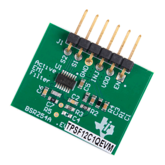
Active EMI Filter Evaluation Module for Single-Phase AC
Power Systems
Description
The
TPSF12C1QEVM
evaluation module (EVM) is
specifically designed to validate the performance of
the
TPSF12C1
power-supply filter IC. The active EMI
filter (AEF) helps to improve the common-mode (CM)
electromagnetic interference (EMI) signature in single-
phase AC power systems by amplification of the
effective Y-capacitance value.
Get Started
1. Order the
TPSF12C1QEVM
2. Study this EVM user's guide and
3. Use the TPSF12C1
quickstart calculator
with EMI filter design and component selection
4. Prior to connecting the power stage, test the
active filter circuit with a low-voltage signal source
5. Connect the filter to an AC-input power stage and
verify the INJ (pin 13) voltage swing is within limits
6. Measure the total (DM and CM) EMI signature
and use a splitter to isolate the CM contribution
Features
•
Improved CM
EMI performance
with single-phase AC input
– Helps to meet EMI standards, such as CISPR
11, 25 or 32
– Voltage-sense, current-inject AEF topology
presents low shunt impedance to ground
•
Up to 30 dB reduction in the CM EMI
signature from 100 kHz to 3 MHz
SLVUCK7A – NOVEMBER 2022 – REVISED JULY 2023
Submit Document Feedback
EVM
PCB layout
files
to assist
for applications
Active EMI Filter Evaluation Module for Single-Phase AC Power Systems
Copyright © 2023 Texas Instruments Incorporated
– A higher effective Y-capacitance enables a
reduction in CM choke size, weight and cost
– No additional magnetic components required
•
Simple configuration for single-phase AC systems
– Integrated sensing filter and summing network
– Low Y-capacitor line-frequency leakage current
to chassis ground maintains safety
– Simplified compensation and damping network
•
Inherent protection features for reliable design
– Withstands 6-kV+ surge with minimal external
component count
•
Helps meet IEC 61000-4-5 surge immunity
system-level specification
•
Integrated SENSE input surge protection
– Wide VDD supply voltage range of 8 V to 16 V
•
Undervoltage lockout (UVLO) set to turn on
and off at 7.7 V and 6.7 V, respectively
•
Quiescent supply current of 12.5 mA
– 175°C thermal shutdown protection
– Integrated VDD-to-EN pullup allows use of an
open-drain/collector device for disable function
•
Fully assembled, tested and proven four-layer
PCB design
with 1" × 0.8" (25 mm × 20 mm) total
area
Applications
•
On-board charger
for BEVs and PHEVs
•
Power delivery
– high-density
•
Welders and other industrial systems
•
Telecom AC/DC rectifiers
Description
server rack PSUs
1
Advertisement
Table of Contents

Related Manuals for Texas Instruments TPSF12C1QEVM


Summary of Contents for Texas Instruments TPSF12C1QEVM
- Page 1 Up to 30 dB reduction in the CM EMI signature from 100 kHz to 3 MHz SLVUCK7A – NOVEMBER 2022 – REVISED JULY 2023 Active EMI Filter Evaluation Module for Single-Phase AC Power Systems Submit Document Feedback Copyright © 2023 Texas Instruments Incorporated...
-
Page 2: Specifications
The deployment of active filter circuits enable more compact filters for next-generation power conversion systems. Active EMI Filter Evaluation Module for Single-Phase AC Power Systems SLVUCK7A – NOVEMBER 2022 – REVISED JULY 2023 Submit Document Feedback Copyright © 2023 Texas Instruments Incorporated... - Page 3 This helps to meet surge specifications such as IEC 61000-4-5. SLVUCK7A – NOVEMBER 2022 – REVISED JULY 2023 Active EMI Filter Evaluation Module for Single-Phase AC Power Systems Submit Document Feedback Copyright © 2023 Texas Instruments Incorporated...
- Page 4 2 Hardware 2.1 EVM Description The TPSF12C1QEVM, a daughter-card design that attaches to an existing passive EMI filter circuit in a single- phase AC power system, showcases the CM EMI performance improvement or size reduction achievable with the TPSF12C1, a single-phase power-supply filter IC.
- Page 5 EVM header J1 can mount directly to receptacle J2. SLVUCK7A – NOVEMBER 2022 – REVISED JULY 2023 Active EMI Filter Evaluation Module for Single-Phase AC Power Systems Submit Document Feedback Copyright © 2023 Texas Instruments Incorporated...
- Page 6 TI standalone active EMI filter EVM Figure 2-4. EVM Setup Schematic for Low-Voltage Testing Active EMI Filter Evaluation Module for Single-Phase AC Power Systems SLVUCK7A – NOVEMBER 2022 – REVISED JULY 2023 Submit Document Feedback Copyright © 2023 Texas Instruments Incorporated...
-
Page 7: Header Information
10. Turn the regulator OFF. Wait for all high-voltage capacitors to fully discharge. SLVUCK7A – NOVEMBER 2022 – REVISED JULY 2023 Active EMI Filter Evaluation Module for Single-Phase AC Power Systems Submit Document Feedback Copyright © 2023 Texas Instruments Incorporated... - Page 8 (when the gain is positive). Refer to the TPSF12C1 data sheet for guidance on component selection. Check the insertion loss plots with AEF enabled and disabled. Active EMI Filter Evaluation Module for Single-Phase AC Power Systems SLVUCK7A – NOVEMBER 2022 – REVISED JULY 2023 Submit Document Feedback Copyright © 2023 Texas Instruments Incorporated...
- Page 9 Measure the total EMI. Separate the CM (asymmetrical) and DM (symmetrical) propagation components, as the TPSF12C1-based AEF circuit only attenuates the CM noise. SLVUCK7A – NOVEMBER 2022 – REVISED JULY 2023 Active EMI Filter Evaluation Module for Single-Phase AC Power Systems Submit Document Feedback Copyright © 2023 Texas Instruments Incorporated...
- Page 10 For additional context pertaining to component selection and circuit optimization, refer to the TPSF12C1 product data sheet and the TPSF12C1 quickstart calculator. Active EMI Filter Evaluation Module for Single-Phase AC Power Systems SLVUCK7A – NOVEMBER 2022 – REVISED JULY 2023 Submit Document Feedback Copyright © 2023 Texas Instruments Incorporated...
-
Page 11: Emi Performance
Figure 3-2. Thermal Image of an Active Filter Design at 10-A Load, 27°C Ambient SLVUCK7A – NOVEMBER 2022 – REVISED JULY 2023 Active EMI Filter Evaluation Module for Single-Phase AC Power Systems Submit Document Feedback Copyright © 2023 Texas Instruments Incorporated... -
Page 12: Surge Immunity
Figure 3-5. IEC 61000-4-5 Surge, 6-kV Repetitive Strike at 10-Second Intervals – Positive (a), Negative (b) Active EMI Filter Evaluation Module for Single-Phase AC Power Systems SLVUCK7A – NOVEMBER 2022 – REVISED JULY 2023 Submit Document Feedback Copyright © 2023 Texas Instruments Incorporated... -
Page 13: Insertion Loss
10000 Frequency (kHz) Figure 3-8. Typical Insertion Loss with AEF Enabled and Disabled SLVUCK7A – NOVEMBER 2022 – REVISED JULY 2023 Active EMI Filter Evaluation Module for Single-Phase AC Power Systems Submit Document Feedback Copyright © 2023 Texas Instruments Incorporated... - Page 14 REFGND 10nF TPSF12C1QDYY RQ1 IGND IGND COMP2 1.50k 0603 Figure 4-1. EVM Schematic Active EMI Filter Evaluation Module for Single-Phase AC Power Systems SLVUCK7A – NOVEMBER 2022 – REVISED JULY 2023 Submit Document Feedback Copyright © 2023 Texas Instruments Incorporated...
- Page 15 CAP, FILM, 4.7 nF, 300 VAC, Y2 13 × 5 mm R413F147050T1K Kemet SLVUCK7A – NOVEMBER 2022 – REVISED JULY 2023 Active EMI Filter Evaluation Module for Single-Phase AC Power Systems Submit Document Feedback Copyright © 2023 Texas Instruments Incorporated...
- Page 16 The PCB is 62-mils standard thickness with 1-oz copper on all layers. Figure 4-2. 3D Top View Figure 4-3. 3D Bottom View Active EMI Filter Evaluation Module for Single-Phase AC Power Systems SLVUCK7A – NOVEMBER 2022 – REVISED JULY 2023 Submit Document Feedback Copyright © 2023 Texas Instruments Incorporated...
- Page 17 Hardware Design Files Figure 4-4. Top Layer Copper Figure 4-5. Layer 2 Copper SLVUCK7A – NOVEMBER 2022 – REVISED JULY 2023 Active EMI Filter Evaluation Module for Single-Phase AC Power Systems Submit Document Feedback Copyright © 2023 Texas Instruments Incorporated...
- Page 18 Figure 4-6. Layer 3 Copper Figure 4-7. Bottom Layer Copper (Viewed From Top) Active EMI Filter Evaluation Module for Single-Phase AC Power Systems SLVUCK7A – NOVEMBER 2022 – REVISED JULY 2023 Submit Document Feedback Copyright © 2023 Texas Instruments Incorporated...
-
Page 19: Assembly Drawings
4.3.1 Assembly Drawings Figure 4-8. Top Assembly (Top View) Figure 4-9. Bottom Assembly (Bottom View) SLVUCK7A – NOVEMBER 2022 – REVISED JULY 2023 Active EMI Filter Evaluation Module for Single-Phase AC Power Systems Submit Document Feedback Copyright © 2023 Texas Instruments Incorporated... -
Page 20: Compliance Information
4.3.2 Multi-Layer Stackup Figure 4-10. Layer Stackup 5 Compliance Information 5.1 Compliance and Certifications • TPSF12C1QEVM EU Declaration of Conformity (DoC) for Restricting the use of Hazardous Substances (RoHS) 6 Additional Information Trademarks All trademarks are the property of their respective owners. - Page 21 • Added SENSE and INJ Voltages ........................13 • Added insertion loss plot..........................SLVUCK7A – NOVEMBER 2022 – REVISED JULY 2023 Active EMI Filter Evaluation Module for Single-Phase AC Power Systems Submit Document Feedback Copyright © 2023 Texas Instruments Incorporated...
- Page 22 STANDARD TERMS FOR EVALUATION MODULES Delivery: TI delivers TI evaluation boards, kits, or modules, including any accompanying demonstration software, components, and/or documentation which may be provided together or separately (collectively, an “EVM” or “EVMs”) to the User (“User”) in accordance with the terms set forth herein.
- Page 23 www.ti.com Regulatory Notices: 3.1 United States 3.1.1 Notice applicable to EVMs not FCC-Approved: FCC NOTICE: This kit is designed to allow product developers to evaluate electronic components, circuitry, or software associated with the kit to determine whether to incorporate such items in a finished product and software developers to write software applications for use with the end product.
- Page 24 www.ti.com Concernant les EVMs avec antennes détachables Conformément à la réglementation d'Industrie Canada, le présent émetteur radio peut fonctionner avec une antenne d'un type et d'un gain maximal (ou inférieur) approuvé pour l'émetteur par Industrie Canada. Dans le but de réduire les risques de brouillage radioélectrique à...
- Page 25 www.ti.com EVM Use Restrictions and Warnings: 4.1 EVMS ARE NOT FOR USE IN FUNCTIONAL SAFETY AND/OR SAFETY CRITICAL EVALUATIONS, INCLUDING BUT NOT LIMITED TO EVALUATIONS OF LIFE SUPPORT APPLICATIONS. 4.2 User must read and apply the user guide and other available documentation provided by TI regarding the EVM prior to handling or using the EVM, including without limitation any warning or restriction notices.
- Page 26 Notwithstanding the foregoing, any judgment may be enforced in any United States or foreign court, and TI may seek injunctive relief in any United States or foreign court. Mailing Address: Texas Instruments, Post Office Box 655303, Dallas, Texas 75265 Copyright © 2023, Texas Instruments Incorporated...
-
Page 27: Important Notice
TI products. TI’s provision of these resources does not expand or otherwise alter TI’s applicable warranties or warranty disclaimers for TI products. TI objects to and rejects any additional or different terms you may have proposed. IMPORTANT NOTICE Mailing Address: Texas Instruments, Post Office Box 655303, Dallas, Texas 75265 Copyright © 2023, Texas Instruments Incorporated...
Need help?
Do you have a question about the TPSF12C1QEVM and is the answer not in the manual?
Questions and answers