
Related Manuals for Pro Spot DRAWN ARC PS-DA5


Summary of Contents for Pro Spot DRAWN ARC PS-DA5
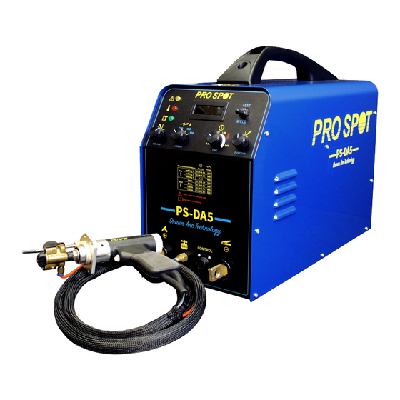
- Page 1 DRAWN ARC DRAWN ARC PS-DA5 PS-DA5 Instruction Manual MNL-PS-DA5-v1.0 All Info Copyright © Pro Spot International Inc. All Info Copyright © Pro Spot International Inc.
- Page 2 & development department, a fabrication facility and production lines for the various welders Pro Spot International exports its products worldwide, export sales are managed through our headquarter office. The company owns numerous patents for our ingenious application tools, machines, and procedures.
-
Page 3: Table Of Contents
3.1 Setup 3.2 Input Power Connections 3.3 Description of Control 4.0 DESCRIPTION OF PS-DA5 WELDING TORCH 5.0 OPERATION 5.1 Torch & Ground Cable Connection 5.2 Key Welding 5.3 Stud Welding 6.0 TROUBLESHOOTING All Info Copyright © Pro Spot International Inc. -
Page 4: Safety
• Keep focused and alert while operating the device. Never use it when you are tired or under the in uence of medication or alcohol. • Wear slip-proof gloves and tinted glasses while operating the device. • Serious injury may occur. All Info Copyright © Pro Spot International Inc. -
Page 5: Safety Precautions
SAFETY IMPORTANT: BEFORE STARTING THE EQUIPMENT, READ THE CONTENTS OF THIS MANUAL, WHICH MUST BE STORED IN A PLACE FAMILIAR TO ALL USERS FOR THE ENTIRE OPERATIVE LIFE-SPAN OF THE MACHINE. THIS EQUIPMENT MUST BE USED SOLELY FOR WELDING OPERATIONS. SAFETY PRECAUTIONS WELDING AND ARC CUTTING CAN BE HARMFUL TO YOURSELF AND OTHERS. -
Page 6: General Technical Description
TECHNICAL DESCRIPTION 2.0 GENERAL TECHNICAL DESCRIPTIONS 2.1 SPECIFICATIONS This manual has been prepared with the intent of instructing the operator on how to install, operate, and properly maintain this electric arc welding machine. This machine is a constant current power source for MMA welding. Upon receiving and unpacking the machine, make a careful inspection to ensure that there are no damaged parts. -
Page 7: Installation
INSTALLATION 3.0 INSTALLATION 3.1 SETUP Place the machine in a ventilated area. Dust, dirt, or any other foreign material that might enter the machine may restrict the ventilation which could affect the machine’s performance. 3.2 INPUT POWER CONNECTIONS All sections concerning the installation of this machine must be read carefully. This machine must be installed by authorized personnel. - Page 8 PS-DA5 FRONT PANEL Function Description Meter Display: (1)Welding time: 0.01~2.00 sec。 (2)Welding current: PS-DA500 = 250/300/400/500 A (3)Error code:E01~E08。 (4)Test mode:“tSt”。 Warning When the machine is abnormal, the warning indicator will light up. indicator Please check the machine problem, refer to the error code E01-E08. E01: Torch trigger is on, before turning on the machine.
-
Page 9: Description Of Ps-Da5 Welding Torch
WELDING TORCH 4.0 DESCRIPTION OF PS-DA5 WELDING TORCH Item Function Description Clockwise rotation--- reduce the distance. Adjust Counter clockwise electrode rotation---increase the distance. pulled Refer to the red area is showing distance. the distance. (washer or Note: Too long pulled distance stud) may lead to the solenoid to not work normally. - Page 10 WELDING PARAMETERS 5.0 SUGGESTED WELDING PARAMETER The following parameters are for reference only, subject to the actual welding situation. Key extension, key pulled distance, welding current, and welding time are main parameters for aluminum key welding. Adjustment suggestions as follows: 1) Gas flow: 6~7 L/min (pre-flow time and post-flow time are not major factors).
-
Page 11: Torch & Ground Cable Connection
TORCH & GROUND CABLE CONNECTION Torch & ground cable connection: Torch Connected Ground Connected Ground Connected Torch Connected Positive + Positive + Negative - Negative - (Recommended) Torch + / Ground - Torch - / Ground + Tension Strength Easy-to-use Surface clean Allowable... -
Page 12: Key Welding
KEY WELDING 2. Installing Key Torch Head 1. Install Support Leg Adapter 1. Insert torch head into the gun. 1. Install leg adapter on the gun. 2. Tighten the retaining nut with the appropriate 2. Hand tighten knurled nut to secure the leg adapter. size wrench. - Page 13 KEY WELDING 7. Support Leg Height (Single Leg or Dual Leg): 8. Use a stainless steel brush to clean surface just before 1. Insert weld key into the torch head. welding. Push gun down so the support legs touch the 2.
-
Page 14: Stud Welding
STUD WELDING 2. Installing Stud Torch Head 1. Install Support Leg Adapter 1. Insert stud torch head into the gun. 1. Install leg adapter on the gun. 2. Tighten the retaining nut with the appropriate 2. Hand tighten knurled nut to secure the leg adapter. size wrench. - Page 15 STUD WELDING 7. Adjusting Lifting Height of the Torch Head 8. Support Leg Height: 1. Insert stud into the torch head. 2. Place the stud in location to be welded. 3. Adjust support legs to 1mm away from panel putting downward pressure on the gun. Make sure the stud is weled 90°...
-
Page 16: Troubleshooting
TROUBLE SHOOTING 6.0 TROUBLESHOOTING AL panel repair (380V) Cause Remedy Code Torch trigger is on, before turning on the Don’t trigger on, before turning on the machine. machine. Output terminals are short circuit, Don’t short circuit the output terminals, before turning on the machine. before turning on the machine. - Page 17 TROUBLE SHOOTING DIAGRAM 1 PS-DA5 PS-DA5 Vref -> Iout Vref -> Iout 7.14V -> 488A 11.54V -> 800A 5.88V -> 400A 8.8V -> 600A 4.40V -> 300A 5.88V -> 400A 3.67V -> 250A 3.67V -> 250A Q1: Welding torch cannot work Remove torch head, setting the pulled distance to lowest.
- Page 18 NOTES...
- Page 19 NOTES...
- Page 20 Pro Spot International, Inc. 5932 Sea Otter Place Carlsbad, CA 92010 Toll Free: (877) PRO SPOT Phone: (760) 407-1414 Fax: (760) 407-1421 E-mail: info@prospot.com Web: www.prospot.com Copyright © Pro Spot International, Inc. 2016...
Need help?
Do you have a question about the DRAWN ARC PS-DA5 and is the answer not in the manual?
Questions and answers