Table of Contents
Advertisement
Quick Links
Advertisement
Table of Contents

Related Manuals for Fluke VT Plus HF


Summary of Contents for Fluke VT Plus HF
- Page 1 VT Plus HF Gas Flow Analyzer Operators Manual PN 2137275 May 2008, Rev. 1 © 2008 Fluke Corporation, All rights reserved. Printed in USA. Specifications are subject to change without notice. All product names are trademarks of their respective companies.
- Page 2 Fluke Biomedical. This warranty covers the original purchaser only and is not transferable. The warranty does not apply if the product has been damaged by accident or misuse or has been serviced or modified by anyone other than an authorized Fluke Biomedical service facility.
- Page 3 Copyright Release Fluke Biomedical agrees to a limited copyright release that allows you to reproduce manuals and other printed materials for use in service training programs and other technical publications. If you would like other reproductions or distributions, submit a written request to Fluke Biomedical.
- Page 4 No responsibility is assumed by Fluke Biomedical for the use or reliability of software or equipment that is not supplied by Fluke Biomedical, or by its affiliated dealers.
-
Page 5: Table Of Contents
Table of Contents Chapter Title Page Introduction and Specifications............1-1 Introduction......................1-3 Key Features ...................... 1-3 Unpacking and Inspection.................. 1-3 General Safety Considerations................1-4 Symbols ......................1-4 Warnings and Cautions.................. 1-4 Instrument Familiarity ..................1-5 Front Panel..................... 1-6 Right Panel ....................1-6 Rear Panel...................... - Page 6 VT Plus HF Operators Manual Gas Temperature ..................2-9 Ambient Temperature ................2-9 Relative Humidity ..................2-9 Correction Mode.................... 2-10 Barometric Pressure..................2-10 Breath Detection.................... 2-11 Inspiratory/Expiratory Tidal Volumes............2-12 Zero Mode ..................... 2-12 Setting Analyzer Operating Parameters............. 2-13 Time....................... 2-13 Date .......................
- Page 7 (continued) Contents Low Pressure Screen ..................3-14 Airway Pressure Screen................. 3-15 Volume Screen....................3-16 Oxygen Screen....................3-17 Full Breath Parameters Test Screen ..............3-18 Monitor Screen ....................3-19 Units of Measure....................3-20 Special Functions....................3-21 Trend Test...................... 3-21 Leak Test ....................... 3-24 Stacked Volume Test..................
- Page 8 VT Plus HF Operators Manual Other Setup Functions ..................4-31 Breath Detect ....................4-31 Breath Detect Threshold................4-31 Gas Settings ....................4-31 Barometric Pressure..................4-34 Maintenance, Service, and Calibration..........5-1 Maintenance....................... 5-3 Avoiding Damage..................5-3 Cleaning......................5-3 Oxygen Sensor Replacement ................5-3 Fuse Replacement ....................
- Page 9 List of Tables Table Title Page 1-1. Symbols........................1-4 1-2. Front Panel Components ..................1-6 1-3. Right Panel Components..................1-6 1-4. Back Panel Components ..................1-7 1-5. Left Panel Components ..................1-7 1-6. Front Panel Functions .................... 1-8 1-7. Breath Parameter Accuracy Specifications ............1-13 1-8.
- Page 10 VT Plus HF Operators Manual...
- Page 11 List of Figures Figure Title Page 1-1. Front and Right Analyzer Panels ................1-5 1-2. Rear and Left Analyzer Panels................1-7 1-3. Analyzer Front Panel....................1-8 2-1. Connecting the Analyzer in a Bi-Directional Flow Mode ........2-4 2-2. Connecting the Analyzer to the Inspiratory Limb of the Breathing Circuit... 2-5 2-3.
- Page 12 VT Plus HF Operators Manual viii...
- Page 13 Chapter 1 Introduction and Specifications Title Page Introduction......................1-3 Key Features ...................... 1-3 Unpacking and Inspection.................. 1-3 General Safety Considerations................1-4 Symbols ......................1-4 Warnings and Cautions.................. 1-4 Instrument Familiarity ..................1-5 Front Panel..................... 1-6 Right Panel ....................1-6 Rear Panel...................... 1-7 Left Panel.......................
- Page 14 VT Plus HF Operators Manual...
-
Page 15: Introduction And Specifications
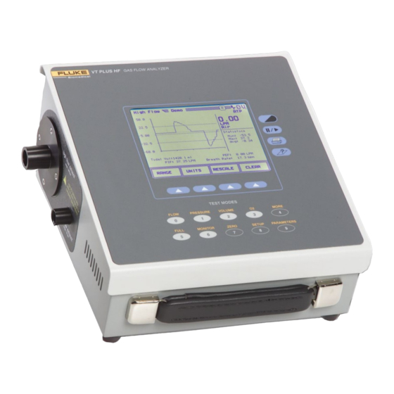
Introduction Introduction The VT Plus HF Gas Flow Analyzer, referred to hereafter as the Analyzer, is a general- purpose, gas flow analyzer with special modes for testing mechanical patient ventilators. The Analyzer measures bidirectional flow in both high and low ranges, as well as high- and low-pressure ranges. -
Page 16: General Safety Considerations
Œ Conforms to UL Std 3101-1; certified to Can/USA Std C22.2 No. 1010.1 Conforms to European Union directives Do not dispose of this product as unsorted municipal waste. Go to Fluke’s website for recycling information. Warnings and Cautions A Warning identifies hazardous conditions and actions that could cause bodily harm or death. -
Page 17: Instrument Familiarity
Introduction and Specifications Instrument Familiarity W Caution To avoid damage to the Analyzer or adverse affects on its performance, follow these guidelines: • Do not expose the system to temperature extremes. Ambient temperatures should remain between 10 °C and 40 °C. System performance may be adversely affected if temperatures fluctuate above or below this range. -
Page 18: Front Panel
VT Plus HF Operators Manual Front Panel The components of the front panel are listed in Table 1-2. See Front Panel Details for detailed descriptions of front panel components. Table 1-2. Front Panel Components Label Description LCD Display with CFL backlight... -
Page 19: Rear Panel
Introduction and Specifications Instrument Familiarity fec121.eps Figure 1-2. Rear and Left Analyzer Panels Rear Panel The components of the back panel are listed in Table 1-4. Table 1-4. Back Panel Components Label Description RS232 Serial Port Parallel Printer Port Power Switch Power Cord Input Oxygen Sensor Access Left Panel... -
Page 20: Front Panel Details
VT Plus HF Operators Manual Front Panel Details Figure 1-3 shows details of the Analyzer front panel, and Table 1-6 describes the various keys, their icons, and functions. VT PLUS HF GAS FLOW ANALYZER TEST MODES fec011.eps Figure 1-3. Analyzer Front Panel Table 1-6. - Page 21 Introduction and Specifications Instrument Familiarity Table 1-6. Functions (cont.) Icon Name Function Print This key prints the current data to the printer. The mode and format of the printout is set using the printer options function selected under the setup menu. Help This key displays help for any screen.
-
Page 22: Specifications
VT Plus HF Operators Manual Table 1-6. Functions (cont.) Icon Name Function ZERO/7 Key This key initiates the zero function in the Analyzer. All of the pressure and differential pressure (flow) sensors in the Analyzer must be periodically zeroed or calibrated to a zero reference. -
Page 23: Performance Specifications
Introduction and Specifications Specifications Power Consumption ....... <132 VA Fuse Rating ........0.5 A, Slo-Blo Performance Specifications Low-Pressure Port Maximum Applied Pressure..... 60 psi Operating Pressure ......(Differential) ±500 mmHg (±10 psi) (Common-mode) 30 psi Span Accuracy ........ ±0.80 % of reading or ±1.5 mmHg, whichever is greater Frequency Response ...... -
Page 24: Breath Parameter Accuracy Specifications
VT Plus HF Operators Manual Frequency Response..... >25 Hz or t10-90 <40 ms, whichever is greater Sample Rate........100 Hz Dynamic Resistance....... <2.00 cmH O @ 60 lpm Low-flow Dropout......25 lpm Breath Detect Threshold....(user settable) 2.0 lpm Volume Range........ - Page 25 Introduction and Specifications Specifications Table 1-7. Breath Parameter Accuracy Specifications Parameter Resolution Range Accuracy Inspiratory and 0.1 ml As specified in As specified in Expiratory Tidal Volume high/low-flow spec high/low-flow spec Minute Volume 0.001 lpm 0-60 l Breath Rate 0.1 bpm 0.5 –...
-
Page 26: Accessories
VT Plus HF Operators Manual Accessories Table 1-8 lists standard accessories provided with the Analyzer. Table 1-9 lists optional accessories. Table 1-8. Standard Accessories Item Part Number Operators manual 2137275 VT for Windows PC software 2392054 Standard bi-directional RS232 serial cable... - Page 27 Introduction and Specifications Accessories Table 1-9. Optional Accessories Item Part Number Soft vinyl carrying case 2222822 Hard-sided protective carrying case 2248587 Soft-sided carrying case for ACCU-LUNG 2397628 Graphics Printer 110 V Citizen IDP3110 2248762 220 V Citizen IDP3110 2719653 D25 male to Centronics parallel cable 2238072 ACCU-LUNG Lung Simulator with Soft-sided 2387318...
- Page 28 VT Plus HF Operators Manual 1-16...
- Page 29 Chapter 2 Connection and Setup Title Page Connecting the Analyzer ................... 2-3 Pneumatic Connections ................. 2-3 High Flow (Inlet and Exhaust) ..............2-3 Low Flow (Inlet and Exhaust)..............2-3 High Pressure (+ and -) ................2-3 Low Pressure (+ and -)................2-4 Test System Setup ..................
- Page 30 VT Plus HF Operators Manual Keypad ...................... 2-17 Errors......................2-18 Restore Defaults .................... 2-18 Utilities ......................2-20 Oxygen Sensor Calibration................2-20 System Diagnostics ..................2-21 Linearization....................2-21 Unlock Calibration ..................2-22 Information ......................2-22...
-
Page 31: Connection And Setup
Connection and Setup Connecting the Analyzer Connecting the Analyzer The Analyzer can be connected to a ventilator and a test load in either a bidirectional or unidirectional flow configuration. Pneumatic Connections The following is a description of various pneumatic connections on the Analyzer. High Flow (Inlet and Exhaust) The outer diameter of the high flow ports is a standard 22 mm fitting to allow connection using patient hoses. -
Page 32: Low Pressure (+ And -)
VT Plus HF Operators Manual Low Pressure (+ and -) The low-pressure ports connect using standard luer fittings. Note that only the + side can be used to measure fluid pressure. W Caution To avoid damage to the Analyzer or adverse affects on its performance, follow these guidelines: •... -
Page 33: Unidirectional Flow Mode
1. Connect the inspiratory hose to the flow port on the right of the Analyzer. 2. Connect the flow exhaust port on the left to the test lung using standard breathing hoses. Inlet Outlet Inspiratory Hose VT PLUS HF TEST Ventilator LUNG Expiratory Hose fec008.eps Figure 2-2. -
Page 34: Printer Cable Attachment
Printer Cable Attachment The printer uses a D25 male to Centronics parallel cable for parallel printing. This cable is available from Fluke (part #2238072) or from most electronic supply outlets. To attach the parallel cable: 1. Connect the 36-pin end for the Centronics type parallel cable to the printer’s parallel input connector. -
Page 35: Using The Setup Screen
Connection and Setup Using the Setup Screen Using the Setup Screen To use the Setup screen: 1. Press the SETUP/8 key. The Setup screen displays: fec027.bmp The options are: Settings – a menu for choosing options that affect flow and measurement on the •... -
Page 36: Gas Settings
VT Plus HF Operators Manual Note The option displayed when exiting the settings screen is saved and used for future measurements. The following is a description of each setting. Gas Settings This setting tells the Analyzer what type of gas is flowing through the high- and low-flow ports. -
Page 37: Gas Temperature
Connection and Setup Setting Testing Parameters 1. From the Gas Settings menu, highlight Gas Type. 2. Press the MODIFY soft key until the desired value displays. 3. Press the BACK soft key to return to the Settings menu. Gas Temperature This setting is the temperature of the gas flowing through the high- or low-flow port. -
Page 38: Correction Mode
VT Plus HF Operators Manual 3. Input the desired value from the keypad. 4. Press the ENTER soft key to save the change or the ESCAPE soft key to cancel the change. 5. Press the BACK soft key to return to the Settings menu. -
Page 39: Breath Detection
Connection and Setup Setting Testing Parameters Note The Analyzer accepts barometric pressure values between 0 and 999 mmHg. No decimal values or fractions are allowed. 4. Press the ENTER soft key to save the change or the ESCAPE soft key to cancel the change. -
Page 40: Inspiratory/Expiratory Tidal Volumes
VT Plus HF Operators Manual 4. Press the ENTER soft key to save the change or the ESCAPE soft key to cancel the change. 5. Press the BACK soft key to return to the Settings menu. Inspiratory/Expiratory Tidal Volumes The Analyzer measures tidal volume when performing ventilator measurements. This option allows the user to choose between the expiratory or the inspiratory tidal volume. -
Page 41: Setting Analyzer Operating Parameters
Connection and Setup Setting Analyzer Operating Parameters Setting Analyzer Operating Parameters To adjust system information: 1. From the Setup screen, highlight System and press the ENTER soft key. The System menu displays: fec032.bmp 2. Change settings to pre-selected options or to numeric values by highlighting the option and pressing the MODIFY soft key. -
Page 42: Date
VT Plus HF Operators Manual 4. Press the ENTER soft key to save the change or the ESCAPE soft key to cancel the change. 5. Press the BACK soft key to return to the Settings menu. Note For hour and minute values less than 10, enter a leading zero. For example, if the time is 9:05, enter 0905. -
Page 43: Filtering
Connection and Setup Setting Analyzer Operating Parameters 3. Press the ENTER soft key to save the change or the ESCAPE soft key to cancel the change. 4. Press the BACK soft key to return to the Settings menu. Filtering This setting is used to adjust the transition of signals on the flow meters. The filter has four levels: Soft, Medium, Hard, and None. -
Page 44: Printer Options
VT Plus HF Operators Manual To select the serial mode options follow these steps: 1. Highlight Serial Mode. 2. Press the MODIFY soft key to toggle to the desired value. 3. Press the ENTER soft key to save the change or the ESCAPE soft key to cancel the change. -
Page 45: Graphics
Connection and Setup Setting Analyzer Operating Parameters Graphics To choose the format of reports shown: 1. Highlight Graphics and press the MODIFY soft key to toggle between Graphics or Text Only. 2. Press the ENTER soft key to save the change or the ESCAPE soft key to cancel the change. -
Page 46: Errors
VT Plus HF Operators Manual Errors When an error is made, the Analyzer signals it with a beep. This option adjusts the sound level of that beep. To adjust the sound level of errors: 1. Highlight Errors and press the MODIFY soft key to toggle between Low , High, or Off. - Page 47 Connection and Setup Setting Analyzer Operating Parameters Table 2-4. Factory Defaults (cont.) Settings (cont.) 33 °C Rel. Humidity Correction Mode Baro Press Units mmHg Barometric Pressure Actual ambient pressure Breath Detect Bidirectional LF BD Threshold 0.50 lpm HF BD Threshold 2.00 lpm Bi-Dir Tidal Vol Inspiratory...
-
Page 48: Utilities
VT Plus HF Operators Manual Utilities Note These settings are required by service technicians in servicing the Analyzer. To access the utility functions: 1. From the Setup screen, highlight Utilities and press the ENTER soft key. The Utilities menu displays: fec035.bmp... -
Page 49: System Diagnostics
Connection and Setup Utilities 4. Press the ZERO soft key. 5. Press OK to start 21 % O calibration. Allow the full 2-minute period. Do not press SKIP. 6. Verify that the O2 reading is 20.9 ±0.1 %. 7. Press the CAL soft key. 8. -
Page 50: Unlock Calibration
VT Plus HF Operators Manual Unlock Calibration This function is for technical service personnel to use while repairing the Analyzer. When the Unlock Calibration is highlighted and the ENTER soft key is pressed, calibration is unlocked, and the display returns to the Utilities menu. - Page 51 Chapter 3 Operation Title Page Measured Signals....................3-3 High Flow...................... 3-3 Low Flow ...................... 3-3 Airway Pressure..................... 3-3 Low Pressure ....................3-3 Barometric Pressure..................3-4 High-Pressure Measurement................3-4 Oxygen Concentration................... 3-4 Calculated Breath Parameters................ 3-4 Screen Objects ....................3-6 Title Bar......................3-7 Data Plots ......................
- Page 52 VT Plus HF Operators Manual...
-
Page 53: Operation
Operation Measured Signals Measured Signals The Analyzer measures the following signals: High flow • Low flow • Airway pressure • Low pressure • Barometric pressure • High Pressure • Oxygen concentration • Calculated breath parameters • High Flow The Analyzer has a high-flow (±300 LPM), bi-directional flow measurement. Flow measurements can be either static flows (no breath variations) or ventilator waveforms (i.e., both an expiratory and an inspiratory phase). -
Page 54: Barometric Pressure
VT Plus HF Operators Manual Barometric Pressure A barometric pressure measurement is provided by the Analyzer. The barometer can read absolute pressures from 8 to 18 PSIA. The barometer is also used in the automatic ATP, BTPS, and STPD conversions for flow and volume measurements. The barometric pressure signal can be fine tuned using the procedure described in System Setup. - Page 55 Operation Measured Signals Table 3-1. Parameters Calculated by the Analyzer Parameter Abbreviation How Calculated Inspiratory Time In Time Time of the inspiratory period including the inspiratory hold time Expiratory Time Ex Time Time of the expiratory period including the expiratory hold time Inspiratory Hold Time In Hold Time of the End Inspiratory State...
-
Page 56: Screen Objects
VT Plus HF Operators Manual Screen Objects Classes of information shown on the Analyzer display are a title bar, various breath detection icons, statistics, data plots, instantaneous numeric value of plotted data, and selected breath parameters, as shown in Figure 3-1 and listed in Table 3-2. -
Page 57: Title Bar
Operation Screen Objects Title Bar Each screen includes a title bar that shows the screen or mode name on the left. A number indicating the screen number is shown in a small box on the right of the title bar: fec039.bmp Indicates the screen number Data Plots... -
Page 58: Breath Detection Icons
VT Plus HF Operators Manual Breath Detection Icons The breath-detection icon is located on the right side of the title bar. Various icons and their meanings are listed in Table 3-3. Table 3-3. Breath Detection Icons Icon Meaning A large number 0 to the right of the title bar indicates that automatic sensor- zeroing mode has been selected. -
Page 59: Instantaneous Numeric Data
Operation Screen Objects Instantaneous Numeric Data The digital value of the plotted signal is displayed to the right of each plot: fec046.bmp This value is updated approximately twice a second. This value is the average of the signal over the previous 500 milliseconds. The Analyzer allows the user to select the desired units for each of the measured signals. -
Page 60: Selecting Breath Parameters
VT Plus HF Operators Manual Selecting Breath Parameters The Analyzer calculates 17 breath parameters for every breath: fec048.bmp The user can select up to four of these parameters to be displayed with each of the screens. To select parameters for display on a specific screen: 1. -
Page 61: Flow Screens
Operation Flow Screens Flow Screens There are two types of flow screen, high-flow and low-flow, based on which Analyzer flow port is used. High-Flow Screen The High-Flow screen displays the signal and statistics for flow in the high-flow port of the Analyzer. -
Page 62: Low-Flow Screen
VT Plus HF Operators Manual Low-Flow Screen The Low-Flow screen displays the signal and statistics for the flow in the low-flow port of the Analyzer. fec050.bmp Range Press the RANGE soft key to change from a high-flow screen to a low- flow screen or back again. -
Page 63: Pressure Screens
Operation Pressure Screens Pressure Screens There are two types of pressure screen, high-pressure and low-pressure, based on which Analyzer pressure port is used. High-Pressure Screen The High-Pressure screen displays the signal and statistics for the pressure signal from the high-pressure ports of the Analyzer. fec051.bmp Range Press the RANGE soft key to change between low pressure, airway... -
Page 64: Low Pressure Screen
VT Plus HF Operators Manual Low Pressure Screen The Low-Pressure screen displays the signal and statistics for the pressure signal from the low-pressure ports of the Analyzer. fec052.bmp Range Press the RANGE soft key to change between low pressure, airway pressure, and high-pressure screens. -
Page 65: Airway Pressure Screen
Operation Pressure Screens Airway Pressure Screen The Airway Pressure screen displays the signal and statistics for whichever range is currently selected in either the high- or low-flow ports of the Analyzer. This screen measures the pressure in a ventilated test lung. The airway pressure displayed is that for the selected high- or low-flow port. -
Page 66: Volume Screen
VT Plus HF Operators Manual Volume Screen The Volume screen displays the signal and statistics for the volume signal. fec053.bmp The volume signal is the integral of the flow signal measured in either the high or low flow ports. The flow port that is integrated is selected by selecting the high- or low-flow range from within the flow screen. -
Page 67: Oxygen Screen
Operation Oxygen Screen Oxygen Screen The Oxygen screen displays the signal and statistics for the oxygen sensor. fec054.bmp The Analyzer measures oxygen in the high-flow port. If oxygen in the low-flow port is to be measured, the flow of gas must be passed through the high-flow port also to measure oxygen. -
Page 68: Full Breath Parameters Test Screen
VT Plus HF Operators Manual Full Breath Parameters Test Screen The Full Test screen displays all of the breath parameters calculated by the Analyzer. fec055.bmp Note Breath detection must be enabled for breath parameters to be calculated. See System Setup for instructions on enabling breath detection. -
Page 69: Monitor Screen
Operation Monitor Screen Monitor Screen The Monitor screen shows three signals and their corresponding values. fec056.bmp Alternatively, the lower signal can be replaced by a set of four breath parameters. The user can select which signals are displayed on the monitor screen. Select Press the SELECT soft key to change the position of the plot that can be altered using the ASSIGN and UNITS soft keys. -
Page 70: Units Of Measure
VT Plus HF Operators Manual Units of Measure The Analyzer has the capability to display the above signals and parameters in the following units of measure shown in Table 3-4 . Table 3-4. Available Units of Measure Unit Description Flow... -
Page 71: Special Functions
Operation Special Functions The Analyzer has conversion factors for gas, volume, and flow measurements, as shown in Table 3-5. Table 3-5. Available Conversion Factors Conversion Factor Description Conversion for gas flow and volume to ambient temperature and pressure STPD0 Conversion for gas flow and volume to a standard temperature of 0 °C and a standard barometric pressure of 760 mmHg STPD21 Conversion for gas flow and volume to a standard temperature... - Page 72 VT Plus HF Operators Manual 1. Use the soft keys to highlight Test Parameter. 2. Press the MODIFY soft key until the desired breath parameter displays. The most recent measurement of the selected parameter is displayed as the Current Value.
- Page 73 Operation Special Functions TREND TEST REPORT 6/13/2000 10:45 VT PLUS HF S/N: 4294967295 Control #: __________________ S/N: __________________ Tech: __________________ Incident Report Test Parameter: Minute Vol Elapsed Time: 0:00:05 Current Value: 40.333 L Starting Value: 28.686 L % Difference: 41 %...
-
Page 74: Leak Test
VT Plus HF Operators Manual Leak Test The Analyzer allows the user to test the leak rate of a sealed vessel or test lung. A Leak test can be done using the high pressure, low pressure, or airway pressure signals to measure the leak rate of a sealed vessel or test lung. - Page 75 Operation Special Functions 7. Use the keypad to enter the duration of the Leak test in hours, minutes, and seconds. Six digits must be entered to set the test time. The time is entered in the following format: HHMMSS (HH is the hours (0-99), MM is the minutes (0-59) and SS is the seconds (0-59).
- Page 76 VT Plus HF Operators Manual A sample Leak Test Report is shown below. Fluke Biomedical Corporation 1/2/2000 3:05 VT PLUS HF S/N: 166752 Control #: __________________ S/N: __________________ Tech: __________________ Leak Test: Low Press 0.02 Kpa Compliance: 0.00 ml/cmH2O Start Press: 0.00 Kpa...
-
Page 77: Stacked Volume Test
Operation Special Functions Stacked Volume Test The Stacked Volume test measures the volume of multiple breaths to determine the accuracy of the ventilator in accumulating volume. To access the Stacked Volume test: 1. Press the MORE/4 key. 2. Use the soft keys to highlight Stacked Volume Test. -
Page 78: Rt200 Emulation Mode
VT Plus HF Operators Manual RT200 Emulation Mode The Analyzer can emulate RT200 serial port communications. This mode is used for some ventilator automated test procedures. To set the RT200 emulation mode: 1. From the Setup screen, select System. 2. Use the soft keys to highlight Serial Mode. - Page 79 Operation Special Functions the command string. When a command is received, it is displayed in the box named Received String. Refer to Serial Interface for the RT200 Calibration Analyzer System – Operation Manual from Allied Healthcare Products, Inc. for the format of serial commands.
- Page 80 VT Plus HF Operators Manual The soft keys for the RT200 screen are: SETUP RS232 – displays a screen for setting the baud rate, number of data bits, and the terminator character: fec071.bmp These settings affect only the RT200 emulation mode and not the other serial communication modes.
-
Page 81: Assist Test
Operation Special Functions Assist Test The Assist test determines the sensitivity of the ventilator in patient assist mode and helps to calibrate the full range of assist pressures under which the ventilator can operate. During an assisted breath, the airway pressure drops during the inspiration due to the spontaneous breath. -
Page 82: High Frequency Oscillator Mode
VT Plus HF Operators Manual 4. Ensure that the ventilator is delivering breaths in a steady manner. 5. Gently lift the back of the test lung top plate during the expiratory hold period in a smooth, steady pull to create negative pressure. - Page 83 Operation Special Functions To run the HFO test: 1. Press the START or AUTO soft key to begin the test. The START soft key runs the test once, while the AUTO soft key starts the HFO test in automatic mode. In automatic mode the HFO test is run every 15 seconds.
- Page 84 VT Plus HF Operators Manual 3-34...
- Page 85 Chapter 4 Remote Operation Title Page Getting Started ....................4-3 System Requirements ..................4-3 Connecting to the Analyzer ................4-3 Installing the Software................... 4-3 Starting the Software ..................4-4 Overview of VT for Windows PC Software............4-5 Menu Bar ......................4-6 Toolbar.......................
- Page 86 VT Plus HF Operators Manual Zeroing....................... 4-30 Manual Zeroing ..................... 4-30 Automatic Zeroing..................4-30 Other Setup Functions ..................4-31 Breath Detect ....................4-31 Breath Detect Threshold................4-31 Gas Settings ....................4-31 Barometric Pressure..................4-34...
-
Page 87: Remote Operation
Remote Operation Getting Started Getting Started The Analyzer can be run by the VT for Windows PC software from a PC that meets the minimum requirements listed below. The two must be connected properly, and the VT for Windows PC software installed as described. Then, the PC must establish communications with the Analyzer. -
Page 88: Starting The Software
VT Plus HF Operators Manual Starting the Software The software application is ready to start when the software has been installed and the Analyzer connected. The first time the software is used, the application attempts to establish communications with the Analyzer and displays the following: fec109.bmp... -
Page 89: Overview Of Vt For Windows Pc Software
Remote Operation Overview of VT for Windows PC Software Finally, if the communication port for the Analyzer must be manually set or changed, start VT for Windows PC software and select Communications > Comm Port from the pull down menu. Select the appropriate communication port. Communications are established when the software displays waveforms and the displayed values for flow and pressure are changing. -
Page 90: Menu Bar
VT Plus HF Operators Manual Table 4-1. Elements of the VT for Windows Interface Label Element Menu Tool Bar Statistics Area Plot Area Screen Tabs Status Bar Selected Flow Port Correction Mode Zeroing Mode Selected File \ System Messages Review and test screens are accessed through the Screen tabs near the bottom of the screen;... - Page 91 Remote Operation Menu Bar Table 4-2. Menu Bar Options Option Description File This menu gives access to the file handling, and printing functions of this software. For a complete description see the Data and File Handling section in this chapter. Communications The communications menu allows selection of the communications port and the serial data mode.
-
Page 92: Toolbar
VT Plus HF Operators Manual Toolbar The toolbar is provided for both convenience and speed. It provides a quick and easy way to call often used functions. Figure 4-3 shows the toolbar, while Table 4-4 lists the toolbar buttons, along with their functions and descriptions. -
Page 93: Main Screens And Tests
Remote Operation Main Screens and Tests Main Screens and Tests VT for Windows has seven main screens that are accessed through the Screen tabs; these are listed below: Monitor screen • Single Plot screen • Loop Plots screen • Full Test screen •... -
Page 94: Single Plot Screen
VT Plus HF Operators Manual Single Plot Screen The Single Plot screen, shown in Figure 4-5, allows observation of one of the signals. fec087.bmp Figure 4-5. Single Plot Screen The plot can be configured to display any of the signals, (flow, volume, airway pressure, low pressure, high pressure, and oxygen). -
Page 95: Loop Screen
Remote Operation Main Screens and Tests Loop Screen The Loop, or Loop Plots, screen, shown in Figure 4-6, displays plots of Flow vs. Volume and Volume vs. Airway Pressure. fec088.bmp Figure 4-6. Loop Screen These plots can be independently re-scaled either automatically or manually. Controls located on the right-hand side of the screen are used to control the appearance of the loop plots: Clear Volume –... -
Page 96: Full Test Screen
VT Plus HF Operators Manual Full Test Screen The Full-Test screen, shown in Figure 4-7, displays the calculated parameters for the last breath. fec089.bmp Figure 4-7. Full Test Screen These parameters are only updated when a new breath occurs. A ***** value means that value is invalid or could not be calculated. - Page 97 Remote Operation Main Screens and Tests Setting Trend Test Parameters The Trend test setup screen, shown in Figure 4-8, allows the user to choose the parameter to run the test on and to choose the percent limit for the test. fec090.bmp Figure 4-8.
- Page 98 VT Plus HF Operators Manual Running the Trend Test To run the Trend test: 1. Click the START button. The screen changes, as shown in Figure 4-9. fec091.bmp Figure 4-9. Trend Test Screen: Testing Underway While a test is running, screens cannot be changed until the STOP button that appears at the bottom of the screen has been clicked.
- Page 99 Remote Operation Main Screens and Tests Ending the Trend Test: To end the Trend test: 1. Click the STOP button. When the trend test is stopped, the final values are displayed, as shown in Figure 4-10: fec092.bmp Figure 4-10. Trend Test Screen: Final Values Displayed 2.
-
Page 100: Leak-Test
VT Plus HF Operators Manual Leak-Test The Leak test is used for measuring the leak rate of a sealed vessel or test lung over a period of time. Setting Leak Test Parameters The Leak test setup screen, shown in Figure 4-11, allows the user to choose the desired pressure channel on which to run the test. - Page 101 Remote Operation Main Screens and Tests fec094.bmp Figure 4-12. Leak Test Screen: Testing Underway Screens cannot be changed until the test being run has ended. The Leak test plots the chosen pressure channel (airway, low, or high pressure) over the chosen length of time.
-
Page 102: Stacked Volume Test Screen
VT Plus HF Operators Manual Ending the Leak Test To end the Leak test: 1. Either click the STOP button or let the Leak test end by the time running out. When the Leak test is over a report is prepared showing the final values for the calculated parameters. - Page 103 Remote Operation Main Screens and Tests Running the Stacked Volume Test To run the stacked volume test: 1. Click the START button to begin testing. The screen changes, as shown in Figure 4-14: fec096.bmp Figure 4-14. Stacked Volume Screen: Testing Underway When the stacked volume test begins, the Analyzer switches into Inspiratory Only breath-detect mode.
-
Page 104: Serial Communications
VT Plus HF Operators Manual Ending the Stacked Volume Test To end the Stacked Volume test: 1. Either click the STOP button or let the Stacked Volume test end following the number of requested breaths. 2. Click the Print button to print a final report for the Stacked Volume test. -
Page 105: Data And File Handling
Remote Operation Data and File Handling Data and File Handling VT for Windows files handle three kinds of data, as described in Table 4-5. Table 4-5. Data Types Data Type Descriptions Signals Raw flow, pressure, and volume time-series waveforms Parameters Breath-by-breath ventilator parameters calculated by the Analyzer device Events Information placed into the data files by the user... -
Page 106: Opening And Closing Data Files
VT Plus HF Operators Manual The user initiates TIME STAMP and ANNOTATE events by pressing a button provided for each. Each event is described below. A file control interface is provided to aid in data collection and data playback. Automatic events are placed in the file to assist in the rewind and forward functions of the data file playback. -
Page 107: File Control Interface
Remote Operation Data and File Handling File Control Interface The File Control interface, shown in Figure , is a sub-screen used for recording, annotating, and playback of data files. It is accessed by clicking the File Control button on the toolbar or by selecting File Controls from the File menu. fec098.bmp Figure 4-16. -
Page 108: Playback Controls
VT Plus HF Operators Manual Playback Controls Playback controls are provided to facilitate data review and recording. Table 4-7 lists the controls, their icons, and a description of each. Table 4-7. Playback Controls Icon Control Description RECORD Initiates writing data to the open data file; a TIME STAMP event marker is placed in the data file indicating the beginning of recording. -
Page 109: Event Markers
Remote Operation Data and File Handling Event Markers Two buttons allow placement of event markers into a file, assisting the user during data collection: Annotate and Time. During file recording, these events appear in the Event panel. Pressing the Time button during recording places a time stamp in the data file. A •... -
Page 110: File Information Panel
VT Plus HF Operators Manual File Information Panel The File Information panel is shown in Figure 4-17. fec108.bmp Figure 4-17. File Information Panel The first line in the File Information panel contains the open file name. The next line is the time that the file was first created. -
Page 111: Report Printing
Operating System Loading VT for Windows can be used as a utility to load new versions of the Analyzer operating system software into the flash memory of the Analyzer. Contact the Fluke Biomedical Service Center for Analyzer software updates. Note... -
Page 112: Plots
VT Plus HF Operators Manual Plots Automatically Re-scaling Plots By default, VT for Windows attempts to re-scale plots so that the entire plot is visible. When a re-scale occurs, the high- and low-ranges on the plots are determined by the min and max statistics for the signal shown on the plot. -
Page 113: Signal Selection
Remote Operation Plots fec112.bmp Type the desired the range and click OK. Right-click the plot to re-scale. Select Manual Scale; the above dialog box appears. • Type the preferred range and click OK. Signal Selection Three plots on the Monitor screen and the plot on the single plot screen can be set up to display any of the signals flow, volume, airway pressure, low pressure, high pressure, or oxygen. -
Page 114: Zeroing
VT Plus HF Operators Manual Zeroing The Analyzer can be zeroed either automatically or manually. Zeroing corrects the flow and pressure sensors for offset to get a more accurate reading. To switch the Analyzer between automatic and manual zeroing: 1. From the Setup menu, select the Zeroing menu. The current zeroing mode has a check next to its name. -
Page 115: Other Setup Functions
Remote Operation Other Setup Functions Other Setup Functions VT for Windows allows selection of settings in the Setup menu. Breath Detect The Analyzer has a built-in breath detection algorithm. The algorithm determines the breath phase (inspiration, expiration, inspiratory pause, single phase bi-directional) This algorithm is designed to reject signal noise and other artifact when determining the phases of a breath. - Page 116 VT Plus HF Operators Manual fec116.bmp 2. Enter changes as desired. 3. If necessary, click the Advanced button. The Gas Settings Date Entry dialog box displays. fec117.bmp 4. Make appropriate entries to adjust temperature, viscosity, molecular weight, and relative humidity for both inhaled and exhaled gases. Ambient temperature can be...
- Page 117 Remote Operation Other Setup Functions fec118.bmp The gas calculator allows calculation of the viscosity and molecular weight of a gas mixture. One gas serves as a balance gas. This means that the percentage of this gas is automatically adjusted to insure that the total percentage of gases totals 100 %. 6.
-
Page 118: Barometric Pressure
VT Plus HF Operators Manual 9. Click OK to accept all gas settings changes. Barometric Pressure The Analyzer automatically calculates the barometric pressure to within 2 % of full scale. To give greater accuracy, the Analyzer allows the user to calibrate the barometric pressure offset by entering the local barometric pressure into the system. -
Page 119: Maintenance, Service, And Calibration
Chapter 5 Maintenance, Service, and Calibration Title Page Maintenance....................... 5-3 Avoiding Damage..................5-3 Cleaning......................5-3 Oxygen Sensor Replacement ................5-3 Fuse Replacement ....................5-4 Service and Calibration..................5-5... - Page 120 VT Plus HF Operators Manual...
-
Page 121: Maintenance
3. Disconnect the in-line electrical connector on the sensor wire. 4. Un-screw the old sensor and remove it. 5. Screw in the new sensor (Fluke part #2138514). 6. Re-connect the sensor wire. 7. Replace the oxygen sensor door. -
Page 122: Fuse Replacement
The fuse block assembly is attached to the back of the cover. 3. Pull out the fuse block assembly and carefully lift the old fuses from the fuse slots. 4. Replace the fuses (two 0.5 A Slo-Blo fuses, Fluke part #46026). XW Warning To avoid possible fire, electrical shock, or personal injury, use only the recommended fuse. -
Page 123: Service And Calibration
The Analyzer should be calibrated annually to maintain accurate measurements. If the Analyzer fails to operate successfully or if it needs calibration, return it to the Fluke Biomedical Service Center, as indicated under Warranty and Product Support. As part of this service, hardware and software updates are automatically installed. - Page 124 Fluke Biomedical Service. 2. Enclose your return address and Return Authorization Number. 3. Insure the unit for full retail value and ship to the nearest Fluke Biomedical Service Center.
-
Page 125: Appendices
Appendices Appendix Title Page Gas Analyzer Tutorial ..................A-1 Error Messages....................B-1 Troubleshooting ....................C-1... - Page 126 VT Plus HF Operators Manual...
- Page 127 Appendix A Gas Analyzer Tutorial The Analyzer measures the basic signals of pressure, flow, and oxygen. From these basic signals, other parameters are computed. Volume is obtained from the integration, or summation, of the flow signal over a period of time. Pressure Measurements The Analyzer provides several pressure measurement capabilities.
- Page 128 VT Plus HF Operators Manual If fluid enters into the pressure measurements connections of the Analyzer, it is important to evacuate the fluid before storage and before any pressure measurements are made. The fluid can be evacuated by connecting a 100 cc syringe directly to the pressure measurement connection and then pulling back the syringe to create a vacuum.
- Page 129 Appendices Gas Analyzer Tutorial Oxygen Measurements Oxygen measurement is performed using a galvanic oxygen cell on the high-flow port near the exhaust. The Analyzer interprets the measurement from the oxygen sensor as a partial pressure of the total pressure in the high-flow circuit. The total pressure is the airway pressure plus the barometric pressure.
- Page 130 VT Plus HF Operators Manual Note Never apply humidified gases to the Analyzer flow sensors. Condensation on the flow sensors causes errors in the flow readings until it is dried off. Balance Gas Settings The gas settings allow for gas combinations with oxygen. For example, the Analyzer can be set to use Helium balance Oxygen.
- Page 131 Appendices Gas Analyzer Tutorial In the manual zero mode, if the user presses the ZERO/7 key when the Analyzer is at the Flow screen, a message appears, indicating that the flow must be removed from the currently selected flow port. The user must remove the flow so that a correct zero reading can occur.
- Page 132 VT Plus HF Operators Manual Inspiratory Hose TEST Ventilator Analyzer LUNG Inlet Outlet Expiratory Hose fec002.eps Figure A-1. Circuit Connection for the Analyzer in Bi-directional Mode Note When using the Analyzer with a ventilator and a test lung, the bidirectional breath detect mode is preferred.
- Page 133 Appendix B Error Messages Table B-1 lists error messages, their descriptions, and corrective actions. Table B-1. Error Messages Error Message Description Corrective Action Flow Out of Range Differential pressure for the flow Ensure that flow is within the measurement causes a specified range of the Analyzer.
- Page 134 VT Plus HF Operators Manual Table B-1. Error Messages (cont.) Error Message Description Corrective Action Airway Pressure Out of Range Airway-pressure measurement Ensure that pressure is within causes a measurement greater the specified range of the than the maximum (or less than Analyzer.
- Page 135 Appendices Error Messages Table B-1. Error Messages (cont.) Error Message Description Corrective Action Zero Time Out A flow zero isn’t complete after Attempt to zero again. Ensure 150 attempts. that no flow or pressure is on either the high- or low-flow ports. If message does not go away after several attempts (with no flow or pressure applied), call...
- Page 136 VT Plus HF Operators Manual Table B-1. Error Messages (cont.) Error Message Description Corrective Action Printer Busy The printer’s busy line is set. Ensure that the printer is selected (refer to printer's user manual). Ensure the correct printer type is selected. Refer to...
- Page 137 Appendix C Troubleshooting Table C-1 lists problems, possible causes, and corrective actions. Table C-1. Troubleshooting Problem Possible Cause Corrective Action Analyzer does not turn on – No power Screen contrast not Plug unit into an AC mains outlet Screen is dark set Blown fuse using the supplied power cord.
- Page 138 VT Plus HF Operators Manual Table C-1. Troubleshooting (cont.) Problem Possible Cause Corrective Action Out of Range messages appear Measured signals out of Ensure that all pressures and specified range flow rates are within the Analyzer specified limits. Units are not set to those used for the range specifications.
- Page 139 Appendices Troubleshooting Table C-1. Troubleshooting (cont.) Problem Possible Cause Corrective Action BTPS or STPD correction Corrections for BTPS and STPD method on the Analyzer is may vary among different different that the method used by ventilator manufactures. The the ventilator manufacturer. biggest difference is in the water vapor volume correction.
- Page 140 VT Plus HF Operators Manual Table C-1. Troubleshooting (cont.) Problem Possible Cause Corrective Action Flow or pressure measurement Baseline drift of pressure Zero the affected signal by using is not equal to zero when zero transducer the zero key while the affected flow or pressure is applied.
- Page 141 Appendices Troubleshooting Table C-1. Troubleshooting (cont.) Problem Possible Cause Corrective Action Analyzer does not print. Wrong printer type selected Select correct printer type on the Analyzer. Printer not set up for selected Review printer's user manual to printer language determine how to set up printer to work with the selected Analyzer printer mode Printer not connected...
- Page 142 VT Plus HF Operators Manual...
Need help?
Do you have a question about the VT Plus HF and is the answer not in the manual?
Questions and answers