Advertisement
Quick Links
Advertisement

Related Manuals for Fluke PRUFTECHNIK VIB 6.172


Summary of Contents for Fluke PRUFTECHNIK VIB 6.172
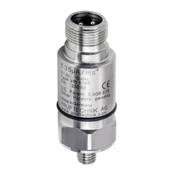
- Page 1 Accelerometer (100mV/g) VIB 6.172, VIB 6.210 Installation and Operation...
- Page 2 Mounting Accelerometers of the VIB 6.172 and VIB 6.210 series are used for the measurement of absolute The frequency response and dynamic range of an casing vibrations on machinery with rotating com- accelerometer can be greatly influenced by the ponents. Due to the very low limit frequency, the installation.
- Page 3 • Clean the area around the mounting hole and Roughen the mounting surface with a file (filing a roughen it with abrasive paper (type 220). few grooves in a diamond pattern provides great- er adhesion.) • Clean the contact surfaces of the accelerometer / adapter and of the machine with solvent.
- Page 4 Technical Data PARAMETER VIB 6.172 VIB 6.210 Signaling system Voltage output according to IEPE standard Transmission factor ± 4% 100 mV/g (ref.: 159 Hz; 25 °C) Frequency range ± 3dB 0.1 Hz ... 10 kHz Resonant frequency 17 kHz; > 10 dB damped 15 kHz;...
- Page 5 Installation height VIB 5.740-X VIB 5.741-X VIB 3.575-10 VIB 3.575-20 T r i Dimensions in mm VIB 6.172 VIB 6.210 Pin allocation, accelerometer VIB 6.172 VIB 6.210 Signal (+) GND (-) 1 : Signal (+) 2 : nc 3 : GND (-) 4 : nc...
- Page 6 Electrical connection Lay the cable Only electricians are allowed to install accelerom- • Lay the cable in a cable conduit or a protective eters. Comply with the national and international tube. regulations for the installation of electrical equip- • Use Velcro strips or cable ties for mounting. ment.
- Page 8 VIB 9.833.EN 08.2018 Fluke Deutschland GmbH Freisinger Str. 34 85737 Ismaning, Germany + 49 89 99616-0 www.pruftechnik.com Productive maintenance technology...
Need help?
Do you have a question about the PRUFTECHNIK VIB 6.172 and is the answer not in the manual?
Questions and answers