Table of Contents
Advertisement
Quick Links
VIBGUARD
IIoT
Installation and
Operation
Edition : 27.03.2019
Doc. no. : LIT 78.220.EN
Translation of the German manual
®
Type : VIB 7.800, VIB 7.810, VIB 7.811, VIB 7.815, VIB 7.820, VIB
7.825 Serial number and year of manufacture : see type plate
PRODUCER : Fluke Deutschland GmbH, Freisinger Str. 34, 85737
Ismaning, Germany, + 49 89 99616-0, www.pruftechnik.com
Advertisement
Table of Contents

Related Manuals for Fluke VIBGUARD IIoT


Summary of Contents for Fluke VIBGUARD IIoT
- Page 1 Edition : 27.03.2019 7.825 Serial number and year of manufacture : see type plate Doc. no. : LIT 78.220.EN PRODUCER : Fluke Deutschland GmbH, Freisinger Str. 34, 85737 Translation of the German manual Ismaning, Germany, + 49 89 99616-0, www.pruftechnik.com...
- Page 2 The absence of a marking does not however mean that names are not protected. VIBGUARD is a registered trademark of PRÜFTECHNIK AG. © Fluke Corporation. All rights reserved. Fluke Deutschland GmbH Freisinger Str. 34...
-
Page 3: Table Of Contents
3.3 Cable glands 4 Description 4.1 System module 4.2 Power supply 5 Installation 5.1 Preparation 5.2 Mains connection 5.3 Tools and consumables 6 Mounting 6.1 Switch cabinet installation 6.2 Mounting the protective housing 6.3 RPM sensor VIBGUARD IIoT│Installation and Operation... - Page 4 7.2 Data line 7.3 External process variables 7.4 Signal lines 7.5 Terminal diagram 7.6 Connection examples 8 Commissioning 8.1 Switching on the VIBGUARD IIoT 8.2 Transferring the measuring configuration 8.3 Functional check 9 Troubleshooting 10 Upkeep and Accessories 10.1 Upkeep 10.2 Accessories...
-
Page 5: Prior To Starting
1.4 Abbreviations The following designations are considered equivalent in these instructions: Condition Monitoring System = CMS VIBGUARD IIoT Condition Monitoring System = VIBGUARD IIoT or System VIBGUARD IIoT system module = system module Sensors, cables, mountingadapters = measuring equipment. VIB 7.800, VIB 7.810, VIB 7.811, VIB 7.815, VIB 7.820, VIB 7.825 = VIB 7.8xx Current Linedrive = CLD 1.5 Service addresses... - Page 6 Empty page...
-
Page 7: Safety
Installation and Operation 2 Safety VIBGUARD IIoT was designed and built following careful selection of the harmonized norms to be complied with as well as other technical specifications. The system therefore corresponds to the state of the art and ensures the hig- hest degree of safety. -
Page 8: Safety Markings
2.3 Safety markings Please refer to the following figure for the safety markings on the VIBGUARD IIoT. The safety markings must be observed and must not be concealed or removed. For the variants that are installed in a control cabinet (VIB 7.xxx- PS), the safety labels must be attached at a suitable point in the control cabinet. -
Page 9: Type Plates
Type: VIB 7.8xx-SDH or VIB 7.8xx-PS - Item number of the entire system. S/N: Production week (WWYY) of the entire system and serial number of the system module installed. HW: Hardware status of the protective housing (e.g. V 2.0). VIBGUARD IIoT... -
Page 10: Information For The Operator
Installation and Operation 2.5 Information for the operator Obligations of the operator Maximum safety can only be achieved in practice if all measures required for this are adopted. As the operator, it is part of your duty of care to plan these measures and monitor their implementation. Ensure that the following requirements are met: Qualified specialist personnel for installation, commissioning and operation is available. -
Page 11: Information For Operating Personnel
In the event of functional faults, disconnect the system from the supply and secure it against a restart. Operation of a machine is not impaired if the system is out of service. The machine can therefore remain in ope- ration. VIBGUARD IIoT... -
Page 12: Residual Hazards And Protective Measures
Installation and Operation 2.7 Residual hazards and protective measures VIBGUARD IIoT is verifiably safe assuming it is used as intended. The following damage may occur if operated incor- rectly or used improperly: Personal damage Damage to the system or to the machine... -
Page 13: Technical Data
Sampling rate 131 kHz / 50 kHz band width FFT lines 6400 (Standard), 102400 (Analysis) Meas. range, pro- ± 24V or 4-20 mA, ±20mA cess channels Meas. range, ± 24V ± 24V ± 24V vibration chan- nels GENERAL VIBGUARD IIoT... - Page 14 Installation and Operation VIB 7.800 VIB 7.810 VIB 7.811 VIB 7.815 VIB 7.820 VIB 7.825 Ambient tem- Operation: -20°C ... +70°C (-4°F ... + 158°F) perature Storage: -40°C ... +80°C (-40°F ... + 176°F) Relative humidity max. 95 % (at 25°C [77°F], no condensation) System supply 24±6 VDC / 0.5 A Sensor supply...
-
Page 15: Dimensions
Installation and Operation 3.2 Dimensions Values in millimeters. System module on a top hat rail, VIB 7.8xx-PS System module in the protective housing ‚Standard‘, VIB 7.8xx-SDH VIBGUARD IIoT... -
Page 16: Cable Glands
Installation and Operation 3.3 Cable glands All cables and wires are inserted into the protective housing via metric cable glands. The size, material and clamping range of the cable glands can be found in the table below. Cable glands Material Brass - nickel-plated Size M 12... -
Page 17: Description
Temperature, oil quality, alignment condition, load, etc. The system is primarily comprised of the VIBGUARD IIoT system module with the power supply in the protective housing and the sensors with cables. An expansion by several CMS is possible. The connection to computer or net- work is done via Ethernet (TCP/IP). -
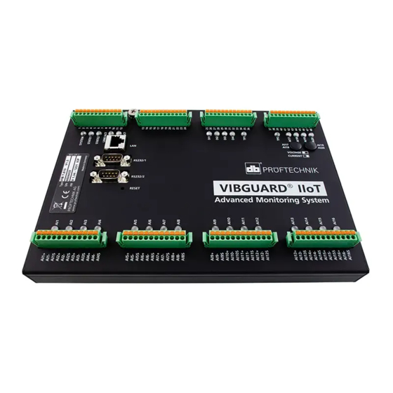
Page 18: System Module
Installation and Operation 4.1 System module VIB 7.800, VIB 7.810, VIB 7.811, VIB 7.815, VIB 7.820, VIB 7.825 Interfaces, display and operating elements 24V, PG : Connection for the system module supply. TX, RX : Ethernet connection, single wire PE : Protective earth terminal connected to PE terminal; used for contacting the system hou- sing, contacting the Ethernet socket, contacting the internal surge arresters. - Page 19 No faults user defined Flashing orange Update loading Digital inputs LED status DI1...DI4 Green Static signal pending Flashing green Dynamic signal pending, e.g. rpm signal Ethernet LED status LINK / ACT Green Connection to LAN established Data transfer active VIBGUARD IIoT...
-
Page 20: Power Supply
Installation and Operation 4.2 Power supply Interfaces, display, operating elements Output : In each case, two screw terminals for positive and negative poles. Both poles are equi- valent. Input : Connection terminals for the power line. DC on , (readiness indicator): LED lights up green if the voltage at the output is >... -
Page 21: Installation
Ethernet TCP/IP / 100 Mbit Network Connecting cables, general requirements Temperature range -20°C to +80°C [-4°F ... +176°F] Flammability flame retardant according to UL 2556 VW-1 or equivalent (IEC 60332-1-2 / IEC 60332-2-2) shielding > 85% Shielded cable VIBGUARD IIoT... -
Page 22: Mains Connection
5.2 Mains connection VIBGUARD IIoT meets the requirements for protection class I. The resulting necessary protective earth conductor establishes the connection between the protective earth connection of the VIBGUARD IIoT and the external pro- tective earth conductor system. The protective earth conductor is part of the mains connection cable. There must be no fuse, switch or circuit brea- ker in this connection. -
Page 23: Tools And Consumables
Ethernet e.g.: KLAUKE 167/HL (0,25 mm² / blue), Shield via KLAUKE 472/12 (1.5 mm² / black) Suitable strain relief for cable protection Cable tie or Velcro fastener to fix the cable in place Labels to mark the cable routes VIBGUARD IIoT... -
Page 24: Mounting
Installation and Operation 6 Mounting 6.1 Switch cabinet installation The variants VIB 7.8xx-PS are intended for installation on a top hat rail in an existing switch cabinet. The components are mounted and wired on a top hat rail for transportation purposes. Observe the following specifications prior to installation in the switch cabinet. - Page 25 The PE terminal remains connected to the power supply via the protective conductor. Take the power supply (1T1) off of the top hat rail: To do so, press the locking lever inward and then pull the power supply upward to remove it. VIBGUARD IIoT...
- Page 26 Installation and Operation Installing system components in the switch cabinet Place the system module and the power supply on the top hat rail in the switch cabinet and let them lock in place. Reinsert the PE terminal between the power supply and the system module. Note Ensuring that the power supply is cooled The power supply is designed for convection cooling and does not require an external air supply.
-
Page 27: Mounting The Protective Housing
Drill four holes in the intended location for attachment of the protective housing. The distances between the holes can be found in the dimension outlines (refer to ‚ "Dimensions" on page 15). If necessary, put assembly dowels in the drill holes. Fasten the protective housing with four M8 screws. VIBGUARD IIoT... -
Page 28: Rpm Sensor
The function display (LED) of the sensor responds during an RPM measurement. The RPM sensor supplies the raw signal to the VIBGUARD IIoT directly. It is not averaged. This is specifically necessary for variable speed units. - Page 29 Ensure that the arrangement is not excited by machine vibrations. If the RPM sensor is installed on the same retaining plate as the system RPM sensor, ensure that the system sensor is working flawlessly. Dimensions Measuring distance VIBGUARD IIoT...
-
Page 30: Electrical Connection
Installation and Operation 7 Electrical connection VIBGUARD IIoT is wired with the supply components at the factory. The following connections are to be established for installation on site: Connection to the mains supply Connection to the data network (Ethernet) Connection to the sensor lines and to the digital inputs and outputs... - Page 31 Terminal Designation Function 24V_1 Supply for system module PG_1 24V_2 Supply of additional equipment PG_2 24V_3 Supply of additional equipment PG_3 Protective con- Protective grounding ductor terminal of the housing and cur- rent path of the surge arrester. VIBGUARD IIoT...
-
Page 32: Data Line
Installation and Operation 7.2 Data line For the connection to the data network, the system module provides two equivalent ports: LAN connection terminal for Ethernet cable with pre-assembled RJ45 connector. Terminals 8 to 12 for Ethernet cable with open end. To connect an Ethernet cable with RJ45 connector, proceed as follows: Open a sensor cable gland (M32). - Page 33 Crimp suitable wire end ferrules on the wire ends. Connect the wires according to the following schema Re-tighten the cable gland. Ethernet connection via terminal block Terminal Designation Wire color orange/white orange gree/white green PE-LAN Screen VIBGUARD IIoT...
-
Page 34: External Process Variables
Installation and Operation 7.3 External process variables External process variables are fed into the CMS as an analog or digital signal by a control system or by a controller. They are potential-free when they are fed in. Process variables that can define an operating state and trigger dia- gnostic measurements must always be available. -
Page 35: Signal Lines
Installation and Operation 7.4 Signal lines The sensors in the VIBGUARD IIoT CMS are wired with shielded cables by default. Depending on the sensor type installed, coaxial or two-wire twisted-pair cables are used. The following rules must be observed when selecting the cable path: There are no frequency inverters or their supply lines in the wiring area. - Page 36 Installation and Operation Shield connection The PRÜFTECHNIK shield connector for sensor cables (VIB 6.726-100) allows you to prepare the sensor cable for connection to the shield terminal in just a few simple steps. The equipment supplied includes 100 solder sleeves. Per solder sleeve one single-core shield cable (AWG22 /0.38 mm²) is additionally required.
- Page 37 Connect a status signal each to the digital inputs DI1 to DI4. Relay outputs SYS OK and NO1 to NO3 are available for the connection to the digital inputs of external systems. Observe the connection specifications in this regard (see "Technical data" on page 13). VIBGUARD IIoT...
- Page 38 Installation and Operation To connect a signal cable to the terminal block, proceed as follows: Open one of the large cable glands (M32) using a suitable spanner (Size 36). Take out the seal. Remove a sealing insert. Place a cable loop in order to not put any strain on the connection during subsequent service work. Insert the open cable end through the seal (max.
-
Page 39: Terminal Diagram
DO1, DO2 configurable as required via OMNITREND Center Software NC1 (normally closed DO3 coupled with Alarm switch) Digital OUT 2 NO2 (normally open switch) COM2 (Common) NC2 (normally closed switch) Digital OUT 3 NO3 (normally open switch) COM3 (Common) NC3 (normally closed switch) VIBGUARD IIoT... - Page 40 Installation and Operation Digital inputs / outputs Terminal Designation Comment System OK AI4+ (Signal Plus) System status additionally indicated via status LED ‚STATE 1‘ on the system module. AI4- (Minus) Application, DIs: Digital IN 1 DI1+ (Plus) Trigger measurement tasks, counter input. DI1- (Minus) Digital IN 2 DI2+ (Plus)
- Page 41 AI14S (Screen) AI6S (Screen) Sensor AI15+ (Signal Plus) Sensor 7 AI7+ (Signal Plus) AI15- (Minus) AI7- (Minus) AI15S (Screen) AI7S (Screen) Sensor AI16+ (Signal Plus) Sensor 8 AI8+ (Signal Plus) AI16- (Minus) AI8- (Minus) AI16S (Screen) AI8S (Screen) VIBGUARD IIoT...
- Page 42 Installation and Operation Sensor 1 to 20 (analog IN) Signal System module Number / Ter- Designation type minal VIB 7.820, VIB 7.825 Sensor 17 AI17+ (Signal Plus) IEPE VIB 7.810, VIB 7.811, VIB 7.815 AI17- (Minus) VIB 7.800 Sensor 18 AI18+ (Signal Plus) AI18- (Minus) Channel...
-
Page 43: Connection Examples
Terminal 41: Signal (+) Terminal 42: Screen (-). Prepare the cable screen with the shield connection set (VIB 6.725-100). Dip switch on the left side = Voltage signal. Connection to the buffer (voltage output, e.g. 0 to 10V). VIBGUARD IIoT... - Page 44 Installation and Operation #2: IEPE sensor via twisted pair cable System module Terminal Instructions Signal at plus (+), VIB 7.810 49 to 96 GND at minus (-), VIB 7.811 49 to 84 Screen at screen terminal (S) VIB 7.815 49 to 72 Example for channel AI1 Terminal 49: Signal (+) Terminal 50: GND (-).
- Page 45 30 to 40 Signal at plus (TP1+), GND at minus (TP1-), (3-wires connection) Supply at supply plus (VTP1+). Example for channel TP1 Terminal 33: +24 V (supply) Terminal 35: Signal (DC) Terminal 36: GND/ screen RPM sensor, 3-wire VIBGUARD IIoT...
- Page 46 Installation and Operation #4: Sensor signal via buffered voltage output (Buffered OUT) System module Terminal Instructions Signal at plus (+), 41 to 48 Screen at minus (-), VIB 7.800 49 to 96 Leave the screen terminal (S) open. VIB 7.815 73 to 96 VIB 7.825 73 to 96...
- Page 47 Terminal 51: Screen (S). Prepare the cable screen with the shield connection set (VIB 6.725-100). CLD-type sensor VIB 6.195 with sensor cable, e.g. VIB 3.570-6. Note: Cables with no signal on their screen must be insulated on the sensor side. VIBGUARD IIoT...
- Page 48 Installation and Operation #6: CLD-type sensor via coaxial cable (RG58) System module Terminal Instructions Signal to plus (+), VIB 7.820 49 to 96 Screen to minus (-), VIB 7.825 49 to 72 Leave screen terminal (S) open Example for channel AI1 Terminal 49: Signal (+) Terminal 50: Screen (-).
-
Page 49: Commissioning
When using GL-certified CMS on wind turbines, the information in the applicable documents must be taken into account: - VIBGUARD IIoT - Commissioning Instructions - LIT 78.221 - VIBGUARD IIoT - Commissioning protocol - LIT 78.231 The system is configured via the PC software OMNITREND Center. -
Page 50: Troubleshooting
Installation and Operation 9 Troubleshooting The following errors may occur during operation: Symptom: Sensor status LED on the system module indicates a fault message (flashing orange). Possible cause: Sensor line is interrupted or has short circuited. Remedy: Check that the connections on the sensor and system are secure. Exchange any damaged cables Remedy: Check the cable connections with the PRÜFTECHNIK installation checker (item no. - Page 51 Proceed as follows to remove the system module: Disconnect the green terminal connectors from the system module to which cables are connected. Remove the system module from the top hat rail. VIBGUARD IIoT...
-
Page 52: Upkeep And Accessories
If necessary, the housing is to be cleaned with a damp cloth in order to ensure that the safety markings remain visi- ble. Damaged cables and connector plugs are to be replaced immediately. VIBGUARD IIoT does not require maintenance. The measurement database is to be backed up on a regular basis. 10.2 Accessories The following accessories are available for the VIBGUARD IIoT : OMNITREND Center PC-Software, Client-Server - item no. -
Page 53: Decommissioning
11 Decommissioning VIBGUARD IIoT is used exclusively for commercial purposes. The system and measuring equipment must not be dis- posed of using public waste disposal companies. Upon reaching the end of the period of use, you can dispose of the... - Page 54 Printed in Germany LIT 78.220.EN.03.2019 Fluke Deutschland GmbH Freisinger Str. 34 85737 Ismaning, Germany + 49 89 99616-0 www.pruftechnik.com Productive Maintenance Technology...
Need help?
Do you have a question about the VIBGUARD IIoT and is the answer not in the manual?
Questions and answers