Table of Contents
Advertisement
Quick Links
UG-2022-06
EVAL-IMI111T user guide
iMOTION™ MADK starter kit for IMI111T IPMs
About this document
Scope and purpose
This user guide provides an overview of the EVAL-IMI111T evaluation board including its main features, key
technical data, pin assignments, and mechanical dimensions.
EVAL-IMI111T is a full featured starter kit that includes the IMI111T iMOTION™ IPMs. It provides a fully-integrated,
turnkey, high voltage motor drive solution designed for high performance and high efficiency permanent magnet
synchronous motor (PMSM)/
pumps, and compressors. EVAL-IMI111T also comprises other necessary circuitry required for out-of-the-box
evaluation of IMI111T iMOTION™ IPMs, such as rectifier and EMI filter stage, as well as an isolated debugger
section with USB connection to the PC.
The EVAL-IMI111T starter kit was developed to support customers during their first steps in designing
applications with IMI111T iMOTION™ IPMs.
The available variants of the IMI111T starter kit are listed in Table 1.
Table 1
EVAL-IMI111T starter kit variants
Sales name
EVAL-IMI111T-026
EVAL-IMI111T-046
All the information provided in this user guide applies to both versions of the starter kit unless explicitly stated.
Intended audience
This user guide is intended for all technical specialists familiar with motor control and high power electronic
converters. The EVAL-IMI111T evaluation board is intended to be used under laboratory conditions only by
trained specialists.
Evaluation board
This board is used during design in for evaluation and measurement of characteristics, and proof of data sheet
specifications.
Note:
PCB and auxiliary circuits are NOT optimized for final customer design.
User guide
www.infineon.com
brushless direct current motor
Orderable part number
EVALIMI111T026TOBO1
EVALIMI111T046TOBO1
Please read the Important notice and the Safety precautions and the Warnings
(BLDC) motor drive applications such as fans,
iMOTION™ device
DC rating
IMI111T-026H
600V / 2A
IMI111T-046H
600V / 4A
page 1 of 37
V
Typ at 25°C
CE(sat)
1.5 V
1.4 V
V2.1
2022-12-9
Advertisement
Table of Contents

Subscribe to Our Youtube Channel
Related Manuals for Infineon EVAL-IMI111T


Summary of Contents for Infineon EVAL-IMI111T
-
Page 1: About This Document
This user guide provides an overview of the EVAL-IMI111T evaluation board including its main features, key technical data, pin assignments, and mechanical dimensions. EVAL-IMI111T is a full featured starter kit that includes the IMI111T iMOTION™ IPMs. It provides a fully-integrated, turnkey, high voltage motor drive solution designed for high performance and high efficiency permanent magnet... -
Page 2: Important Notice
Boards provided by Infineon Technologies. The design of the Evaluation Boards and Reference Boards has been tested by Infineon Technologies only as described in this document. The design is not qualified in terms of safety requirements, manufacturing and operation over the entire operating temperature range or lifetime. -
Page 3: Safety Precautions
EVAL-IMI111T user guide iMOTION™ MADK starter kit for IMI111T IPMs Safety precautions Safety precautions Note: Please note the following warnings regarding the hazards associated with development systems. Table 2 Safety precautions Warning: The DC link potential of this board is up to 1000 VDC. When measuring voltage waveforms by oscilloscope, high voltage differential probes must be used. -
Page 4: Table Of Contents
Thermal characterization ....................... 18 Thermal characteristic .......................... 20 Thermal PCB design ..........................21 Thermal protection ....................... 22 Getting started with EVAL-IMI111T ..................25 Hardware connection ..........................25 Getting started with iMOTION™ ......................26 UART function switching ........................27 PCB layout ..........................28 Application diagram ...................... -
Page 5: Introduction
Environmental conditions were considered in the design of the EVAL-IMI111T. The design was tested as described in this document but it is not qualified with regard to safety requirements or manufacturing and operating over the whole operating temperature range or lifetime. -
Page 6: Main Features
MADK starter kit for IMI111T IPMs Main features Main features EVAL-IMI111T starter kits are intended for evaluating the IMI111T series of iMOTION™ iMOTION™ IPMs. The main features [1] of IMI111T series are: Motion Control Engine (MCE) as ready-to-use controller solution for variable speed drives •... - Page 7 EVAL-IMI111T user guide iMOTION™ MADK starter kit for IMI111T IPMs Main features Table 3 lists all the important specifications of the EVAL-IMI111T evaluation board. Table 3 EVAL-IMI111T specifications Parameters Device Values Conditions Input Voltage EVAL-IMI111T-026 110 – 230 V EVAL-IMI111T-046...
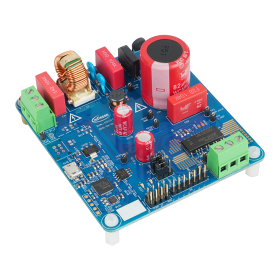
- Page 8 MADK starter kit for IMI111T IPMs Main features Figure 2 shows the functional groups on the top side of the EVAL-IMI111T-026 evaluation board. EVAL-IMI111T- 046 is similar to EVAL-IMI111T-026, except item 6 is the IMI111T-046H module. 1. Isolated onboard...
- Page 9 EVAL-IMI111T user guide iMOTION™ MADK starter kit for IMI111T IPMs Main features Figure 3 shows the functional groups on the bottom side of the Eval-IMI111T-026 evaluation board. This is same for both EVAL-IMI111T-046 and EVAL-IMI111T-026. 1. Auxiliary power supply 2. Current feedback stage...
-
Page 10: Pin Assignments
EVAL-IMI111T user guide iMOTION™ MADK starter kit for IMI111T IPMs Pin assignments Pin assignments Table 4 Pinout description for IMI111T [1] Name Type Description Serial port transmit output Serial port receive input Analog speed reference input Single-shunt current sense input... - Page 11 MADK starter kit for IMI111T IPMs Pin assignments IREF W/VSW W/VSW IMI111T pinout Error! Reference source not found. Figure 4 General information about the connectors of the EVAL-IMI111T evaluation board is provided in the following tables: Table 5 J1 connector description Name Details EARTH...
- Page 12 EVAL-IMI111T user guide iMOTION™ MADK starter kit for IMI111T IPMs Pin assignments Table 7 J3 connector description Name Details Connected to motor phase U Connected to motor phase V Connected to motor phase W Table 8 J4 jumper description Name...
-
Page 13: System Performance
System performance System performance To meet individual customer requirements and to help them make the EVAL-IMI111T evaluation board a basis for development or modification of their own boards, all necessary technical data such as schematics, layout, and components are included in this chapter. Figure 5, Table 6Figure 6, and Figure 7 provide an overview of the different parts of EVAL-IMI111T. -
Page 14: Dc-Link Voltage Measurement
EVAL-IMI111T user guide iMOTION™ MADK starter kit for IMI111T IPMs System performance Overview of power and control Figure 6 TP22 R114 15.8k R112 US1J-E3/61T C122 R115 100nF KBP206G R116 300R 100nF TP23 R113 630V 630V +3.3V LNK304DG C121 R117 300R... -
Page 15: Emi Filter
DCBSENSE 13.3k 4.7nF DC bus sense resistor on the EVAL-IMI111T evaluation board Figure 8 The DCBSENSE voltage is read by the VDC pin of the controller. With 13.3 kΩ as pull-down resistor, the DCBSENSE voltage causes a range of 0 to 3.3 V on the pin reflecting a DC bus voltage range of 0 to 500 V. -
Page 16: Auxiliary Power Supply
Figure 10 Auxiliary power supply Figure 11 shows the schematic of the auxiliary power supply available on the EVAL-IMI111T board. The circuit includes a LNK304 that is used to generate 15 V directly from the DC bus. V is connected to the gate driver inside the iMOTION™... - Page 17 3.3 �� Internal gain can be set via the iMOTION™ Solution Designer and the default value for EVAL-IMI111T is equal to 3. Particular attention has to be paid when setting the internal gain to avoid saturating the ADC; it can cause a continuous GateKill fault status.
-
Page 18: Thermal Characterization
EVAL-IMI111T user guide iMOTION™ MADK starter kit for IMI111T IPMs Thermal characterization Thermal characterization Figure 13, Figure 14, Figure 15, Figure 16, Figure 17, and Figure 18 show the thermal characterizations of the two part numbers. The tests were performed under the following conditions: = 20°C, input voltage = 220 Vrms (V... - Page 19 EVAL-IMI111T user guide iMOTION™ MADK starter kit for IMI111T IPMs Thermal characterization 6kHz, 2-phase PWM 6kHz, 2-phase PWM IMI111T-046H IMI111T-046H IMI111T-026H IMI111T-026H Motor Current (mA Input Power (W) Thermal Characterization of IMI111T-026H vs IMI111T-046H, 2-phase PWM, 6 kHz, FR4 PCB with...
-
Page 20: Thermal Characteristic
EVAL-IMI111T user guide iMOTION™ MADK starter kit for IMI111T IPMs Thermal characterization 3-phase PWM, ∆Tca=80℃ IMI111T-046H IMI111T-026H PWM freq (kHz) Thermal Characterization of IMI111T-026H vs IMI111T-046H, 3-phase PWM, ΔTca = 80°C, FR4 PCB Figure 18 with 2 oz copper Thermal characteristic... -
Page 21: Thermal Pcb Design
EVAL-IMI111T user guide iMOTION™ MADK starter kit for IMI111T IPMs Thermal characterization Thermal PCB design IMI111T relies on the leads to transfer thermal dissipation from the power devices to the PCB. There are several critical pins that need attention to achieve improved thermal performance of the module. Figure 20 shows the pins critical for thermal dissipation. -
Page 22: Thermal Protection
The script that is used for overtemperature protection in EVAL-IMI111T is shown in Code Listing 1, Code Listing 2 and Code Listing 3. The script has been implemented to stop the motor when the sensed temperature reaches 91°C (shutdown temperature) and to restart the motor when the sensed temperature goes below 60°C (restart... - Page 23 EVAL-IMI111T user guide iMOTION™ MADK starter kit for IMI111T IPMs Thermal protection 018: 019: /**************************************************************************************************** 020: **************/ /*Task0 init function*/ 021: Script_Task0() 022: 023: Inter_temperature=MCEOS.InternalDieTemp; 024: if((Inter_temperature < t_hyst)&&(flag == 1)) 025: /*If t_hyst < temperature < t_shutdown, motor is still in stop condition and it is not able to...
- Page 24 EVAL-IMI111T user guide iMOTION™ MADK starter kit for IMI111T IPMs Thermal protection IMI111T-026H IMI111T-046H Correlation between the case temperature and the internal temperature readout Figure 22 User guide 24 of 37 V2.1 2022-12-9...
-
Page 25: Getting Started With Eval-Imi111T
EVAL-IMI111T user guide iMOTION™ MADK starter kit for IMI111T IPMs Getting started with EVAL-IMI111T Getting started with EVAL-IMI111T This chapter provides details on setting up the system and getting started with the iMOTION™ development platform. The iMOTION™ development tool, iMOTION™ Solution Designer is required to set up the system, and to control and fine-tune the system performance to match a user’s actual needs. -
Page 26: Getting Started With Imotion
EVAL-IMI111T user guide iMOTION™ MADK starter kit for IMI111T IPMs Getting started with EVAL-IMI111T Ensure the jumper on J2 is connected to “RXD0” and “RX/DIR” and the jumper on J4 is connected to “TXD0” and “TX/PGOUT”. Connect the PC-USB connector to the onboard debugger via the USB cable. -
Page 27: Uart Function Switching
EVAL-IMI111T user guide iMOTION™ MADK starter kit for IMI111T IPMs Getting started with EVAL-IMI111T UART function switching To use Pin1 and Pin2 as UART, users must ensure that the RXD0” and “RX/DIR” of jumper J2 are connected and “TXD0” and “TX/PGOUT” of jumper J4 are connected. -
Page 28: Pcb Layout
The layout of this board can be used for different voltage or power classes. The power PCB is a 2-layer PCB. Get in touch with Infineon’s technical support team to get detailed information and the latest gerber files. Figure 26 shows the top assembly print of the evaluation board. - Page 29 MADK starter kit for IMI111T IPMs PCB layout Figure 27 shows the bottom assembly print of the evaluation board. Bottom assembly print of the EVAL-IMI111T evaluation board Figure 27 The top layer of the PCB is shown in Figure 28.
- Page 30 EVAL-IMI111T user guide iMOTION™ MADK starter kit for IMI111T IPMs PCB layout Figure 29 shows the bottom layer routing of the PCB. Bottom layer of EVAL-IMI111T Figure 29 User guide 30 of 37 V2.1 2022-12-9...
-
Page 31: Application Diagram
EVAL-IMI111T user guide iMOTION™ MADK starter kit for IMI111T IPMs Application diagram Application diagram Application diagram Block diagram of an application using IMI111T Figure 30 User guide 31 of 37 V2.1 2022-12-9... -
Page 32: Bill Of Materials
MADK starter kit for IMI111T IPMs Bill of materials Bill of materials The complete bill of material (BOM) is available in the download section of Infineon’s homepage. A log in is required to download this material. Table 11 BOM of the most important/critical parts Qty. - Page 33 EVAL-IMI111T user guide iMOTION™ MADK starter kit for IMI111T IPMs Bill of materials Qty. Part description Designator Part Number Manufacturer RES / STD / 250mR / RL1206FR-070R25L Yageo 250mW / 1% / 600ppm/K / -55 ℃ to 155 ℃ / 1206 / SMD / - RES / NTC / 15R / 1.4W / -...
- Page 34 EVAL-IMI111T user guide iMOTION™ MADK starter kit for IMI111T IPMs Bill of materials Qty. Part description Designator Part Number Manufacturer Micro-USB 2.0 Standard, X101 ZX62-AB-5PA(31) Hirose Connectors Type AB, Bottom Mount, Shell SMT User guide 34 of 37 V2.1 2022-12-9...
-
Page 35: References And Appendices
11.2 Additional information To initiate testing, customers can order the iMOTION™ link. Details are provided in Table 13. Infineon components on the board are also listed in Table 13. Customers can visit the corresponding webpage for more information. Table 13... -
Page 36: Revision History
EVAL-IMI111T user guide iMOTION™ MADK starter kit for IMI111T IPMs Table of contents Revision history Document Date of release Description of changes version V 1.0 2022/6/8 Initial version V 2.0 2022/9/13 Changed description of section 7.2 and added section 7.3 V2.1... - Page 37 WARNINGS 81726 Munich, Germany Due to technical requirements products may contain dangerous substances. For information on the types in question please contact your nearest Infineon © 2023 Infineon Technologies AG. Technologies office. All Rights Reserved. Except as otherwise explicitly approved by Infineon...
Need help?
Do you have a question about the EVAL-IMI111T and is the answer not in the manual?
Questions and answers