Table of Contents
Advertisement
Quick Links
AN2019-17 EVAL-IMM101T User Manual
EVAL-IMM101T User Manual
iMOTION™ MADK Starter Kit for IMM101T Smart IPMs
About this document
Scope and purpose
This application note provides an overview of the evaluation board EVAL-IMM101T including its main features,
key technical data, pin assignments and mechanical dimensions.
EVAL-IMM101T is a full-featured Starter Kit including an IMM101T Smart IPM which provides a fully-integrated,
turnkey high-voltage motor drive solution designed for high-performance, high-efficiency PMSM/BLDC motor
drive applications such as fans, pumps and compressors. EVAL-IMM101T also comprises other necessary circuitry
required for "out-of-the-box" evaluation of IMM101T Smart IPMs, such as rectifier and EMI filter stage, as well as
isolated debugger section with USB connection to the PC.
The Starter Kit EVAL-IMM101T was developed to support customers during their first steps designing
applications with IMM101T Smart IPM.
The available variants of the IMM101T Starter Kit are listed in Table 1:
Table 1
EVAL-IMM101T Starter Kit variants
Sales Name
EVAL-IMM101T-015
EVAL-IMM101T-046
All the information provided in this User Manual applies to both versions of the Starter Kit unless explicitely
stated that the specific information is valid only for one particular variant.
Intended audience
This application note is intended for all technical specialists who are familiar with motor control and high power
electronics converter and the EVAL-IMM101T evaluation board is intended to be used under laboratory
conditions only by trained specialists.
www.infineon.com
iMOTION Device
IMM101T-015M
IMM101T-046M
Please read the Important Notice and Warnings at the end of this document
Output Rating
500V / 1A
600V / 4A
page 1 of 38
R
Typ at 25°C
DS(ON)
4.8 Ω
1.26 Ω
Advertisement
Table of Contents

Related Manuals for Infineon iMOTION EVAL-IMM101T Series


Summary of Contents for Infineon iMOTION EVAL-IMM101T Series
-
Page 1: About This Document
This application note is intended for all technical specialists who are familiar with motor control and high power electronics converter and the EVAL-IMM101T evaluation board is intended to be used under laboratory conditions only by trained specialists. Please read the Important Notice and Warnings at the end of this document www.infineon.com page 1 of 38... -
Page 2: Table Of Contents
EVAL-IMM101T Smart IPM evaluation board application note Table of contents Table of contents About this document ........................1 Table of contents ..........................2 Safety precautions ......................... 3 Introduction .......................... 4 Main features ......................... 5 Pin assignments ........................8 Schematics and Layout ......................10 DC-Link Voltage Measurement ...................... -
Page 3: Safety Precautions
EVAL-IMM101T Smart IPM evaluation board application note Safety precautions Safety precautions In addition to the precautions listed throughout this manual, please read and understand the following statements regarding hazards associated with development systems. Table 2 Precautions Attention: The ground potential of the EVAL-IMM101T system is biased to a negative DC bus voltage potential. -
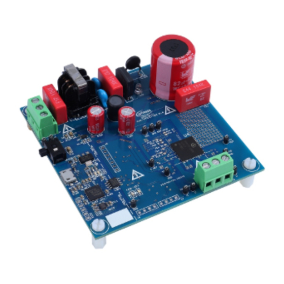
Page 4: Introduction
Introduction Introduction The EVAL-IMM101T Starter Kit is designed to give an easy-to-use motor drive solution based on the Infineon's IMM101T Smart IPM.The board is equipped with all assembly groups for sensorless field oriented control (FOC). It contains a single-phase AC-connector, EMI filter, rectifier and 3-phase output for connecting the motor. The power stage also contains source shunt for current sensing and a voltage divider for DC-link voltage measurement. -
Page 5: Main Features
EVAL-IMM101T Smart IPM evaluation board application note Main features Main features EVAL-IMM101T Starter Kits are intended for evaluation of the IMM101T series of iMOTION™ Smart IPMs. The main features of IMM101T series are: Motion control engine (MCE2.0) as ready-to-use controller solution for variable speed drives ... - Page 6 EVAL-IMM101T Smart IPM evaluation board application note Main features Table 3 lists all the important specifications of the evaluation board EVAL-IMM101T. Table 3 EVAL-IMM101T specifications Parameters Device Values Conditions Input Voltage EVAL-IMM101T-015 110 – 230 V EVAL-IMM101T-046 Output Current per phase EVAL-IMM101T-015 355 mA = 25°C, t...
- Page 7 EVAL-IMM101T Smart IPM evaluation board application note Main features Figure 2 points out the functional groups on the top side of the EVAL-IMM101T evaluation board. 1. Isolated on board debugger with USB connector 2. J1 – AC line connector 3. EMI filter 4.
-
Page 8: Pin Assignments
EVAL-IMM101T Smart IPM evaluation board application note Pin assignments Pin assignments Table 4 Pinout description for IMM101T – single motor control use case – typical configuration Name Type Description Vbus scaled Vbus scaled ADC input CREF Analog Overcurrent Comparator threshold DAC Digital V input [3.3V –... - Page 9 EVAL-IMM101T Smart IPM evaluation board application note Pin assignments General information about the connectors of the EVAL-IMM101T evaluation board is listed in Table 5, Table 6 and Table 7, Table 8 and Table 9. Table 5 J5 connector description Name Details Ground D_F_VSP_IN...
-
Page 10: Schematics And Layout
EVAL-IMM101T Smart IPM evaluation board application note Schematics and Layout Schematics and Layout To meet individual customer requirements and make the EVAL-IMM101T evaluation board a basis for development or modification of their own boards, all necessary technical data like schematics, layout and components are included in this chapter. - Page 11 EVAL-IMM101T Smart IPM evaluation board application note Schematics and Layout Figure 6 Power and control overview Figure 7 Power supplies overview 11 of 38...
-
Page 12: Dc-Link Voltage Measurement
EVAL-IMM101T Smart IPM evaluation board application note Schematics and Layout DC-Link Voltage Measurement Figure 8 provides the DC bus sense resistor details. Figure 8 DC bus sense resistor on EVAL-IMM101T evaluation board The DCBSENSE voltage is read by pin P2.10 of the controller. With 13.3 kΩ as pull down resistor, the DCBSENSE voltage results in the range of 0 to 3.3 V on the pin reflecting a DC bus voltage range of 0 to 500 V. -
Page 13: Auxiliary Power Supply
EVAL-IMM101T Smart IPM evaluation board application note Schematics and Layout Figure 10 Schematic of the 3-phase inverter section using Smart IPM IMM101T on EVAL-IMM101T Auxiliary power supply Figure 11 depicts the schematic of the auxiliary power supply available on the EVAL-IMM101T board. The circuit includes a LNK304 that is used to generate 15 V directly from the DC bus. -
Page 14: Current Measurement Shift Stage And Overcurrent Threshold
EVAL-IMM101T Smart IPM evaluation board application note Schematics and Layout Figure 11 Power supply section of the EVAL-IMM101T evaluation board The 3.3 V can be generated also via isolated on board power supply (R1S-0533) enabling the switch on the left side of the board. - Page 15 EVAL-IMM101T Smart IPM evaluation board application note Schematics and Layout In leg shunt configuration, the resistors RS1, RS2 and RS3 are purposed to generate voltages proportional to the source currents of the low side power MOSFETs. These voltages are shifted using the shift stages in Figure 13 and they are measured at pins P2.9, P2.6, P2.2 respectively.
-
Page 16: Thermal Characterization
EVAL-IMM101T Smart IPM evaluation board application note Thermal Characterization Thermal Characterization Figure 14, Figure 15, Figure 16, Figure 17, Figure 18, Figure 19 show the thermal characterizations of the three part numbers. The tests reported in Figure 14, Figure 15, Figure 16 have been performed under the following conditions: t =25°C, different phase current values until the case reaches 105°C, two PWM frequencies (6 and 16kHz) and two different modulation types (3-phase modulation and 2-phase flat bottom modulation). - Page 17 EVAL-IMM101T Smart IPM evaluation board application note Thermal Characterization IMM101T-046M, Thermal Characterization t =25°C 3-phase modulation 16kHz 2-phase modulation 16kHz 3-phase modulation 6kHz 2-phase modulation 6kHz 180,0 230,0 280,0 330,0 380,0 430,0 480,0 530,0 580,0 630,0 Phase Current [mA IMM101T-046M Thermal Characterization, t =25°C, different phase current values until the Figure 15 case reaches 105°C, FR4 PCB with 2oz copper...
- Page 18 EVAL-IMM101T Smart IPM evaluation board application note Thermal Characterization IMM101T-015M, Thermal Characterization t =60°C 2-phase modulation 16 kHz 3-phase modulation 6 kHz 2-phase modulation 6 kHz 190,0 210,0 230,0 250,0 270,0 290,0 310,0 330,0 Phase Current [mA IMM101T-015M Thermal Characterization, t =60°C, different phase current values until the Figure 17 case reaches 105°C, FR4 PCB with 2oz copper...
-
Page 19: Thermal Characteristic
EVAL-IMM101T Smart IPM evaluation board application note Thermal Characterization IMM101T-56M, Thermal Characterization t =60°C 2-phase modulation 16 kHz 3-phase modulation 6 kHz 2-phase modulation 6 kHz 190,0 240,0 290,0 340,0 390,0 440,0 490,0 540,0 590,0 Phase Current [mA IMM101T-056M Thermal Characterization, t =60°C, different phase current values until the Figure 19 case reaches 105°C, FR4 PCB with 2oz copper... -
Page 20: Thermal Protection
Please always download the latest MCE software package for IMM101T from the Infineon website (www.infineon.com/imotion-software) and refer to the corresponding iMOTION™ MCE Software Reference Manual to get the list of all supported features. Also refer to the “How to use iMOTION™... - Page 21 EVAL-IMM101T Smart IPM evaluation board application note Thermal Protection Script_Task0() temperature=InternalTemp; if((temperature<t_hyst)&&(flag==1)) /*If t_hyst<temperature<t_shutdown and the motor is in stop condition, it is not possible to restart*/ flag=0; Command=1; if(temperature>t_shutdown) /*If temperature>t_shutdown, motor is stopped*/ Command=0; flag=1; if(flag==1) Command=0; Note: The script function in MCEWizard Options page has to be enabled in order to allow the script functionality to be active.
-
Page 22: Getting Started With Eval-Imm101T
These tools are available for download via Infineon website (http://www.infineon.com/imotion-software). All supported tool and software versions are listed there. Please visit this page periodically to check for tool/software updates. - Page 23 EVAL-IMM101T Smart IPM evaluation board application note Getting started with EVAL-IMM101T Figure 21 MCEWizard and MCEDesigner welcome pages The steps needed to run the motor are: 1. Connect PC-USB connector on the on-board debugger to the PC via USB cable 2.
- Page 24 EVAL-IMM101T Smart IPM evaluation board application note Getting started with EVAL-IMM101T Figure 22 MCEWizard Verify and Save page 4. Connect motor phase outputs to the motor 5. Connect AC power to power input connector and power on the system or give the 3.3 V supply to the controller switching on the switch on the left side of the board (the communication is in any case isolated).
- Page 25 EVAL-IMM101T Smart IPM evaluation board application note Getting started with EVAL-IMM101T Figure 24 MCEDesigner programmer page 10. Start the motor by clicking the green traffic light button in the control bar 11. Once the firmware has been programmed, in case a new parameters file has to be programmed, follow the same instructions given in step 9.
-
Page 26: Pcb Layout
EVAL-IMM101T Smart IPM evaluation board application note PCB Layout PCB Layout The layout of this board can be used for different voltage or power classes. The power PCB is a two layer PCB. Get in contact with our technical support team to get more detailed information and the latest Gerber-files. Figure 25 illustrates the top assembly print of the evaluation board Figure 25 Top assembly print of the EVAL-IMM101T evaluation board... - Page 27 EVAL-IMM101T Smart IPM evaluation board application note PCB Layout The top layer of the PCB is provided in Figure 27. Figure 27 Top layer of the EVAL-IMM101T Figure 28 illustrates the bottom layer routing of the PCB. Figure 28 Bottom layer of EVAL-IMM101T 27 of 38...
-
Page 28: Application Diagrams And Application Use Cases
EVAL-IMM101T Smart IPM evaluation board application note Application Diagrams and Application Use Cases Application Diagrams and Application Use Cases 10.1 Application Diagrams VBUS 3.3V V DD V CC JTAG UART HIN 1 Digit al I/O GATE HIN 2 DRIVE R HIN 3 A IN0/V bus A IN1/V sp... -
Page 29: Imm101T Application Use Cases
EVAL-IMM101T Smart IPM evaluation board application note Application Diagrams and Application Use Cases 10.2 IMM101T Application Use Cases This chapter provides more details about most common application use cases for IMM100 series’ devices, including necessary passive components and pin connections. 10.2.1 Sensorless Single Shunt The sensorless single-shunt use case shown below is a most common application use case for IMM100 devices,... -
Page 30: Sensorless Leg Shunt
EVAL-IMM101T Smart IPM evaluation board application note Application Diagrams and Application Use Cases 10.2.2 Sensorless Leg Shunt The sensorless leg shunts configuration may be used in applications where only very low acoustic noise is requrired. Vbus I_Rs3 Vbus Vbus sense 13.3k 3.3V RXD0... -
Page 31: Configuration With 2 Hall Sensors
EVAL-IMM101T Smart IPM evaluation board application note Application Diagrams and Application Use Cases 10.2.3 Configuration with 2 Hall Sensors Vbus Vbus Vbus sense 13.3k 3.3V 3.3V 1.2k RXD0 P0.14 P0.15 TXD0 P2.0 / P4.6 3.3V P2.2 3.3V Vss2 1.2k P2.6 P2.9 Vbus sense... -
Page 32: Bill Of Materials Of Eval-Imm101T
EVAL-IMM101T Smart IPM evaluation board application note Bill of Materials of EVAL-IMM101T Bill of Materials of EVAL-IMM101T Table 10 Bill of materials Qty. Part description Designator Part Number Manufacturer KBP206G 2A 600V DIP-4 KBP206G Yunhui CAP CER 10UF 10V X5R 885012107010 Wurth Electronics Inc. - Page 33 EVAL-IMM101T Smart IPM evaluation board application note Bill of Materials of EVAL-IMM101T Qty. Part description Designator Part Number Manufacturer CAP CER 4.7UF 10V X5R C112 885012106012 Wurth Electronics Inc. 0603 CAP ALUM 220UF 20% C120 860020574012 Wurth Electronics Inc. 35V RADIAL CAP CER 0.1UF 50V X7R 121, C123, 885012207098...
- Page 34 EVAL-IMM101T Smart IPM evaluation board application note Bill of Materials of EVAL-IMM101T Qty. Part description Designator Part Number Manufacturer R3, R6, R9, RES SMD 100ohm 1/10W RT0603DRD07100R Yageo 0603 1% R12, R13 R10, R119 Yageo RES SMD 9.1Kohm 1/8W RC0805JR-079K1L Yageo 0805 RES SMD 47ohm 1/10W...
- Page 35 PURP 8SOIC CONN RCPT USB2.0 X101 ZX62-AB-5PA Hirose Electric Co Ltd MICRO AB SMD RA IC REG LINEAR 3.3V 1A IFX1117MEV33HTM U3,U102 Infineon Technologies SOT223-4 IC MCU 32BIT 256KB XMC4200-Q48F256 U101 Infineon Technologies FLASH 48VQFN TVS DIODE 17VC WLL-2-1 V101, V102...
-
Page 36: Reference
MCEWizard_V2.0.1.1 User Guide MCEDesigner_V2.0.1.1 Application Guide How to Use iMOTION™ Script Language Application Note Notice: Infineon’s Product Registration is online now. Register your board and download more information. Three easy steps are required for registration: 1. Go to www.Infineon.com and click on myInfineon;... -
Page 37: Revision History
EVAL-IMM101T Smart IPM evaluation board application note Revision history Revision history Document Date of release Description of changes version V1.0 2019-07-17 Initial version V1.1 2019-0722 Typo corrections 37 of 38... - Page 38 Infineon Technologies, any kind, including without limitation warranties of Infineon Technologies’ products may not be used in any Do you have a question about any aspect non-infringement of intellectual property rights of any...
- Page 39 Mouser Electronics Authorized Distributor Click to View Pricing, Inventory, Delivery & Lifecycle Information: Infineon EVAL-IMM101T-046TOBO1 EVAL-IMM101T-015TOBO1...
Need help?
Do you have a question about the iMOTION EVAL-IMM101T Series and is the answer not in the manual?
Questions and answers