
Subscribe to Our Youtube Channel
Related Manuals for Garland P10GMSFE-5


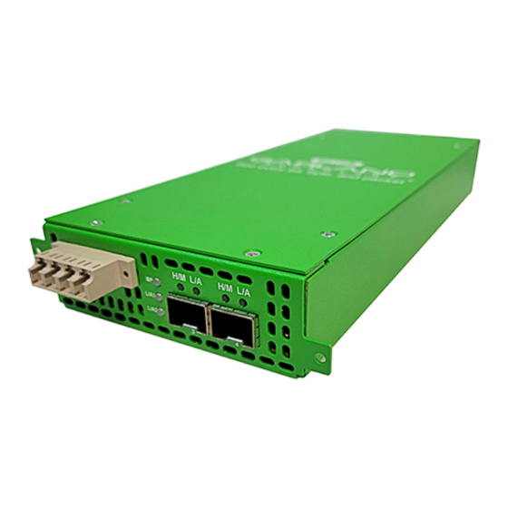
Summary of Contents for Garland P10GMSFE-5
- Page 1 User Guide P10GMSFE-5 P10GMSFE-6 P10GMSFE-7 P10GMSFE-8 P10GMSFE-9 P10GSSFE-5 P10GSSFE-6 P10GSSFE-7 P10GSSFE-8 P10GSSFE-9 01/2023 Release Version: 4.22.1...
- Page 2 The Garland Technology trademarks, service marks ("Marks") and other Garland Technology trademarks are the property of Garland Technology, LLC. PacketMAX Series products of marks are trademarks or registered trademarks of Garland Technology, LLC. You are not permitted to use these Marks without the prior written consent of Garland Technology.
-
Page 3: Table Of Contents
Add SSL Certificate Disable Using Uploaded SSL Certificate Date & Time Timezone Manually Set Date & Time NTP No Authentication (Symmetric) NTP Authentication (Symmetric) Syslog Garland Technology | 716.242.8500 | www.garlandtechnology.com Copyright © 2023 Garland Technology, LLC. All rights reserved. - Page 4 Config Map Save Modify a Config Map Delete Config Map Method 1 Method 2 Enable/Disable Config Map Disable Config Map Enable Config Map 8. Port Info Garland Technology | 716.242.8500 | www.garlandtechnology.com Copyright © 2023 Garland Technology, LLC. All rights reserved.
- Page 5 User Guide XtraTAP | P10GxxFE-X | 4.22.1 Port Configuration Port Description Set Speed Mode Port Statistics Garland Technology | 716.242.8500 | www.garlandtechnology.com Copyright © 2023 Garland Technology, LLC. All rights reserved.
-
Page 6: Dashboard
Span Port Link/Activity LED Port 4 H/M * The L/A1, L/A2, Port 3 L/A and Port 4 L/A LEDs only indicate link in the GUI. Garland Technology | 716.242.8500 | www.garlandtechnology.com Copyright © 2023 Garland Technology, LLC. All rights reserved. -
Page 7: Breakout
Breakout Port Link/Activity LED Port 4 H/M * The L/A1, L/A2, Port 3 L/A and Port 4 L/A LEDs only indicate link in the GUI. Garland Technology | 716.242.8500 | www.garlandtechnology.com Copyright © 2023 Garland Technology, LLC. All rights reserved. -
Page 8: Filter
Filter Port Link/Activity LED Port 4 H/M * The L/A1, L/A2, Port 3 L/A and Port 4 L/A LEDs only indicate link in the GUI. Garland Technology | 716.242.8500 | www.garlandtechnology.com Copyright © 2023 Garland Technology, LLC. All rights reserved. -
Page 9: Aggregate
Aggregate Port Link/Activity LED Port 4 H/M * The L/A1, L/A2, Port 3 L/A and Port 4 L/A LEDs only indicate link in the GUI. Garland Technology | 716.242.8500 | www.garlandtechnology.com Copyright © 2023 Garland Technology, LLC. All rights reserved. -
Page 10: Filter Tap
LED Indications Port 1 L/A1 Network Port Link/Activity LED Port 2 L/A2 Network Port Link/Activity LED Port 3 L/A Breakout/Aggregate Port Link/Activity LED Port 3 H/M Garland Technology | 716.242.8500 | www.garlandtechnology.com Copyright © 2023 Garland Technology, LLC. All rights reserved. -
Page 11: System
The following configuration options may be displayed, modified, enabled or disabled under the System panel. System Info SNMP General Export Configuration Admin Import Configuration Network Settings Software Upgrade Date & Time Reboot Syslog Garland Technology | 716.242.8500 | www.garlandtechnology.com Copyright © 2023 Garland Technology, LLC. All rights reserved. -
Page 12: System Info
The General System Settings panel will be displayed. 2. Select Edit Configuration. 3. Enter the desired Chassis Name. 4. Enter the desired Key Press Timeout. 5. Select Save to save updates. Garland Technology | 716.242.8500 | www.garlandtechnology.com Copyright © 2023 Garland Technology, LLC. All rights reserved. -
Page 13: Admin
OPER and NOC. All three groups may be modified, however only the OPER and NOC groups may be deleted. 1. Select Groups + to create a new group. The Create New Group panel will be displayed. Garland Technology | 716.242.8500 | www.garlandtechnology.com Copyright © 2023 Garland Technology, LLC. All rights reserved. -
Page 14: Local Authentication Disable
2. Enter the IP Address, IPv4 or IPv6. 3. Enter the Secret Word, (optional). 4. Select Save to save updates. 5. Select Cancel to return the Admin Settings panel. Garland Technology | 716.242.8500 | www.garlandtechnology.com Copyright © 2023 Garland Technology, LLC. All rights reserved. -
Page 15: Tacacs Test
The TACACS Test option will be active only if TACACS authentication has previously been enabled. 1. Select TACACS Test. The TACACS Test panel will appear. 2. Select Secondary. Garland Technology | 716.242.8500 | www.garlandtechnology.com Copyright © 2023 Garland Technology, LLC. All rights reserved. -
Page 16: Tacacs Ping Test
Using Uploaded SSL Certificate 1. Select Network Settings. The Network Settings panel will be displayed with the current configuration. IPv4 / Disable 1. Deselect Enable IPv4. Garland Technology | 716.242.8500 | www.garlandtechnology.com Copyright © 2023 Garland Technology, LLC. All rights reserved. -
Page 17: Add Ssl Certificate
2. Select Choose File for Select Certificate. 3. Select the desired cert.pem file. 4. Select Open. 5. Select the Choose File for Select Key File. 6. Select the desired key.pem file. Garland Technology | 716.242.8500 | www.garlandtechnology.com Copyright © 2023 Garland Technology, LLC. All rights reserved. -
Page 18: Disable Using Uploaded Ssl Certificate
2. Select the desired Timezone using the pull down panel. 3. Select Save. 4. Select Cancel to return to the Date & Time Settings panel. Garland Technology | 716.242.8500 | www.garlandtechnology.com Copyright © 2023 Garland Technology, LLC. All rights reserved. -
Page 19: Ntp Authentication (Symmetric)
If IPv6 is desired, then an IPv6 management interface must be assigned. The system allows for an IPv4 and IPv6 management interface to be assigned simultaneously. 1. Select Edit Settings. Garland Technology | 716.242.8500 | www.garlandtechnology.com Copyright © 2023 Garland Technology, LLC. All rights reserved. -
Page 20: Syslog Test
9. Select Cancel to return the Syslog Configuration panel. Syslog Test 1. Select Syslog Test. The GUI message will be displayed,”Syslog Test Successful!”. 2. Verify the Syslog Test Message on the Syslog server. Garland Technology | 716.242.8500 | www.garlandtechnology.com Copyright © 2023 Garland Technology, LLC. All rights reserved. -
Page 21: Snmp
14. Select Cancel to return the SNMP Configuration panel. SNMP Test 1. Select SNMP Test. The GUI message will be displayed,”Test Successful!”. 2. Verify the SNMP Test Message on the MIB Browser. Garland Technology | 716.242.8500 | www.garlandtechnology.com Copyright © 2023 Garland Technology, LLC. All rights reserved. -
Page 22: Export Configuration
This option allows the unit to be rebooted. The traffic will be affected for up to 1 minute. 1. Select Reboot. The Reboot Device panel will be displayed. 2. Select Reboot. The unit will present an “Are you sure?” message. Garland Technology | 716.242.8500 | www.garlandtechnology.com Copyright © 2023 Garland Technology, LLC. All rights reserved. -
Page 23: Span Mode
In this mode, the network port 1 and span ports 2, 3 and 4 are defined by the system. Port 1 is an ingress only port. Ports 2, 3 and 4 are egress only ports. Garland Technology | 716.242.8500 | www.garlandtechnology.com Copyright © 2023 Garland Technology, LLC. All rights reserved. -
Page 24: Breakout Mode
The traffic ingressed in port 1 is egressed out port 3. The traffic ingressed in port 2 is egressed out port 4. Garland Technology | 716.242.8500 | www.garlandtechnology.com Copyright © 2023 Garland Technology, LLC. All rights reserved. -
Page 25: Filter Mode
In this mode, the unit functions as a 4 port packet broker. The traffic that is passed between the ports is determined by the config map(s) and filter(s) created. Config maps may be created between all four ports as desired. Garland Technology | 716.242.8500 | www.garlandtechnology.com Copyright © 2023 Garland Technology, LLC. All rights reserved. -
Page 26: Packet Broker
Figure 4 Filter Mode Packet Broker The following configuration options may be displayed, modified, enabled or disabled under the Packet Broker panel. Filter Templates Config Maps Statistics Garland Technology | 716.242.8500 | www.garlandtechnology.com Copyright © 2023 Garland Technology, LLC. All rights reserved. -
Page 27: Filter Templates
Create Config Map panel and may be used to create an ingress or egress filter. Template options may be modified when applied to a config map. Any option modification made will Garland Technology | 716.242.8500 | www.garlandtechnology.com Copyright © 2023 Garland Technology, LLC. All rights reserved. -
Page 28: Config Map
10. The filter template may be deleted by selecting the Red X. Config Map Config maps are unidirectional connections between ingress port(s) to egress port(s) and/or a load balancing group. 1. Select Configuration Maps. Garland Technology | 716.242.8500 | www.garlandtechnology.com Copyright © 2023 Garland Technology, LLC. All rights reserved. -
Page 29: Ingress
Drag the port to the Ingress panel and release. Ports may be added in any combination. If ports 1 and 2 are added, then the traffic from the ports will be aggregated. Figure 5 Ingress Garland Technology | 716.242.8500 | www.garlandtechnology.com Copyright © 2023 Garland Technology, LLC. All rights reserved. -
Page 30: Filters
4. Select Accept once all desired options have been modified. 5. Remove a Filter Template by selecting the Red X. Garland Technology | 716.242.8500 | www.garlandtechnology.com Copyright © 2023 Garland Technology, LLC. All rights reserved. -
Page 31: Egress
3. Select Cancel to disregard. Modify a Config Map 1. Modify a config map by selecting the Edit icon. Modifications may be made using the create sections previously discussed. Garland Technology | 716.242.8500 | www.garlandtechnology.com Copyright © 2023 Garland Technology, LLC. All rights reserved. -
Page 32: Config Map Statistics
6. Select the Egress Filter icon to display the statistics. Delete Config Map 1. Select the Delete in the Delete column for the desired config map(s). Garland Technology | 716.242.8500 | www.garlandtechnology.com Copyright © 2023 Garland Technology, LLC. All rights reserved. -
Page 33: Config Map Priority
2. Select Save to save updates. Method 2 1. Select Set. The Set Priority panel will be displayed. 2. Enter the priority in the Set New Priority panel. Garland Technology | 716.242.8500 | www.garlandtechnology.com Copyright © 2023 Garland Technology, LLC. All rights reserved. -
Page 34: Enable/Disable Config Map
1. Select the red dash for the config map in the Enable column. The red dash will change to a green check. 2. Select Save. The red dash will change to a green check. 3. Select Save. Garland Technology | 716.242.8500 | www.garlandtechnology.com Copyright © 2023 Garland Technology, LLC. All rights reserved. -
Page 35: Aggregate Mode
If link is lost on one of the network ports. The TX will be disabled on the other network port. The RX for both network ports remain on. Garland Technology | 716.242.8500 | www.garlandtechnology.com Copyright © 2023 Garland Technology, LLC. All rights reserved. -
Page 36: Filter Tap Mode
If link is lost on one of the network ports. The TX will be disabled on the other network port. The RX for both network ports remain on. Garland Technology | 716.242.8500 | www.garlandtechnology.com Copyright © 2023 Garland Technology, LLC. All rights reserved. -
Page 37: Packet Broker
The following configuration options may be displayed, modified, enabled or disabled under the Packet Broker panel. Filter Templates Config Maps Statistics 1. Select Packet Broker on the Dashboard Menu bar. The Packet Broker Configurations panel will be displayed. Garland Technology | 716.242.8500 | www.garlandtechnology.com Copyright © 2023 Garland Technology, LLC. All rights reserved. -
Page 38: Filter Templates
L4 Destination Port or Range 7. Select Save Template once all desired option modifications have been completed. 8. The new filter template will appear on the Filter Templates panel. Garland Technology | 716.242.8500 | www.garlandtechnology.com Copyright © 2023 Garland Technology, LLC. All rights reserved. -
Page 39: Config Maps
5. Select the Check to apply. 6. Select the Description pencil to apply a description, optional. 7. Place the cursor in the Description panel and enter the description, optional. Garland Technology | 716.242.8500 | www.garlandtechnology.com Copyright © 2023 Garland Technology, LLC. All rights reserved. -
Page 40: Filter
The filters are considered from top to bottom. A filter may be selected and moved up or down depending on priority preference. Figure 15 Filter Figure 16 Filter System Considerations Garland Technology | 716.242.8500 | www.garlandtechnology.com Copyright © 2023 Garland Technology, LLC. All rights reserved. -
Page 41: Egress
The “Save this configuration? (May take a few seconds.)” panel will be displayed. 2. Select OK to save the Config Map. 3. Select Cancel to disregard. Garland Technology | 716.242.8500 | www.garlandtechnology.com Copyright © 2023 Garland Technology, LLC. All rights reserved. -
Page 42: Modify A Config Map
2. Select Clear Counters to clear and refresh the config map statistics. 3. Select the View Counts icon to display individual statistics. 4. Select Refresh Counts to refresh the statistics. Garland Technology | 716.242.8500 | www.garlandtechnology.com Copyright © 2023 Garland Technology, LLC. All rights reserved. -
Page 43: Delete Config Map
1, the Traffic_B config map is the next priority 2 and finally the Traffic_C is the next priority 3. The Priority of a config map may be changed to a higher or lower value using two methods. Garland Technology | 716.242.8500 | www.garlandtechnology.com Copyright © 2023 Garland Technology, LLC. All rights reserved. -
Page 44: Method 1
2. Enter the priority in the Set New Priority panel. 3. Select Set to accept the priority value. 4. Select Cancel to disregard. 5. Select Save to save updates. Garland Technology | 716.242.8500 | www.garlandtechnology.com Copyright © 2023 Garland Technology, LLC. All rights reserved. -
Page 45: Enable/Disable Config Map
The following configuration options may be displayed or modified under the Port Info panel. Port Number Speed Port Description Mode Link SFP Data Set Speed Garland Technology | 716.242.8500 | www.garlandtechnology.com Copyright © 2023 Garland Technology, LLC. All rights reserved. - Page 46 User Guide XtraTAP | P10GxxFE-X | 4.22.1 1. Select Port Info on the Dashboard menu bar. The Port Configuration panel will be displayed. Garland Technology | 716.242.8500 | www.garlandtechnology.com Copyright © 2023 Garland Technology, LLC. All rights reserved.
- Page 47 1. Select Port Statistics on the Port Configuration panel. The Port Statistics panel will be displayed. 2. Update the statistics by selecting Refresh. 3. Clear and refresh the statistics by selecting Clear. Garland Technology | 716.242.8500 | www.garlandtechnology.com Copyright © 2023 Garland Technology, LLC. All rights reserved.
Need help?
Do you have a question about the P10GMSFE-5 and is the answer not in the manual?
Questions and answers