Advertisement
Quick Links
®
Jazz
JZ20-UA24/JZ20-J-UA24
JZ20-UN20/JZ20-J-UN20
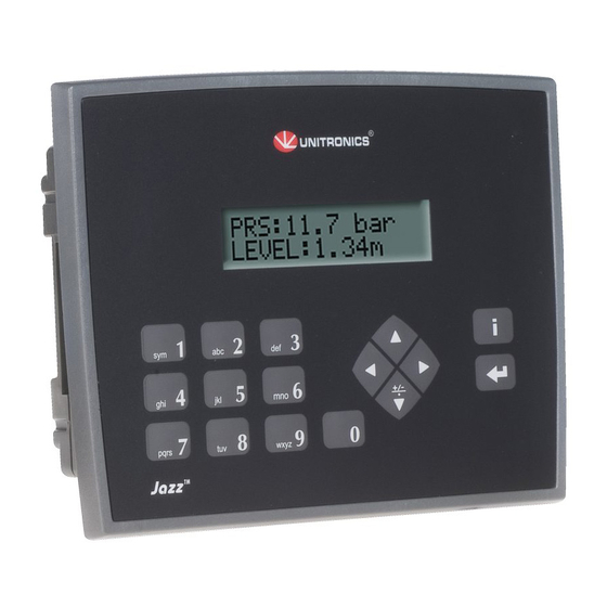
General Description
The products listed above are micro-PLC+HMIs, rugged programmable logic controllers that comprise
built-in operating panels.
Detailed Installation Guides containing the I/O wiring diagrams for these models, technical specifications,
and additional documentation are located in the Technical Library in the Unitronics website:
https://unitronicsplc.com/support-technical-library/
Alert Symbols and General Restrictions
When any of the following symbols appear, read the associated information carefully.
Symbol
Meaning
Danger
Warning
Caution
Caution
▪ Before using this product, the user must read and understand this document.
▪ All examples and diagrams are intended to aid understanding, and do not guarantee operation.
Unitronics accepts no responsibility for actual use of this product based on these examples.
▪ Please dispose of this product according to local and national standards and regulations.
▪ Only qualified service personnel should open this device or carry out repairs.
▪ Failure to comply with appropriate safety guidelines can cause severe injury or property
damage.
▪ Do not attempt to use this device with parameters that exceed permissible levels.
▪ To avoid damaging the system, do not connect/disconnect the device when power is on.
Environmental Considerations
▪ Do not install in areas with: excessive or conductive dust, corrosive or flammable gas,
moisture or rain, excessive heat, regular impact shocks or excessive vibration, in
accordance with the standards given in the product's technical specification sheet.
▪ Do not place in water or let water leak onto the unit.
▪ Do not allow debris to fall inside the unit during installation.
▪ Ventilation: 10mm space required between controller's top/bottom edges & enclosure walls.
▪ Install at maximum distance from high-voltage cables and power equipment.
Unitronics
▪
9 Digital Inputs including one HSC, 2 Analog/Digital
inputs, 2 Analog Inputs, 2 PT100/TC,5 Relay Outputs, 2
Transistor Outputs, 2 Analog Outputs
▪
9 Digital Inputs including one HSC, 2 Analog/Digital
Inputs, 1 Analog Input ,1 PT100/TC , 5 Relay Outputs, 2
Transistor Outputs
Description
The identified danger causes physical and property damage.
The identified danger could cause physical and property damage.
Use caution.
User Guide
1
Advertisement

Related Manuals for Unitronics Jazz JZ20-UA24


Summary of Contents for Unitronics Jazz JZ20-UA24
- Page 1 ▪ All examples and diagrams are intended to aid understanding, and do not guarantee operation. Unitronics accepts no responsibility for actual use of this product based on these examples. ▪ Please dispose of this product according to local and national standards and regulations.
-
Page 2: View Area
Add-on: during installation Add-on: after installation USB Port Installing an Add-on module requires sufficient clearance space 72 mm (2.835") DIN-rail mounting Panel mounting Snap PLC onto the DIN rail Note: Removing the unit requires clearance space. Recommendation: approximately 40mm (1.58”) Unitronics... -
Page 3: Wiring Procedure
▪ Use a metal cabinet. ▪ Connect the 0V and functional ground points (if exist) directly to the earth ground of the system. ▪ Use the shortest, less than 1m (3.3 ft.) and thickest, 2.08mm² (14AWG) min, wires possible. Unitronics... - Page 4 Installation Guide UL Compliance The following section is relevant to Unitronics’ products that are listed with the UL. The following models: JZ20-R10,JZ20-J-R10,JZ20-R16,JZ20-J-R16,JZ20-J-R16HS, JZ20-R31, JZ20-J-R31,JZ20-J-R31L,JZ20-T10,JZ20-J-T10,JZ20-T18,JZ20-J-T18,JZ20-J-T20HS,JZ20-T40, JZ20-J-T40,JZ20-UA24, JZ20-J-UA24, JZ20-UN20,JZ20-J-UN20, JZ20-J-ZK2. are UL listed for Ordinary Location. UL Ordinary Location In order to meet the UL ordinary location standard, panel-mount this device on the flat surface of Type 1...
- Page 5 Note the other as pnp, or wire both groups as npn, or as pnp. In either case, the npn/pnp pins must be connected. Input wiring, npn (sink) Input wiring, pnp (source) Input wiring (I0-I8), pnp (source), (I9-I10), npn (sink) Unitronics...
- Page 6 T+ as positive. (-328 to 3214˚F) -Red -Blue 0 to 1768˚C +Black +White (32 to 3214˚F) -Red -Blue 0 to 1768˚C +Black +White (32 to 3214˚F -Red -Blue -200 to 400˚C +Blue +White (-328 to 752˚F) -Red -Blue Unitronics...
- Page 7 ▪ PT100 (Sensor 1): use both inputs related to CM signal ▪ 4 wire PT100 can be used by leaving one of the sensor leads unconnected. JZ20-UA24/JZ20-J-UA24 Digital Outputs, Outputs’ Power Supply PNP Outputs +VO is the power supply input for pnp outputs O5–O6. Relay Outputs Unitronics...
- Page 8 To increase the life span of your contacts & protect the unit from potential damage by reverse-EMF, connect: ▪ A clamping diode in parallel with each inductive DC load ▪ An RC snubber circuit in parallel with each inductive AC load Analog Outputs Current/voltage connections Unitronics...
- Page 9 Note the other as pnp, or wire both groups as npn, or as pnp. In either case, the npn/pnp pins must be connected. Input wiring, npn (sink) Input wiring, pnp (source) Input wiring (I0-I8), pnp (source), (I9-I10), npn (sink) Unitronics...
- Page 10 -200 to 1300˚C +Orange +Orange (-328 to 3214˚F) -Red -Blue 0 to 1768˚C +Black +White (32 to 3214˚F) -Red -Blue 0 to 1768˚C +Black +White (32 to 3214˚F -Red -Blue -200 to 400˚C +Blue +White (-328 to 752˚F) -Red -Blue Unitronics...
- Page 11 To increase the life span of your contacts and protect the unit from potential damage by reverse- EMF, connect: ▪ A clamping diode in parallel with each inductive DC load ▪ An RC snubber circuit in parallel with each inductive AC load Unitronics...
-
Page 12: Technical Specifications
I9 & I10 may be wired as npn, pnp, or 0-10V analog inputs. one input may be wired as pnp, while the other is wired as analog. If one input is wired as npn, the other may not be wired as analog. Unitronics... - Page 13 Resolution (except 4-20mA) 10-bit (0 to 1023) or 12-bit (0-4095) - via software Resolution (at 4-20mA) 204 to 1023 (820 units) or 819 to 4095 (3277 units) - via software Conversion time 20mSec per channel, Synchronized to cycle time Unitronics...
- Page 14 The device can also measure voltage within the range of -5 to 56mV, at a resolution of 0.01mV. The device can also measure raw value frequency at a resolution of 14-bits (16384). Input ranges are shown in the following table: Unitronics...
- Page 15 A complete set of blank slides is available by separate order. Program Ladder code memory 48K (virtual) Execution time 1.5 µSec for bit operations (typical) Memory bits (coils) Memory integers (registers), 16 bit Timers HMI displays 60 user-designed displays available Unitronics...
- Page 16 - to communicate with other devices (including modems/GSM) - for RS485 networking. 15. Add-on module MJ20-ET1 enables communication over 100 Mbit/s TCP/IP network: Programming/data exchange with Unitronics software; Data exchange via MODBUS TCP as Master or Slave. Miscellaneous Clock (RTC) Real-time clock functions (date and time).
- Page 17 DIN-rail mounting The information in this document reflects products at the date of printing. Unitronics reserves the right, subject to all applicable laws, at any time, at its sole discretion, and without notice, to discontinue or change the features, designs, materials and other specifications of its products, and to either permanently or temporarily withdraw any of the forgoing from the market.
Need help?
Do you have a question about the Jazz JZ20-UA24 and is the answer not in the manual?
Questions and answers