Advertisement
Quick Links
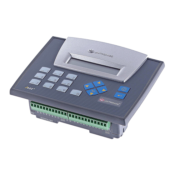
JZ10-11-T40
Before using this product, the user must read and understand this document.
For additional information regarding this product, refer to the user guide and technical specifications.
All examples and diagrams are intended to aid understanding, and do not guarantee operation.
Unitronics accepts no responsibility for actual use of this product based on these examples.
Please dispose of this product according to local and national standards and regulations.
Only qualified service personnel should open this device or carry out repairs.
Failure to comply with appropriate safety guidelines can cause severe injury or property damage.
Do not attempt to use this device with parameters that exceed permissible levels.
To avoid damaging the system, do not connect/disconnect the device when power is on.
Environmental Considerations
Do not install in areas with: excessive or conductive dust, corrosive or flammable gas,
moisture or rain, excessive heat, regular impact shocks or excessive vibration.
Ventilation: 10mm space required between the controller's top/bottom edges & enclosure walls.
Do not place in water or let water leak onto the unit.
Do not allow debris to fall inside the unit during installation.
Mounting
Dimensions
147.5 mm (5.807")
Add-on modules
Note: Installing an add-on module requires space.
During installation
72 mm (2.835")
Unitronics
Jazz™ Micro-OPLC™ Installation Guide
16 Digital, 2 Analog/Digital, 2 Analog Inputs, 20
Transistor Outputs
12 mm (0.472")
46.6 mm (1.835")
After installation
27.5 mm
(1.083")
113.7 mm (4.476")
13.2 mm (0.52")
Panel mounting
- Cut-out:
117 x 89mm (WxH) 4.606"x 3.504"
- Hold bracket against unit while
tightening screw
Panel
5mm (max)
0.197" (max)
Bracket
Gasket
16.8 mm (0.661")
1
Advertisement

Subscribe to Our Youtube Channel
Related Manuals for Unitronics Jazz Micro-OPLC JZ10-11-T40


Summary of Contents for Unitronics Jazz Micro-OPLC JZ10-11-T40
- Page 1 All examples and diagrams are intended to aid understanding, and do not guarantee operation. Unitronics accepts no responsibility for actual use of this product based on these examples. Please dispose of this product according to local and national standards and regulations.
- Page 2 In addition, 1 input may be wired as a pnp input, while the other is wired as an analog input. Note that if 1 input is wired as an npn input, the other may not be wired as an analog input. AN0 and AN1 are analog (current) inputs that may be wired using 2, 3, or 4 wires. Unitronics...
- Page 3 24VDC Input wiring (I0-I15), pnp (source), I16-I17, npn (sink) 24VDC +V 0V 24VDC Digital Outputs, Outputs’ Power Supply +V01 is the power supply for outputs O0–O11. +V02 is the power supply for outputs O12 –O19. +VO1 +VO2 24VDC 24VDC Unitronics...
- Page 4 JZ10-11-T40 Analog Inputs Note: Shields should be connected at the signal source. Analog Input wiring, current, 2 or 3-wire, Analog Input wiring, current, 4-wire, AN0 and AN1 AN0 and AN1 3 wire current transmitter 24VDC 4 wire 24VDC current transmitter 2 wire Power current...
Need help?
Do you have a question about the Jazz Micro-OPLC JZ10-11-T40 and is the answer not in the manual?
Questions and answers