Table of Contents
Advertisement
Quick Links
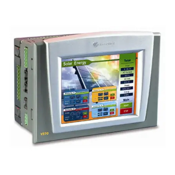
Vision™ OPLC™
This guide provides basic information for Unitronics' controller V570-57-T34. The V570-57-T34 offers
the following onboard I/Os via HE-10 connectors:
16 isolated Digital Inputs, configurable via wiring to include2 HSC/Shaft-encoder Inputs
2 Analog Inputs
16 isolated Transistor Outputs
Note that you cannot wire HE-10 I/Os directly into the PLC. HE-10 connector cables. DIN-rail
connector units are available by separate order. Check the Accessories section in the V570-57-T34
technical specifications for additional information.
Using your own cable, you can also connect the PLC I/Os directly to your machine.
General Description
V570 OPLCs are programmable logic controllers that comprise a built-in operating panel containing a
5.7" Color Touchscreen which displays a virtual keyboard when the application requires the operator
to enter data. Some models also offer an on-board I/O configuration.
Communications
I/O Options
Information Mode
Programming
Software,
& Utilities
Unitronics
2 isolated RS232/RS485 ports
Isolated CANbus port
The user may order and install an Ethernet port
Communication Function Blocks include: SMS, GPRS, MODBUS
serial/IP. Protocol FB enables PLC to communicate with almost
any external device, via serial or Ethernet communications
V570 supports digital, high-speed,
analog, weight and temperature
measurement I/Os via:
On-board I/O configuration
Model-dependent
Snap-in I/O Modules
Plug into the back of the
controller to provide an on-board
I/O configuration
I/O Expansion Modules
Local or remote I/Os may be added
via expansion port or CANbus.
Installation instructions and other data may be found in the module's technical
specification sheet.
This mode enables you to:
View & Edit operand values, COM port settings, RTC and screen
contrast/brightness settings
Calibrate the touchscreen
Stop, initialize, and reset the PLC
To enter Information Mode, press the <i> button for several seconds.
The Unitronics Setup CD contains VisiLogic software and other utilities
VisiLogic
Easily configure hardware and write both HMI and Ladder control
applications; the Function Block library simplifies complex tasks
such as PID. Write your application, and then download it to the
controller via the programming cable included in the kit.
Utilities
Includes UniOPC server, Remote Access for remote programming
Installation Guide
V570-57-T34
1
Advertisement
Table of Contents

Subscribe to Our Youtube Channel
Related Manuals for Unitronics Vision OPLC V570-57-T34


Summary of Contents for Unitronics Vision OPLC V570-57-T34
- Page 1 Vision™ OPLC™ Installation Guide V570-57-T34 This guide provides basic information for Unitronics’ controller V570-57-T34. The V570-57-T34 offers the following onboard I/Os via HE-10 connectors: 16 isolated Digital Inputs, configurable via wiring to include2 HSC/Shaft-encoder Inputs 2 Analog Inputs ...
-
Page 2: Danger Symbols
All examples and diagrams are intended to aid understanding, and do not guarantee operation. Unitronics accepts no responsibility for actual use of this product based on these examples. Please dispose of this product according to local and national standards and regulations. -
Page 3: Inserting The Battery
Note that the LCD screen may have a single pixel that is permanently either black or white. Panel Mounting Before you begin, note that the mounting panel cannot be more than 5 mm thick. 1. Make a panel cut-out according to the dimensions in the figure to the right. Unitronics... - Page 4 To avoid damaging the wire, do not exceed a maximum torque of 0.5 N·m (5 kgf·cm). Do not use tin, solder, or any substance on stripped wire that might cause the wire strand Caution to break. Install at maximum distance from high-voltage cables and power equipment. Unitronics...
-
Page 5: Wiring Procedure
If inputs 160 & 162 is set as a high-speed counter (without reset), inputs 161 & 163 can function as normal digital inputs 2. Output functionality is as follows: All 15 (161-175) outputs are pnp outputs Output 160 is an npn - High Speed Output I/O Wiring (HE-10 connectors) I/O Configuration Unitronics... - Page 6 V570-57-T34 Installation Guide npn (sink) Input Wiring Input wiring HSC input wiring pnp (source) Input Wiring Input wiring HSC input wiring Unitronics...
- Page 7 Vision™ OPLC™ Shaft-encoder Analog Input Wiring Analog input wiring, current (2-wire) Unitronics...
-
Page 8: Power Supply
Do not connect either the ‘Neutral or ‘Line’ signal of the 110/220VAC to device’s 0V pin. In the event of voltage fluctuations or non-conformity to voltage power supply specifications, connect the device to a regulated power supply. Unitronics... -
Page 9: Communication Port
By factory default, the port is set to RS232, termination ON. Use RS232 to download programs from a PC, and to communicate with serial devices and applications, such as SCADA. Use RS485 to create a multi-drop network containing up to 32 devices. Unitronics... - Page 10 1. Locate the four buttons on the sides of the controller, two on either side. 2. Press the buttons and hold them down to open the locking mechanism. 3. Gently rock the module from side to side, easing the module from the controller. Unitronics...
- Page 11 1. Line the circular guidelines on the controller up with the guidelines on the Snap-in I/O Module as shown below. 2 Apply even pressure on all 4 corners until you hear a distinct ‘click’. The module is now installed. Check that all sides and corners are correctly aligned. Unitronics...
- Page 12 The information in this document reflects products at the date of printing. Unitronics reserves the right, subject to all applicable laws, at any time, at its sole discretion, and without notice, to discontinue or change the features, designs, materials and other specifications of its products, and to either permanently or temporarily withdraw any of the forgoing from the market.
Need help?
Do you have a question about the Vision OPLC V570-57-T34 and is the answer not in the manual?
Questions and answers