Table of Contents
Advertisement
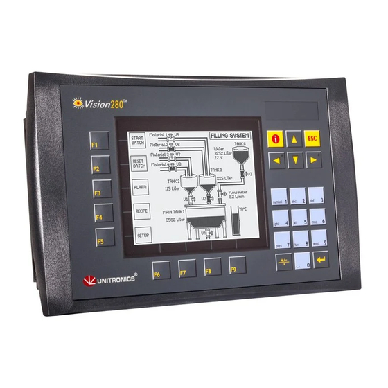
Vision™PLC+HMI
This guide provides basic information for Unitronics' Models V230/280/290 (Non-color Screens).
General Description
Vision PLC+HMIs are programmable logic controllers that comprise an integral operating panel
containing a graphic LCD screen and a keyboard. All models offer the same PLC features.
Operating panel features differ according to model.
V230
LCD + Keyboard
Communications
I/O Options
Information Mode
Programming
Software,
& Utilities
Unitronics
V280
Touchscreen + Keyboard
▪ 2 serial ports: RS232 (COM1), RS232/RS485 (COM2)
▪
1 CANbus port
▪ The user can order and install an additional port. Available port
types are: RS232/RS485, and Ethernet
▪
Communication Function Blocks include: SMS, GPRS, MODBUS
serial/IP Protocol FB enables PLC to communicate with almost
any external device, via serial or Ethernet communications
Vision supports digital, high-speed, analog, weight and temperature
measurement I/Os via:
▪ Snap-in I/O Modules
Plug into the back of the controller to provide an on-board I/O
configuration
▪
I/O Expansion Modules
Local or remote I/Os may be added via expansion port or CANbus
This mode enables you to:
▪ View & Edit operand values, COM port settings, RTC and screen
contrast/brightness settings
▪
Calibrate the touchscreen
▪ Stop, initialize, and reset the PLC
To enter Information Mode, press the <i> button for several seconds.
▪ VisiLogic
Easily configure hardware and write both HMI and Ladder control
applications; the Function Block library simplifies complex tasks
such as PID. Write your application, and then download it to the
controller via the programming cable included in the kit.
Note that in order to program the V290-19-B20B,you must select the
V280/V530 in VisiLogic's Hardware Configuration.
▪ Utilities
These include UniOPC server, Remote Access for remote
programming and diagnostics, and DataXport for run-time data logging
To learn how to use and program the controller, as well as use utilities such
as Remote Access, refer to the VisiLogic Help system.
User Guide
Models V230/280/290
V290
Touchscreen only
1
Advertisement
Table of Contents

Related Manuals for Unitronics Vision V280


Summary of Contents for Unitronics Vision V280
- Page 1 User Guide Vision™PLC+HMI Models V230/280/290 This guide provides basic information for Unitronics’ Models V230/280/290 (Non-color Screens). General Description Vision PLC+HMIs are programmable logic controllers that comprise an integral operating panel containing a graphic LCD screen and a keyboard. All models offer the same PLC features.
-
Page 2: Kit Contents
▪ All examples and diagrams are intended to aid understanding, and do not guarantee operation Unitronics accepts no responsibility for actual use of this product based on these examples ▪ Please dispose of this product according to local and national standards and regulations ▪... - Page 3 Class I, Division 2, Groups A, B, C and D These Release Notes relate to all Unitronics products that bear the UL symbols used to mark products that have been approved for use in hazardous locations, Class I, Division 2, Groups A, B, C and D.
- Page 4 à risques, Class I, Division 2, Groups A, B, C et D. Cette note fait référence à tous les produits Unitronics portant le symbole UL - produits qui ont été certifiés pour une utilisation dans des endroits dangereux, Classe I, Division 2, Groupes A, B, C et D.
- Page 5 User Guide Mounting Dimensions V230 V280 Unitronics...
- Page 6 ▪ The mounting panel cannot be more than 5 mm thick ▪ To minimize electromagnetic interference, mount the controller on a metal panel and earth the power supply according to the details on page 6. Make a panel cut-out that suits your model controller. V230 Cut-out Dimensions Unitronics...
- Page 7 User Guide V280 Cut-out Dimensions V290 Cut-out Dimensions ▪ The necessary torque is 0.45 N·m (4.5 kgf·cm). Caution Unitronics...
-
Page 8: Wiring: General
To avoid damaging the wire, do not exceed a maximum torque of 0.5 N·m (5 kgf·cm) Caution ▪ Do not use tin, solder, or any substance on stripped wire that might cause the wire strand to break –2.08 mm Use crimp terminals for wiring; use 26-14 AWG wire (0.13 mm Unitronics... -
Page 9: Power Supply
Install an external circuit breaker. Guard against short- circuiting in external wiring ▪ Double-check all wiring before turning on the power supply In the event of voltage fluctuations or non-conformity to voltage power supply specifications, connect the device to a regulated power supply Unitronics... -
Page 10: Communication Ports
▪ Before you begin, touch a grounded object to discharge any electrostatic charge 1. Before removing a Snap-in I/O Module or opening the controller, you must turn off the power Unitronics... - Page 11 1. Line the circular guidelines on the controller up with the guidelines on the Snap-in I/O Module as shown below. 2 Apply even pressure on all 4 corners until you hear a distinct ‘click’. The module is now installed. Check that all sides and corners are correctly aligned. Unitronics...
- Page 12 CAN protocols: Circuit protection ▪ CANopen: 127 controllers or external device devices ▪ Unitronics’ proprietary UniCAN: 60 terminating resistor controllers, (512 data bytes per scan) The CANbus port is galvanically isolated. CANbus Wiring Use twisted-pair cable. DeviceNet® thick shielded twisted pair cable is recommended.
-
Page 13: Technical Specifications
User Guide Technical Specifications This guide provides specifications for Unitronics’ models V230-13-B20B,V280-18-B20B, V290-19-B20B. You can find additional information in the Technical Library at www.unitronics.com. Technical Specifications Power Supply Input voltage 12VDC or 24VDC Permissible range 10.2VDC to 28.8VDC with less than 10% ripple Max. - Page 14 Up to 32 Cable type Shielded twisted pair, in compliance with EIA RS485 Cable length Up to 1200m (4000′) CANbus port Unitronics’ CANbus protocols Nodes CANopen Power requirements 24VDC (±4%), 40mA max. per unit Galvanic isolation Yes, between CANbus and controller...
- Page 15 5% to 95% (non-condensing) The information in this document reflects products at the date of printing. Unitronics reserves the right, subject to all applicable laws, at any time, at its sole discretion, and without notice, to discontinue or change the features, designs, materials and other specifications of its products, and to either permanently or temporarily withdraw any of the forgoing from the market.
Need help?
Do you have a question about the Vision V280 and is the answer not in the manual?
Questions and answers
Как приобрести руководство по программированию V280