Table of Contents
Advertisement
Quick Links
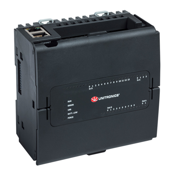
UniStream
PLC
This guide provides basic installation information for specific UniStream
built-in I/O. Technical specifications may be downloaded from the Unitronics website.
General Features
Unitronics' UniStream
with a built-in I/O configuration.
The series is available in three versions: Pro, Standard, and Basic.
Note that a model number that includes:
•
B10/C10 refers to Pro version (e.g. USC-B10-T24)
•
B5/C5 refers to Standard version (e.g. USC-B5-RA28)
•
B3/B3 refers to Basic version (e.g. only for USC-B3-T20)
Page 2 contains a comparison table detailing the features offered by the different models.
Exact features are detailed in the product specification sheets.
Power
Features
COM
Options
COM
Protocols
Programming
Software
HMI
Unitronics
®
®
PLCs are DIN-rail mounted Programmable Logic Controllers (PLCs)
▪ Built-in Trends and Gauges, auto-tuned PID, data tables, data
sampling, and Recipes
▪ UniApps™: Access & edit data, monitor, troubleshoot & debug
and more
▪ Security: Multi-level password protection
▪ Alarms: Built-in system, ANSI/ISA standards
▪ Built-in ports: 2 Ethernet, 1 USB host, 1 USB device port
▪ Add-on ports (UAC-CB), available by separate order:
➢ 1 CANbus port may be added to all models
➢ RS232/485 ports: according to model technical specifications
▪ Fieldbus: CANopen, CAN Layer2, MODBUS, EtherNetIP and
more. Implement any serial RS232/485, TCP/IP, or CANbus
third-party protocols via Message Composer
▪ Advanced: SNMP Agent/Trap, e-mail, SMS, modems,
GPRS/GSM, FTP Server/Client, Web Server, SQL, and MQTT.
▪ Remote Access via any device that supports VNC.
All-in-One UniLogic software for hardware configuration,
communications, PLC and HMI applications; free download.
All UniStream
®
PLCs can display HMI screens on the following devices:
•
UniStream Display (USL)
•
UniStream Modular HMI panel (USP)
•
UniStream Built-in (on the panels integral to the device)
•
Any device screen that supports VNC
Installation Guide
USC-B5-B1, USC-B10-B1,
USC-C5-B1, USC-C10-B1,
USC-B5-TR22, USC-B10-TR22,
USC-C5-TR22, USC-C10-TR22,
USC-B5-T24, USC-B10-T24,
USC-C5-T24, USC-C10-T24
®
PLC models with
1
Advertisement
Table of Contents

Related Manuals for Unitronics UniStream USC-B5-B1


Summary of Contents for Unitronics UniStream USC-B5-B1
- Page 1 USC-B5-T24, USC-B10-T24, USC-C5-T24, USC-C10-T24 This guide provides basic installation information for specific UniStream ® PLC models with built-in I/O. Technical specifications may be downloaded from the Unitronics website. General Features Unitronics’ UniStream ® PLCs are DIN-rail mounted Programmable Logic Controllers (PLCs) with a built-in I/O configuration.
- Page 2 USB device (programming No** port) * Note that B3/C3 models do not support features requiring SD cards. In addition, Alarm History is not retained after PLC reset. ** Note that B3/C3 models may be programmed only via Ethernet cable. Unitronics...
-
Page 3: Before You Begin
Use caution. ▪ All examples and diagrams are intended to aid understanding, and do not guarantee operation. Unitronics accepts no responsibility for actual use of this product based on these examples. ▪ Please dispose of this product according to local and national standards and regulations. -
Page 4: Kit Contents
(Not shown) Connection point for connector Uni-I/O™ modules and I/O expansion adapters, shipped covered. Leave covered when not in use. CONFIRM Used to implement and confirm USB Actions. Button USB Host Provides the interface for port external USB devices. Unitronics... -
Page 5: Mechanical Dimensions
▪ Any modules that will be installed; ensure you allow space to install/uninstall modules Module dimensions and installation instructions are in the modules’ specifications. For exact dimensions, please refer to the Mechanical Dimensions shown below Mechanical Dimensions Front View Bottom View Unitronics... - Page 6 ▪ Note that disconnecting the battery halts the preservation of back-up values and causes them to be deleted. 1. Open the bottom and inner doors. If there is a battery present, remove it. 3. Slide the battery into place. Unitronics...
- Page 7 1. Strip the wire to a length of 7±0.5mm (0.250–0.300 inches). 2. Unscrew the terminal to its widest position before inserting a wire. 3. Insert the wire completely into the terminal to ensure a proper connection. 4. Tighten enough to keep the wire from pulling free. Unitronics...
- Page 8 ➢ Keep shield connections as short as possible. ➢ Ensure shield continuity when extending shielded cables. For detailed information, refer to the document System Wiring Guidelines, located in the Technical Library in the Unitronics’ website. Wiring the Power Supply The controller requires an external power supply.
- Page 9 ▪ Each input offers two modes: voltage or current. You can set each input independently. ▪ The mode is determined by the hardware configuration within the software application. ▪ Note that if, for example, you wire the input to current, you must also set it to current in the software application. Unitronics...
- Page 10 ▪ To avoid risk of fire or property damage, always use a limited current source or connect a current limiting device in series with the relay contacts The relay outputs are arranged in two isolated groups: O0-O3 share the common return CM2. O4-O7 share the common return CM3. Unitronics...
- Page 11 CM4 to the system 0V. ▪ Do not use point CM4 for any purpose other than connecting the digital output load. Using it for any other purpose may damage the controller. Normal Transistor Output High Speed PWM Output Unitronics...
- Page 12 The information in this document reflects products at the date of printing. Unitronics reserves the right, subject to all applicable laws, at any time, at its sole discretion, and without notice, to discontinue or change the features, designs, materials and other specifications of its products, and to either permanently or temporarily withdraw any of the forgoing from the market.
Need help?
Do you have a question about the UniStream USC-B5-B1 and is the answer not in the manual?
Questions and answers