Table of Contents
Advertisement
Quick Links
Vision™ OPLC™
This guide provides basic information for Unitronics' Vision120™.
General Description
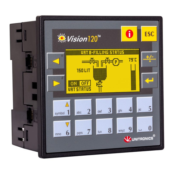
V120 OPLCs are micro-OPLCs, rugged programmable logic
controllers that comprise an:
On-board I/O configuration
Built-in operating panel containing a graphic LCD
screen and a keypad
Communications
I/O Options
Programming
The Vision120 User Guide and the product's technical specification sheet contain additional
information. These documents are located on the Unitronics' Setup CD. They may also be
downloaded from the Technical Library at www.unitronics.com.
Standard Kit Contents
V120 controller
Mounting brackets (x2)
I/O connectors (x2)
5-pin CANbus connector and CANbus network termination resistor (CANbus models)
Unitronics
All V120 controllers comprise 2
RS232/485 ports
Certain models comprise a
Canbus port
On-board I/O configuration
Model-dependent; may include
digital, high-speed, and
analog I/Os
I/O Expansion Modules
Via I/O expansion port adapter,
connect up to 128 additional I/Os
per controller
Write both the HMI and Ladder control application using VisiLogic freeware.
Installation Guide
Vision120™
Programming cable + RS232 adapter
Rubber seal (mounted in back of panel)
Unitronics' Setup CD
1
Advertisement
Table of Contents

Related Manuals for Unitronics Vision120


Summary of Contents for Unitronics Vision120
- Page 1 Write both the HMI and Ladder control application using VisiLogic freeware. The Vision120 User Guide and the product’s technical specification sheet contain additional information. These documents are located on the Unitronics’ Setup CD. They may also be downloaded from the Technical Library at www.unitronics.com.
- Page 2 All examples and diagrams are intended to aid understanding, and do not guarantee operation. Unitronics accepts no responsibility for actual use of this product based on these examples. Please dispose of this product according to local and national standards and regulations.
- Page 3 4. Tighten the bracket screws against the panel. Hold the bracket securely against the unit while tightening the screw. 5. When properly mounted, the controller is squarely situated in the panel cut-out as shown in the figure to the right. Unitronics...
- Page 4 10/06 Vision™ OPLC™ Vision120™ DIN-rail mounting 1. Snap the controller onto the DIN rail as shown in the figure to the right. 2. When properly mounted, the controller is squarely situated on the DIN-rail as shown in the figure to the right.
- Page 5 A signal (+) 0V reference (RS232 signal) TXD signal (RS232 signal) Pin #1 RXD signal (RS232 signal) 0V reference (RS232 signal) DSR signal* B signal (-) *Standard programming cables do not provide connection points for pins 1 and 6. Unitronics...
- Page 6 10/06 Vision™ OPLC™ Vision120™ RS232 to RS485: Changing Jumper Settings Ports can be set to either RS232 or RS485 according to jumper settings. To access the jumpers, you must open the controller, and then remove the module’s PCB board. Before you begin, turn off the power supply, disconnect and dismount the controller.
- Page 7 7. Close the controller by snapping the plastic cover back in its place. If the card is placed correctly, the cover will snap on easily. RS232/RS485 Jumper Settings Jumper Settings RS485 Termination Jumper RS232* RS485 Jumper COM 1 COM 2 *Default factory setting. Unitronics...
- Page 8 The information in this document reflects products at the date of printing. Unitronics reserves the right, subject to all applicable laws, at any time, at its sole discretion, and without notice, to discontinue or change the features, designs, materials and other specifications of its products, and to either permanently or temporarily withdraw any of the forgoing from the market.
Need help?
Do you have a question about the Vision120 and is the answer not in the manual?
Questions and answers