Table of Contents
Advertisement
Quick Links
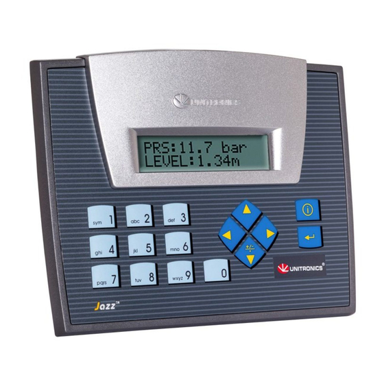
Jazz™PLC+HMI
JZ20-UN20/JZ20-J-UN20
Before using this product, the user must read and understand this document.
For additional information regarding this product, refer to the user guide and technical specifications.
All examples and diagrams are intended to aid understanding, and do not guarantee operation.
Unitronics accepts no responsibility for actual use of this product based on these examples.
Please dispose of this product according to local and national standards and regulations.
Only qualified service personnel should open this device or carry out repairs.
Failure to comply with appropriate safety guidelines can cause severe injury or property damage.
Do not attempt to use this device with parameters that exceed permissible levels.
To avoid damaging the system, do not connect/disconnect the device when power is on.
Environmental Considerations
Do not install in areas with: excessive or conductive dust, corrosive or flammable gas,
moisture or rain, excessive heat, regular impact shocks or excessive vibration.
Ventilation: 10mm space required between the PLC+HMIs' top/bottom edges & enclosure
walls.
Do not place in water or let water leak onto the unit.
Do not allow debris to fall inside the unit during installation.
Mounting
Dimensions
* Note that for JZ20-J modules those dimensions are 7.5 mm (0.295").
Unitronics
Micro-PLC+HMI Installation Guide
9 Digital Inputs, 2 Analog/Digital Inputs, 1 Analog Input
1 PT100/TC , 5 Relay Outputs, 2 PNP Outputs
1
Advertisement
Table of Contents

Related Manuals for Unitronics Jazz JZ20-J-UN20


Summary of Contents for Unitronics Jazz JZ20-J-UN20
- Page 1 All examples and diagrams are intended to aid understanding, and do not guarantee operation. Unitronics accepts no responsibility for actual use of this product based on these examples. Please dispose of this product according to local and national standards and regulations.
- Page 2 To avoid damaging the wire, use a maximum torque of 0.5 N·m (5 kgf·cm). Do not use tin, solder, or any substance on stripped wire that might cause the wire Caution strand to break. Install at maximum distance from high-voltage cables and power equipment. Unitronics...
- Page 3 Note that if 1 input is wired as an npn input, the other may not be wired as an analog input. AN1 is an analog (current) input that may be wired using 2, 3, or 4 wires. Analog Input 0 can function as either thermocouple or PT100 input. Unitronics...
- Page 4 Analog Inputs Note: Shields should be connected at the signal source. Analog Input wiring, current, 2 wire, AN1 Analog Input wiring, current, 3 wire, AN1 Analog Input wiring, voltage, AN2 and AN3 Analog Input wiring, current, 4 wire, AN1 Unitronics...
- Page 5 0 to 1768˚C +Black +White (32 to 3214˚F) -Red -Blue 0 to 1768˚C +Black +White (32 to 3214˚F -Red -Blue -200 to 400˚C +Blue +White (-328 to 752˚F) -Red -Blue PT100 (Sensor 0): use both inputs related to CM signal Unitronics...
- Page 6 An RC snubber circuit in parallel with each inductive AC load The information in this document reflects products at the date of printing. Unitronics reserves the right, subject to all applicable laws, at any time, at its sole discretion, and without notice, to discontinue or change the features, designs, materials and other specifications of its products, and to either permanently or temporarily withdraw any of the forgoing from the market.
Need help?
Do you have a question about the Jazz JZ20-J-UN20 and is the answer not in the manual?
Questions and answers