Table of Contents
Advertisement
Quick Links
Advertisement
Table of Contents

Related Manuals for Arbor Technology Qseven EmQ-i2205


Summary of Contents for Arbor Technology Qseven EmQ-i2205
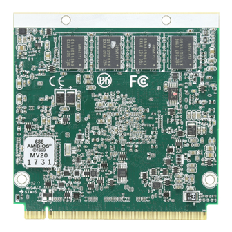
- Page 1 EmQ-i2205 Qseven® CPU Module User’s Manual Version 1.0 2017.08...
- Page 2 This page is intentionally left blank. - II -...
- Page 3 Revision History Version Release Time Description 2017.08 Initial release - i -...
-
Page 4: Table Of Contents
Contents Contents Revision History .................i Contents .....................ii Preface....................iv Copyright Notice ..................iv Declaration of Conformity ..............iv CE ....................iv FCC Class B ..................v RoHS ....................v SVHC / REACH ................vi Warning ....................vi Replacing the Lithium Battery ..............vi Technical Support .................. -
Page 5: Contents
Contents 3.2.11 USB Configuration ............. 30 3.3 Chipset ................... 32 3.3.1 North Bridge ................33 3.3.2 South Bridge ................. 35 3.4 Security ..................37 3.5 Boot ....................38 Appendices ..................41 Appendix A. I/O Port Address Map ............42 Appendix B. Interrupt Request Lines (IRQ) .......... 44 Appendix C. -
Page 6: Preface
Preface Preface Copyright Notice All Rights Reserved. The information in this document is subject to change without prior notice in order to improve the reliability, design and function. It does not represent a commitment on the part of the manufacturer. Under no circumstances will the manufacturer be liable for any direct, indirect, special, incidental, or consequential damages arising from the use or inability to use the product or documentation, even if advised of the possibility of such... -
Page 7: Fcc Class B
RoHS ARBOR Technology Corp. certifies that all components in its products are in compliance and conform to the European Union’s Restriction of Use of Haz- ardous Substances in Electrical and Electronic Equipment (RoHS) Directive 2002/95/EC. -
Page 8: Svhc / Reach
Preface SVHC / REACH To minimize the environmental impact and take more responsibility to the earth we live, Arbor hereby confirms all products comply with the restriction of SVHC (Substances of Very High Concern) in (EC) 1907/2006 (REACH --Registration, Evaluation, Authorization, and Restriction of Chemicals) regulated by the European Union. -
Page 9: Warranty
Preface Warranty This product is warranted to be in good working order for a period of two years from the date of purchase. Should this product fail to be in good working order at any time during this period, we will, at our option, replace or repair it at no additional charge except as set forth in the following terms. - Page 10 This page is intentionally left blank. - viii -...
-
Page 11: Chapter 1 Introduction
Chapter 1 Introduction Chapter 1 - Introduction - 1 -... -
Page 12: The Product
Introduction 1.1. The Product • Fanless Design • Soldered Onboard Intel Celeron N3000 family SoC processor ® • Integrated Gigabit Ethernet • 2 x DisplayPorts / 2 x eDP port • Extended Operating Temp.: -20 ~ 70ºC 1.2. About this Manual This manual is intended for experienced users and integrators with hardware knowledge of computers. -
Page 13: Specifications
Introduction 1.3. Specifications Form Factor Qseven CPU Module ® Soldered onboard Intel® Celeron N3060 2.48GHz Processor processor/N3160 2.24GHz processor Soldered onboard 2GB DDR3L SDRAM, upgradable to Memory BIOS AMI BIOS Serial Port 1 x UART port(TX/RX only) 4 x USB 2.0 ports USB 2.0 2 x USB3.0 SuperSpeed ports Serial ATA... -
Page 14: Inside The Package
Introduction 1.4. Inside the Package Before starting with the installation, make sure the following items are shipped. If any of the items is missing or appears damaged, contact your local dealer or distributor. 1 x EmQ-i2205 Qseven® CPU Module 1 x Driver CD 1 x Quick Installation Guide 1.5. -
Page 15: Driver Installation Note
Introduction 1.6. Driver Installation Note The CPU board supports Windows 8.1. Find the necessary drivers on the CD that comes with your purchase. For different OS, the driver/utility installation may vary slightly, but generally they are similar. Find the drivers on CD by the following paths: Windows 8.1 64-bit Driver Path... - Page 16 This page is intentionally left blank. - 6 -...
-
Page 17: Chapter 2 Board Overview
Chapter 2 Board Overview Chapter 2 - Board Overview - 7 -... -
Page 18: Board Dimensions
Board Overview 2.1. Board Dimensions 32,26 ø2,7 Unit:mm - 8 -... -
Page 19: Block Diagram
Board Overview 2.2. Block Diagram DDR3L-1600 MHz , up to 8GB Onboard DDR3L 2/ 4GB SDRAM 1 x eDP port 1 x DP port 1 x DP port 4 x USB 2.0 ports Intel ® 2 x USB SS ports Celeron N3060 3 x PCIex1... -
Page 20: Connector Pin Definition
Board Overview 2.3. Connector Pin Definition Pin Signal Pin Signal Pin Signal Pin Signal AZ_SDATA_IN0 SMB_CLK GBE_MDI3- GBE_MDI2- AZ_SDATA_OUT SMB_DAT GBE_MDI3+ GBE_MDI2+ THRM# WDTRIG# GBE_LINK100# GBE_LINK1000# THRMTRIP# WDOUT GBE_MDI1- GBE_MDI0- USB_SSTX0- USB_SSRX0- GBE_MDI1+ GBE_MDI0+ USB_SSTX0+ USB_SSRX0- LED_LINK# GBE_ACT# USB_6_7_OC# USB_4_5_ (N/C) SLP_S4# (N/C) - Page 21 Board Overview Pin Signal Pin Signal Pin Signal Pin Signal 131 DP_DDI2_TX3+ 132 STP23 197 GND 198 GND 133 DP_DDI2_TX3- 134 STP24 199 SPI_MOSI 200 SPI_CS0# 135 GND 136 GND 201 SPI_MISO 202 SPI_CS1# 137 DP_DDI2_TX1+ 138 DP_DDI2_AUX+ 203 SPI_SCK 204 MFG_NC4 (N/C) 139 DP_DDI2_TX1- 140 DP_DDI2_AUX-...
- Page 22 This page is intentionally left blank. - 12 -...
-
Page 23: Chapter 3 - Bios
Chapter 3 BIOS Chapter 3 - BIOS - 13 -... - Page 24 BIOS The BIOS Setup utility is featured by AMI BIOS to configure the system settings stored in the system’s BIOS ROM. AMI BIOS is activated once the computer powers on. After entering the utility, use the left/right arrow keys to navigate between the top menus and use the down arrow key to access one.
-
Page 25: Main
BIOS 3.1 Main The AMI BIOS provides a Setup utility program for specifying the system configurations and settings. The BIOS ROM of the system stores the Setup utility and configurations. When you turn on the computer, the AMI BIOS is immediately activated. - Page 26 BIOS Key Commands BIOS Setup Utility is mainly a key-based navigation interface. Please refer to the following key command instructions for navigation process. Keystroke Function Move to highlight a particular configuration screen from ◄ ► the top menu bar / Move to highlight items on the screen ▼...
-
Page 27: Advanced
BIOS 3.2 Advanced The “Advanced” setting page provides you the options to configure the details of your hardware. Aptio Setup Utility - Copyright (C) 2017 American Megatrends, Inc. Main Advanced Chipset Security Boot Save & Exit ACPI Settings System ACPI Parameters. F81866 Super IO Configuration Hardware Monitor S5 RTC Wake Settings... -
Page 28: Acpi Settings
BIOS 3.2.1 ACPI Settings Aptio Setup Utility - Copyright (C) 2012 American Megatrends, Inc. Aptio Setup Utility - Copyright (C) 2016 American Megatrends, Inc. Advanced ACPI Settings Enables or Disables System ability to Enable Hibernation [Enabled] hibernate (OS/S4 Sleep ACPI Sleep State State). -
Page 29: F81866 Super Io Configuration
BIOS 3.2.2 F81866 Super IO Configuration Aptio Setup Utility - Copyright (C) 2012 American Megatrends, Inc. Aptio Setup Utility - Copyright (C) 2017 American Megatrends, Inc. Advanced F81866 Super IO Configuration Set Parameters of Serial Port 1 (COMA) Super IO Chip F81866 ►... -
Page 30: Hardware Monitor
BIOS 3.2.3 Hardware Monitor Aptio Setup Utility - Copyright (C) 2012 American Megatrends, Inc. Aptio Setup Utility - Copyright (C) 2017 American Megatrends, Inc. Advanced Pc Health Status CPU Temperature : +50˚C System Temperature : +43˚C Fan1 Speed : N/A +3.3S : +3.344 V +V5A... -
Page 31: S5 Rtc Wake Settings
BIOS 3.2.4 S5 RTC Wake Settings Aptio Setup Utility - Copyright (C) 2016 American Megatrends, Inc. Advanced Enables or disables [Disabled] Wake system from S5 system wake on alarm event. When enabled, system will wake on the hr::min::sec specified. Select Dynamic Time, System will wake on the current time... - Page 32 BIOS Sets if to awake the system at a defined moment. Defines the (hour) time to wake the Wake up system. hour ► 0 to 23 configurable. Wake System with Defines the (minute) time to wake the Wake up Fixed Time system.
-
Page 33: Cpu Configuration
BIOS 3.2.5 CPU Configuration Access this submenu to configure the CPU features. Aptio Setup Utility - Copyright (C) 2017 American Megatrends, Inc. Advanced CPU Configuration Socket specific CPU Information Socket 0 CPU Information CPU Speed 1600 MHz 64-bit Supported Limit CPUID Maximum [Disabled] →←: Select Screen ↓↑: Select Item... -
Page 34: Ppm Configuration
BIOS 3.2.6 PPM Configuration Access this submenu to setup the PPM Configuration. Aptio Setup Utility - Copyright (C) 2017 American Megatrends, Inc. Advanced Enable/Disabled Intel PPM Configuration Speedstep EIST [Enabled] CPU C state report [Enabled] →←: Select Screen ↓↑: Select Item Enter: Select +/-: Change Opt. -
Page 35: Sata Configuration
BIOS 3.2.7 SATA Configuration Aptio Setup Utility - Copyright (C) 2012 American Megatrends, Inc. Aptio Setup Utility - Copyright (C) 2017 American Megatrends, Inc. Advanced SATA Configuration Enable/Disable SATA Device. SATA Controller [Enabled] SATA Interface Speed [Gen3] SATA Port0 Not Present Port 0 [Enabled] SATA Port1... -
Page 36: Lpss & Scc Configuration
BIOS 3.2.8 LPSS & SCC Configuration Aptio Setup Utility - Copyright (C) 2017 American Megatrends, Inc. Advanced LPSS Configuration SCC SD Card Support LPSS I2C #1(D24: F1) [ACPI Mode] Enable\Disable. Runtime D3 Support [Enabled] →←: Select Screen ↓↑: Select Item Enter: Select +/-: Change Opt. -
Page 37: Csm Configuration
BIOS 3.2.9 CSM Configuration Aptio Setup Utility - Copyright (C) 2012 American Megatrends, Inc. Aptio Setup Utility - Copyright (C) 2017 American Megatrends, Inc. Advanced Compatibility Support Module Configuration Enable/Disable CSM Support. CSM Support [Enabled] CSM16 Module Version 07.79 Boot option filter [UEFI and Legacy] Option ROM execution Network... - Page 38 BIOS Set the OpROM execution policy for devices other than Network, Storage, or Video. Other PCI device Options: Do not launch, UEFI and Legacy ► (default) - 28 -...
-
Page 39: Sdio Configuration
BIOS 3.2.10 SDIO Configuration Aptio Setup Utility - Copyright (C) 2017 American Megatrends, Inc. Advanced SDIO Configuration SCC SD Card Support Enable\Disable. SDIO Access Mode [Auto] →←: Select Screen ↓↑: Select Item Enter: Select +/-: Change Opt. F1: General Help F2: Previous Values F9: Optimized Defaults F10: Save &... -
Page 40: Usb Configuration
BIOS 3.2.11 USB Configuration Aptio Setup Utility - Copyright (C) 2017 American Megatrends, Inc. Main Advanced Chipset Boot Security Save & Exit USB Configuration Enables Legacy USB support. AUTO option disables legacy USB Module Version support if no USB devices are connected. - Page 41 BIOS The time-out value for Control, Bulk and Interrupt USB transfer time-out transfers. Options: 1/5/10/20 sec (default) USB mass storage device Start Unit command Device reset time-out time-out. Options: 10/20 (default)/30/40 sec Maximum time the device will take before it properly reports itself to the Host Controller.
-
Page 42: Chipset
BIOS 3.3 Chipset Aptio Setup Utility - Copyright (C) 2017 American Megatrends, Inc. Main Advanced Security Boot Save & Exit Chipset North Bridge ► North Bridge Parameters ► South Bridge →←: Select Screen ↓↑: Select Item Enter: Select +/-: Change Opt. F1: General Help F2: Previous Values F9: Optimized Defaults... -
Page 43: North Bridge
BIOS 3.3.1 North Bridge Aptio Setup Utility - Copyright (C) 2017 American Megatrends, Inc. Chipset Intel IGD Configuration Config Intel IGD LCD Control Settings. Memory Information Total Memory 4096 MB (LPDDR3) →←: Select Screen ↓↑: Select Item Enter: Select +/-: Change Opt. F1: General Help F2: Previous Values F9: Optimized Defaults... - Page 44 BIOS 3.3.1.1 Intel IGD Configuration Setting Description Enable / Disable GOP Driver. Enable GOP driver will GOP Driver unload VBIOS; disable it will load VBIOS. Enabled is the default. ► Enable / Disable Integrated Graphics Device (IGD). Enabled (default): Enable IGD when selected as ►...
-
Page 45: South Bridge
BIOS 3.3.2 South Bridge Aptio Setup Utility - Copyright (C) 2017 American Megatrends, Inc. Chipset Azalia Configuration Azalia HD Audio USB Configuration Options PCI Express Configuration →←: Select Screen ↓↑: Select Item Enter: Select +/-: Change Opt. F1: General Help F2: Previous Values F9: Optimized Defaults F10: Save and Exit... - Page 46 BIOS 3.3.2.1 SB HD Azalia Configuration Item Description Control detection of the Azalia deivce Disabled: Azalia will be unconditionally disabled. ► Audio Controller Enabled (default): Azalia will be unconditionally ► enabled. 3.3.2.2 USB Configuration Item Description Enable (default) or Disable XHCI Mode (Mode of XHCI Mode operaton of xHCI controller).
-
Page 47: Security
BIOS 3.4 Security The Security menu sets up the administrator password. Aptio Setup Utility - Copyright (C) 2017 American Megatrends, Inc. Main Advanced Chipset Security Save & Exit Boot Set Administrator Password Description Password Minimum length Maximum length Administrator Password →←: Select Screen ↓↑: Select Item Enter: Select... -
Page 48: Boot
BIOS 3.5 Boot Aptio Setup Utility - Copyright (C) 2017 American Megatrends, Inc. Main Advanced Chipset Security Save & Exit Boot Number of seconds to Boot Configuration wait for setup Setup Prompt Timeout activation key. Bootup NumLock State [On] 65535(0xFFFF) means Quiet Boot [Disabled] indefinite waiting. - Page 49 BIOS 3.6 Save & Exit Aptio Setup Utility - Copyright (C) 2017 American Megatrends, Inc. Main Advanced Chipset Security Boot Save & Exit Exit system setup Save Options after saving the Save Changes and Exit changes. Discard Changes and Exit Default Options Restore Defaults Lauch EFI Shell from filesystem device...
- Page 50 This page is intentionally left blank. - 40 -...
-
Page 51: Appendices
Appendices Appendices - 41 -... -
Page 52: Appendix A. I/O Port Address Map
Appendices Appendix A. I/O Port Address Map Each peripheral device in the system is assigned a set of I/O port addresses which also becomes the identity of the device. The following table lists the I/O port addresses used. Address Device Description 0x000003F8- Communications Port (CON1) 0x000003FF... - Page 53 Appendices Address Address Device Description Device Description 0x00000065- 0x000003C0- Motherboard resources Standard VGA Graphics Adapter 0x00000065 0x000003DF 0x00000067- 0x00000070- Motherboard resources System CMOS/real time clock 0x00000067 0x00000071 0x00000080- 0x00000040- Motherboard resources System timer 0x0000008F 0x00000043 0x00000092- 0x00000050- Motherboard resources System timer 0x00000092 0x00000053 0x000000B2-...
-
Page 54: Appendix B. Interrupt Request Lines (Irq)
Appendices Appendix B. Interrupt Request Lines (IRQ) Peripheral devices use interrupt request lines to notify CPU for the service required. The following table shows the IRQ used by the devices on board. Level Function IRQ0 System timer IRQ1 Standard PS/2 Keyboard IRQ3 Communications Port (COM1) IRQ4... -
Page 55: Appendix C. Bios Memory Map
Appendices Appendix C. BIOS Memory Map Address Device Description 0xFF000000- Intel(R) 82802 Firmware Hub Device 0xFFFFFFFF 0x81200000- Ethernet Controller 0x8127FFFF 0x81200000- PCI Express standard Root Port 0x8127FFFF 0x81280000- Ethernet Controller 0x81283FFF 0x8141C000- Standard AHCI 1.0 Serial ATA Controller 0x8141C7FF 0xFED80000- Motherboard resources 0xFED87FFF 0x81300000-... - Page 56 Appendices Address Device Description 0xFEA00000- Motherboard resources 0xFEAFFFFF 0xFED01000- Motherboard resources 0xFED01FFF 0xFED03000- Motherboard resources 0xFED03FFF 0xFED06000- Motherboard resources 0xFED06FFF 0xFED08000- Motherboard resources 0xFED09FFF 0xFED1C000- Motherboard resources 0xFED1CFFF 0xFEE00000- Motherboard resources 0xFEEFFFFF 0x8141B000- Motherboard resources 0x8141BFFF 0x81419000- Motherboard resources 0x81419FFF 0x81100000- PCI Encryption/Decryption Controller 0x811FFFFF...
-
Page 57: Appendix D: Watchdog Timer (Wdt) Setting
Appendices Appendix D: Watchdog Timer (WDT) Setting WDT is widely used for industry application to monitor the activity of CPU. Ap- plication software depends on its requirement to trigger WDT with adequate timer setting. Before WDT time out, the functional normal system will reload the WDT. - Page 58 Appendix delay(DELAY_TIME); /* Watchdog Timer Control Register */ SMB_Byte_WRITE(SMB_PORT_AD,SMB_DEVICE_ADD,0x36,0x72); int WDT_Count(void) int iData; /* Watchdog Timer Range Register */ iData = SMB_Byte_READ(SMB_PORT_AD,SMB_DEVICE_ADD,0x37); return iData; void WDT_Clear(int iCount) /* Watchdog Timer Range Register */ SMB_Byte_WRITE(SMB_PORT_AD,SMB_DEVICE_ADD,0x37,iCount); void WDT_Stop(void) /* Watchdog Timer Control Register */ SMB_Byte_WRITE(SMB_PORT_AD,SMB_DEVICE_ADD,0x36,0x52); - 48 -...
Need help?
Do you have a question about the Qseven EmQ-i2205 and is the answer not in the manual?
Questions and answers