Table of Contents
Advertisement
Quick Links
Form Factor
EPIC compact board
Video
18/24-bit TTL, Analog
RGB
DIO
CF II/ USB/ IDE/ COM/
LPT/ PCI-104
♦ Technical Support
If you have any technical difficulties, please consult the user's manual first at:
ftp://ftp.arbor.com.tw/pub/manual
Please do not hesitate to call or e-mail our customer service when you still can not
find out the answer.
http://www.arbor.com.tw
E-mail: info@arbor.com.tw
Declaration of Conformity
FCC Class A
This device complies with Part 15 of the FCC Rules. Operation is subject to the
following two conditions : (1) this device may not cause harmful interference, and
(2) this device must accept any interference received, including interference that
may cause undesired operation.
Copyright
2011 All Rights Reserved.
®
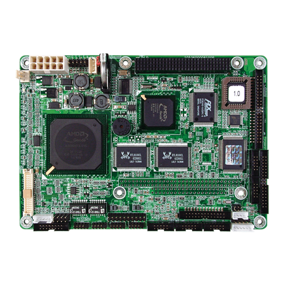
EmCORE-a5360
CPU
AMD Geode LX800
500MHz
LAN
1 x Realtek 8100CL
10/100 Base-T Ethernet
EPIC Compact Board
Quick Installation Guide
- 1 -
Version 1.2
Chipset
AMD Geode LX800 +
CS5536
Audio
Realtek ALC203 AC97
Audio CODEC, Line-in/
Line-out/ Mic-in
4041536000120P
Advertisement
Table of Contents

Related Manuals for Arbor Technology EmCORE-a5360


Summary of Contents for Arbor Technology EmCORE-a5360
- Page 1 EmCORE-a5360 EPIC Compact Board Quick Installation Guide Version 1.2 Form Factor Chipset EPIC compact board AMD Geode LX800 AMD Geode LX800 + 500MHz CS5536 Video Audio 18/24-bit TTL, Analog 1 x Realtek 8100CL Realtek ALC203 AC97 10/100 Base-T Ethernet Audio CODEC, Line-in/...
-
Page 2: Packing List
1 x Driver CD 1 x Quick Installation Guide 1 x ATX Power cable ATX main power connector (2x10-pin) to EmCORE-a5360 power connector (2x5-pin) If any of the above items is damaged or missing, contact your vendor immediately. Ordering Information... -
Page 3: Specifications
Specifications Form Factor EPIC Compact board Processor AMD Geode™ LX800 processor Chipset AMD LX800 + CS5536 System Memory 1 x 200-pin DDR SO-DIMM up to 1GB SDRAM AMD Geode LX series CPU integrated VGA VGA/ LCD Controller controller with 2D Engine (Shared memory Max. 64MB) Ethernet 2 x Realtek 8100CL 10/100 base-T Ethernet... -
Page 4: Board Dimensions
Board Dimensions 165.00 5.08 65.94 73.66 15.24 Unit:mm 80.01 102.56 102.77 107.85 Unit:mm PC 104 plus DIMM CF socket - 4 -... - Page 5 165.00 Unit:mm - 5 -...
- Page 6 Jumpers/ Connectors Quick Reference Jumpers Label Function JBAT1 Clear CMOS Setting JRS1 COM2 RS-232/422/485 Selection LLED1 LAN LED indicators Connectors Label Function SYSF1 Fan Power Connector ATX1 Power Supply Connector JFRT1 Switches and Indicators SMBUS1 External SMBUS Connector PC/104+ PCI Interface IDE1 IDE Connector FDD1...
-
Page 7: Jumpers & Connectors Location
Jumpers & Connectors Location JFRT1 ATX1 PC/104+ LPT1 INV1 LLED1 DIO1 LAN1 LAN2 AUDIO1 COM1 COM2 VGA1 USB1 USB2 JRS1 CON1 KBM1 - 7 -... - Page 8 Jumpers ATX1: Power Supply Connector (2) Connector type: 10-pin ATX Power Connector. JBAT1: Clear CMOS Setting (5) Connector type: Onboard 3-pin header. Desc. Desc. Mode PS-ON 1 2 3 4 Keep CMOS (Default) +12V +3.3V +5VSB Clear CMOS JRS1: COM2 RS-232/422/485 Selection -12V (16) JFRT1: Switches and Indicators (3)
- Page 9 PC/104+: PCI Interface (6) PME# B1 AD0 D1 VI/O AD2 B2 +5V D2 GND B3 AD3 D3 C/BE0# AD7 B4 AD6 D4 AD9 B5 GND D5 AD11 VI/O B6 AD10 M66EN D6 AD14 AD13 B7 AD12 D7 C/BE1# B8 +3.3V D8 +3.3V AD15 SERR#...
- Page 10 IDE1: IDE Connector (7) Description Description Connector type: Onboard 2.0mm pitch 2x22-pin box Drive density Select 0 headers. N/C (Key) Description Description Drive Density Select 1 IDE RESET Write Data# Index# DATA7 DATA8 Write Gate# Motor Enable A# DATA6 DATA9 Track 0# Driver Select B# DATA5...
- Page 11 IR1: Infrared Connector (14) DIO1: Digital I/O Connector (20) Connector type: Onboard 2.54mm pitch 5-pin Connector type: Onboard 2.54mm pitch 2x10-pin header. header. Voltage Description Description DIO1 DIO2 DIO3 DIO4 IRRX DIO5 DIO6 DIO7 DIO8 IRTX DIO9 DIO10 CON1: RS-422/ 485 Output Connector (15) DIO11 DIO12...
- Page 12 INV1: LCD Inverter Connector (25) LPT1: Parallel Port Connector (27) Connector type: Onboard 2.0mm pitch 5-pin Wafer. Connector type: Onboard 2.0mm pitch 2x13-pin box-header. Desc. Desc. STROBE Desc. Desc. PTD0 ERROR +12V PTD1 INIT Backlight on/off Brightness control PTD2 SLIN PTD3 PTD4 LCD1: TTL LCD Connector (26)
Need help?
Do you have a question about the EmCORE-a5360 and is the answer not in the manual?
Questions and answers