Table of Contents
Advertisement
Quick Links
Advertisement
Table of Contents

Related Manuals for Arbor Technology Em104-i230F


Summary of Contents for Arbor Technology Em104-i230F
- Page 1 Em104-i230F PC/104 CPU Module User’s Manual Version 1.0 2016.02...
- Page 2 This page is intentionally left blank. - 2 -...
- Page 3 Revision History Version Release Time Description February, 2016 Initial release - i -...
-
Page 4: Table Of Contents
Contents Table of Contents Revision History .................i Table of Contents ................ii Preface....................v Copyright Notice ..................v Declaration of Conformity ............... v CE ....................v FCC Class A ................... vi RoHS ....................vi SVHC / REACH ................vi Replacing Lithium Battery ..............vii Technical Support ..................vii Warranty....................viii Chapter 1 - Introduction ..............1... - Page 5 Contents Appendices ..................43 Appendix A. I/O Port Address Map ............44 Appendix B. Memory Address Map ............46 Appendix C. Interrupt Request Lines (IRQ) .......... 48 Appendix D: Watchdog Timer (WDT) Setting........49 - iii -...
- Page 6 This page is intentionally left blank. - iv -...
-
Page 7: Preface
Preface Preface Copyright Notice All Rights Reserved. The information in this document is subject to change without prior notice in order to improve the reliability, design and function. It does not represent a commitment on the part of the manufacturer. Under no circumstances will the manufacturer be liable for any direct, indirect, special, incidental, or consequential damages arising from the use or inability to use the product or documentation, even if advised of the possibility of such... -
Page 8: Fcc Class A
(PBDE) in electrical and electronic products. Member states of the EU are to enforce by 7/1/2006. ARBOR Technology Corp. hereby states that the listed products do not contain unintentional additions of lead, mercury, hex chrome, PBB or PBDB that exceed a maximum concentration value of 0.1% by weight or for cadmium exceed... -
Page 9: Replacing Lithium Battery
Preface (Substances of Very High Concern) in (EC) 1907/2006 (REACH --Registration, Evaluation, Authorization, and Restriction of Chemicals) regulated by the European Union. All substances listed in SVHC < 0.1 % by weight (1000 ppm) Warning Single Board Computers and their components contain very delicate Integrated Circuits (IC). -
Page 10: Warranty
Preface Warranty This product is warranted to be in good working order for a period of two years from the date of purchase. Should this product fail to be in good working order at any time during this period, we will, at our option, replace or repair it at no additional charge except as set forth in the following terms. -
Page 11: Chapter 1 Introduction
Chapter 1 Introduction Chapter 1 - Introduction - 1 -... -
Page 12: The Product
Introduction 1.1. The Product • Fanless Design • Support Intel Atom™ E3800 Family ® • Dual Gigabit Ethernet ports • LVDS, Analog RGB Port • Support Dual Independent Displays • Wide-Range Operating Temp.: -40 ~ 85°C 1.2. About this Manual This manual is intended for experienced users and integrators with hardware knowledge of computers. -
Page 13: Specifications
Introduction 1.3. Specifications System Soldered onboard Intel Atom™ processor ® E3825 dual-core 1.33GHz / E3845 quad-core 1.91GHz 1 x DDR3L SO-DIMM socket, supporting up to Memory 8GB 1333 MT/s SDRAM BIOS Insyde BIOS Watchdog Timer 1 ~ 255 levels reset I/O Chipset Fintek F81866 2 x RS-232... -
Page 14: Inside The Package
Introduction 1.4. Inside the Package Before starting to install the single board, make sure the following items are shipped: 1 x Em104-i230F 1 x Heat Sink 1 x Driver CD 1 x Quick Installation Guide If any of the above items is damaged or missing, contact your vendor immediately. -
Page 15: Chapter 2 Getting Started
Chapter 2 Getting Started Chapter 2 - Getting Started - 5 -... -
Page 16: Board Dimensions
Getting Started 2.1. Board Dimensions 90.17 85.09 82.55 8.89 5.08 Unit:mm - 6 -... -
Page 17: Block Diagram
Getting Started 2.2. Block Diagram PWR1 +5 DC-in DDR3L-1333MHz (up to 8GB) 1 x DDR3L USB3 1 x USB 2.0/3.0 port SO-DIMM socket Type A conn. Analog RGB VGA1 USB1 2 x USB 2.0 ports 1x13-pin headers 2x5-pin 2.00mm pitch latching box header 1 x eDP port Dual Channels 24-bit LVDS... -
Page 18: Jumpers And Connectors
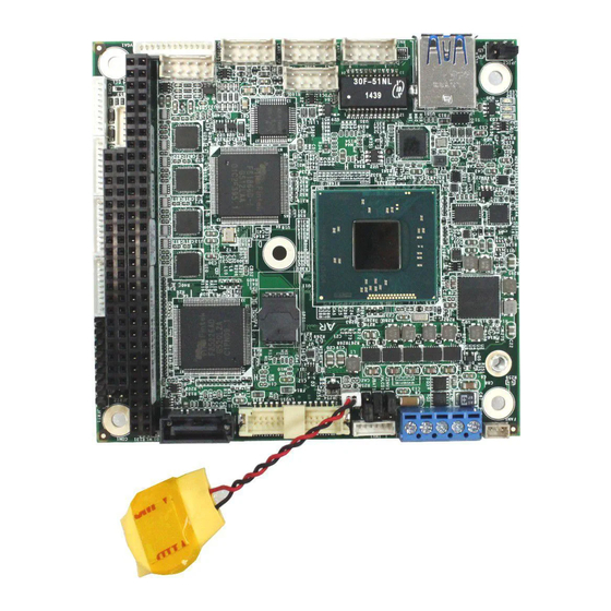
Getting Started 2.3. Jumpers and Connectors The board comes with some connectors to join some devices and also some jumpers to alter the hardware configuration. The following in this chapter will explicate each of these components one-by-one. 2.3.1. Layout This section will provide an overview of this board, both the top and bottom sides. Jumpers Location ❶... - Page 19 Getting Started Connectors Location PWR1 INV1 LVDS1 SATA1 FAN1 ⑱ ⑯ ⑲ ⑰ ⑮ C19 D19 ⑭ JFRT1 1 3 5 ⑬ COM4 ⑫ COM3 ⑨ CON1 ⑪ COM2 USB1 ① USB2 DIO1 ④ ⑩ COM1 ⑦ ② ③ ⑤ ⑥...
-
Page 20: Jumpers
Getting Started 2.3.2. Jumpers ❶ JINV1 Function: Sets LCD inverter voltage. (This jumper sets the voltage of LCD connector INV1, which means this jumper decides the pin 1 of the LCD connector INV1.) Jumper Type: 2.00mm pitch, 1x3-pin header Setting: Description +12V +5V (default) - Page 21 Getting Started ❷ JLVCD1 Function: Sets LCD panel voltage Jumper Type: 2.00mm pitch, 1x3-pin header Setting: Description +3.3V (default) Board Top ❶ ❸ JINV1 JBAT1 C19 D19 ❷ JLVCD1 1 3 5 ❹ JPIC1 - 11 -...
- Page 22 Getting Started ❸ JBAT1 Function: The voltage selection of LCD panel Jumper Type: 2.00mm pitch, 1x3-pin header Setting: Description Keeps CMOS (default) Clears CMOS Board Top ❶ ❸ JINV1 JBAT1 C19 D19 ❷ JLVCD1 1 3 5 ❹ JPIC1 ❹ JPIC1 Function: This jumper is for internal testing only.
-
Page 23: Connectors
Getting Started 2.3.3. Connectors USB1 Description: USB 3.0/2.0 Connector Connector Type: Type A connector Setting: The pin assignments conform to the industry standard. 1 2 3 4 Board Top C19 D19 1 3 5 USB1 ① - 13 -... - Page 24 Getting Started LAN1~2 Description: Ethernet Connectors Connector Type: 2.00mm pitch 2x5-pin wafer connector Setting: Description Description TX_MDI0- TX_MDI0+ MDI2+ RX_MDI1+ RX_MDI1- MDI2- MDI3- MDI3+ Board Top C19 D19 1 3 5 ② ③ LAN2 LAN1 - 14 -...
- Page 25 Getting Started USB2 Description: USB 2.0 Connector Connector Type: 2.00mm pitch 2x5-pin headers Setting: Pin Description Pin Description +5V- USBP1- USBP0- USBP1+ USBP0+ Board Top C19 D19 1 3 5 USB2 ④ - 15 -...
- Page 26 Getting Started AUDIO1 Description: AUDIO connector Connector Type: 2.00mm pitch 2x5-pin wafer connector Setting: Pin Description Pin Description LINE-R Line_L GND3 GND1 MIC1 GND4 GND2 LOUT_R LOUT_L Board Top C19 D19 1 3 5 ⑤ AUDIO1 - 16 -...
- Page 27 Getting Started VGA1 Description: Analog RGB Display Connector Connector Type: 1x13-pin ACES 1.25mm 86801-13 4-wall connector Setting: Description VGA_VSYNC VGA_HSYNC BLUE GREEN Board Top C19 D19 1 3 5 ⑥ VGA1 - 17 -...
- Page 28 Getting Started DIO1 Description: DIO Connector Connector Type: 2.00mm pitch 2x5-pin wafer connector Setting: Description Pin Description DIO1 DIO0 DIO3 DIO2 DIO5 DIO4 DIO7 DIO6 Board Top C19 D19 1 3 5 DIO1 ⑦ - 18 -...
- Page 29 Getting Started KBMS1 Description: Connector for keyboard and mouse. Connector Type: 1x6-pin CVILUX 1.25mm CI4406P1V00- LF 4-wall connector Setting: Description KB_DATA KB_CLK PS2_VCC MS_DATA MS_CLK Board Top C19 D19 1 3 5 ⑧ KBMS1 - 19 -...
- Page 30 Getting Started CON1 Description: PC/104 interface Connector Type: The pin assignments conform to the industry standard. Board Top C19 D19 1 3 5 ⑨ CON1 - 20 -...
- Page 31 Getting Started COM1~2 Description: RS-232/422/485 Serial Ports Connector Type: 1x9-pin ACES 1.25mm 86801-09 4-wall connector Setting: RS-232 RS-422 RS-485 Desc. Desc. Desc. DCD# DSR# RTS# CTS# DTR# Board Top C19 D19 1 3 5 ⑪ COM2 ⑩ COM1 - 21 -...
- Page 32 Getting Started COM3~4 Description: RS232-interfaced serial port Connector Type: 2.00mm pitch 2x5-pin header Setting: RS-232 Desc. DCD# DSR# RTS# CTS# DTR# Board Top C19 D19 1 3 5 ⑬ COM4 ⑫ COM3 - 22 -...
- Page 33 Getting Started JFRT1 Description: Connector for reset, power LED, HDD LED and speaker Connector Type: 2.54mm pitch 1x8-pin header Setting: Description RESET PWR LED+ HDD LED+ HDD LED- SPKOUT+ SPKOUT- Board Top C19 D19 ⑭ JFRT1 1 3 5 - 23 -...
- Page 34 Getting Started SATA1 Description: Serial ATA connector Connector Type: High speed transfer rates (300MB/s). Setting: Description Board Top SATA1 ⑮ C19 D19 1 3 5 - 24 -...
- Page 35 Getting Started LVDS1 Description: Connector for LCD panel. Connector Type: DF-13-30DP-1.25V connector Setting: Pin Description Description TX2CLK+ TX1CLK+ TX2CLK- TX1CLK- 10 TX2_D0+ TX1_D0+ 12 TX2_D0- TX1D0- 14 GND 16 TX2_D1+ TX1D1+ 18 TX2_D1- TX1D1- 20 GND 22 TX2D2+ TX1D2+ 24 TX2D2- TX1D2- 26 GND 28 TX2D3+...
- Page 36 Getting Started INV1 Description: LCD Inverter Connector Connector Type: 1x6-pin CVILUX 1.25mm CI4406P1V00- LF 4-wall connector Setting: Description INV_VCC INV_VCC BKLT_EN BKLT_CTRL Board Top INV1 ⑰ C19 D19 1 3 5 - 26 -...
- Page 37 Getting Started PWR1 Description: 12V/5V power input Connector Type: 1x5-pin terminal Setting: Description VCC 12V VCC 5V VCC 5V Board Top PWR1 ⑱ C19 D19 1 3 5 - 27 -...
- Page 38 Getting Started FAN1 Description: FAN Connector Connector Type: 1.25mm pitch 1x3-pin wafer connector Setting: Description Board Top FAN1 ⑲ C19 D19 1 3 5 - 28 -...
- Page 39 Getting Started CON3 Description: mSATA Full-Size Socket Connector Type: 52-pin mSATA Full-Size Socket Setting: The pin assignments conform to the industry standard. (Socket shared and BIOS selectable with Mini-card) As for configuration, please refer to Mini PCI Express Support in 3.2.2.
-
Page 40: Driver Installation Notes
Getting Started 2.4. Driver Installation Notes The CPU board supports Windows 7 and Windows 8.1. Find the necessary drivers on the CD that comes with your purchase. For different OS, the driver/ utility installation may vary slightly, but generally they are similar. Windows 7 Device Driver Path... -
Page 41: Chapter 3 - Bios
Chapter 3 BIOS Chapter 3 - BIOS - 31 -... - Page 42 BIOS The BIOS Setup utility is to configure the system settings stored in the system’s BIOS ROM. BIOS is activated once the computer powers on. After entering the utility, use the left/right arrow keys to navigate between the top menus and use the down arrow key to access one. Menu Description Main...
-
Page 43: Main
BIOS 3.1. Main The Main menu displays some BIOS info and features the settings of System Date and System Time. The BIOS info displayed is: Info Item Description BIOS Version Delivers the computer’s BIOS version. Project name Delivers the name of the project Delivers the date and time when the BIOS Setup utility was created/ Build Date and Time updated. -
Page 44: Advanced
BIOS 3.2. Advanced The Advanced menu controls the system’s CPU, IDE, Super IO, AHCI and USB. It also helps users monitor hardware health. The featured submenus are: Submenu Description Boot Configuration 3.2.1. Boot Configuration on page 35. On Board Device Support 3.2.2. -
Page 45: Boot Configuration
BIOS 3.2.1. Boot Configuration Setting Description Numlock Select Power-on state for Num lock 3.2.2. On Board Device Support Configures On-board devices by the following settings: Setting Description RTL8111E Gigabit Enables/Disables On Board LAN Configuration Ethernet Controller 1/2 Mini PCI Express Support Options are: Enabled, Disabled, mSATA Enabled is the default. -
Page 46: Video Configuration
BIOS 3.2.3. Video Configuration Configure video settings The featured setting is: 3.2.3.1 Video Configuration Setting Description Set Logo & SCU Resolution. Logo & SCU Resolution Options are Auto/640 x480/800 x 600/1024 x 768 3.2.3.2 VBT Hook Configuration Setting Description Set the option of CRT. Configure CRT as Options are CRT / No Device CRT EDID Support... -
Page 47: Sata Configuration
BIOS 3.2.4. SATA Configuration Select this submenu to configure the SATA controller and HD. Setting Description Enables/disables the present SATA controller. SATA Controller Enabled is the default. Configures how to sun the SATA drives. Configures SATA Mode Options available are AHCI (default) and IDE. SATA Port 0 Hot Plug Enables/disables hot-pluggable feature for the SATA Capability... -
Page 48: Sio Fintek81866D
BIOS 3.2.5. SIO FINTEK81866D Configures SIO by the following settings: Setting Description Voltage Display the voltage info Display thermal info Thermal CPU Temperature SYSTEM Temperature Set the state of Power Loss mode Power Loss mode Options are Always On(default)/Always Off Serial Port A/B Enables/disables the Serial port. -
Page 49: Security
BIOS 3.3. Security The Security menu sets up the password for the system’s administrator account. Once the administrator password is set up, this BIOS Setup utility is limited to access and will ask for the password each time any access is attempted. The featured setting is: Setting Description... -
Page 50: Boot
BIOS 3.4. Boot The Boot menu configures how to boot up the system such as the configuration of boot device priority. The featured settings are: Setting Description Set the boot type. Boot Type Options are Legacy Boot Type , UEFI Type. Allow InsydeH20 to Skip certain tests while booting . - Page 51 BIOS Boot Device Priority Normal Boot Menu Select Normal boot option priority or Advance boot option Priority. Legacy Boot type order Change boot type order Hard Disk Drive Change CD/DVD-ROM Drive Boot order - 41 -...
-
Page 52: Exit
BIOS 3.5. Exit The Save & Exit menu features a handful of commands to launch actions from the BIOS Setup utility regarding saving changes, quitting the utility and recovering defaults. The features settings are: Setting Description Exit Saving Changes Saves the changes and quits the BIOS Setup utility. Save Changes Without Exit Save Changes but does not quit the BIOS. -
Page 53: Appendices
Appendices Appendices - 43 -... -
Page 54: Appendix A. I/O Port Address Map
Appendices Appendix A. I/O Port Address Map Each peripheral device in the system is assigned a set of I/O port addresses which also becomes the identity of the device. The following table lists the I/O port addresses used. Address Device Description 0x000003F8-0x000003FF Communications Port (COM1) 0x000002F8-0x000002FF... - Page 55 Appendices Address Device Description 0x00000080-0x0000008F Motherboard resources 0x00000092-0x00000092 Motherboard resources 0x000000B2-0x000000B3 Motherboard resources 0x00000680-0x0000069F Motherboard resources 0x00000000-0x0000006F PCI bus 0x00000078-0x00000CF7 PCI bus 0x00000D00-0x0000FFFF PCI bus 0x00000020-0x00000021 Programmable interrupt controller 0x00000024-0x00000025 Programmable interrupt controller 0x00000028-0x00000029 Programmable interrupt controller 0x0000002C-0x0000002D Programmable interrupt controller 0x00000030-0x00000031 Programmable interrupt controller 0x00000034-0x00000035...
-
Page 56: Appendix B. Memory Address Map
Appendices Appendix B. Memory Address Map Address Device Description 0x90810000-0x90813FFF High Definition Audio Controller 0xFED00000-0xFED003FF High precision event timer 0xFF000000-0xFFFFFFFF Intel(R) 82802 Firmware Hub Device 0xA0000-0xBFFFF Intel(R) Atom(TM) Processor E3800 Series/Intel(R) Celeron(R) Processor N2920/J1900 0x80000000-0x908FFFFE Intel(R) Atom(TM) Processor E3800 Series/Intel(R) Celeron(R) Processor N2920/J1900 0x90000000-0x903FFFFF Intel(R) Atom(TM) Processor E3800 Series/Intel(R) Celeron(R) - Page 57 Appendices Address Device Description 0x80000000-0x908FFFFE PCI Bus 0x90504000-0x90504FFF Realtek PCIe GBE Family Controller 0x90500000-0x90503FFF Realtek PCIe GBE Family Controller 0x90404000-0x90404FFF Realtek PCIe GBE Family Controller #2 0x90400000-0x90403FFF Realtek PCIe GBE Family Controller #2 0x90817000-0x90817FFF SDA Standard Compliant SD Host Controller 0x90816000-0x90816FFF SDA Standard Compliant SD Host Controller - 47 -...
-
Page 58: Appendix C. Interrupt Request Lines (Irq)
Appendices Appendix C. Interrupt Request Lines (IRQ) Peripheral devices use interrupt request lines to notify CPU for the service required. The following table shows the IRQ used by the devices on board. Level Function IRQ0 System timer IRQ1 Standard PS/2 Keyboard IRQ3 Communications Port (COM2) IRQ4... -
Page 59: Appendix D: Watchdog Timer (Wdt) Setting
Appendices Appendix D: Watchdog Timer (WDT) Setting WDT is widely used for industrial application to monitor CPU activities. The application software depends on its requirement to trigger WDT with adequate timer setting. Before WDT timeout, the functional normal system will reload the WDT.
Need help?
Do you have a question about the Em104-i230F and is the answer not in the manual?
Questions and answers