
Related Manuals for Arbor Technology EmETXe-i89U0


Summary of Contents for Arbor Technology EmETXe-i89U0
- Page 1 EmETXe-i89U0 COM Express Compact ® Type 6 CPU Module User’s Manual Version 1.1 2017.03...
- Page 2 Revision History Version Date Description August, 2016 Initial release March,2017 Modify Memory...
-
Page 3: Table Of Contents
Contents Preface Copyright Notice ..............iii Declaration of Conformity ..........iii CE ..................iii FCC Class B .................iii RoHS ..................iv SVHC / REACH ..............iv Warning ................v Replacing the Lithium Battery ...........v Technical Support ..............v Warranty ................vi Chapter 1 - Introduction 1.1 The Product ..............2 1.2 About This Manual............2 1.3 Specifications ..............3 1.4 Inside the Package ............4... - Page 4 Content Chapter 4 - BIOS 4.1 Main ................20 4.2 Advanced..............22 4.2.1 CPU Configuration ...........23 4.2.2 PCI Subsystem Settings ..........25 4.2.3 Trusted Computing ...........26 4.2.4 ACPI Settings ............27 4.2.5 USB Configuration ...........28 4.2.6 AMT Configuration ...........30 4.2.7 SATA Configuration ..........31 4.2.8 Hardware Monitor .............32 4.2.9 Super IO Configuration ..........33 4.2.10 S5 RTC Wake Settings ...........35 4.2.11 CSM Configuration ..........36...
-
Page 5: Preface
Preface Copyright Notice All Rights Reserved. The information in this document is subject to change without prior notice in order to improve the reliability, design and function. It does not represent a commitment on the part of the manufacturer. Under no circumstances will the manufacturer be liable for any direct, indirect, special, incidental, or consequential damages arising from the use or inability to use the product or documentation, even if advised of the possibility of such damages. -
Page 6: Rohs
RoHS ARBOR Technology Corp. certifies that all components in its products are in compliance and conform to the European Union’s Restriction of Use of Haz- ardous Substances in Electrical and Electronic Equipment (RoHS) Directive 2002/95/EC. -
Page 7: Warning
Preface Warning Single Board Computers and their components contain very delicate Integrated Circuits (IC). To protect the Single Board Computer and its components against damage from static electricity, you should always follow the following precautions when handling it : 1. Disconnect your Single Board Computer from the power source when you want to work on the inside. -
Page 8: Warranty
Preface Warranty This product is warranted to be in good working order for a period of two years from the date of purchase. Should this product fail to be in good working order at any time during this period, we will, at our option, replace or repair it at no additional charge except as set forth in the following terms. -
Page 9: Chapter 1 Introduction
Introduction Chapter 1 Introduction - 1 -... -
Page 10: The Product
Introduction 1.1 The Product The EmETXe-i89U0 is a space-conscious CPU board of 95 mm x 95 mm to take up only small footprint in your system. By the architecture of Type 6, the board has two high-performance connectors to promise stable data passing rate. -
Page 11: Specifications
Introduction 1.3 Specifications Specifications System ® Soldered onboard 6th Generation Intel Core™ i7-6600U 2.6GHz (Base)/ 3.4GHz (Turbo), i5-6300U 2.3GHz (Base)/ 2.8GHz (Turbo), i3-6100U 2.3GHz (Base), ® Celeron 3955U 2.3GHz (Base) Memory 2 x DDR4 SO-DIMM sockets BIOS AMI UEFI BIOS Watchdog Timer 1~255 levels reset USB 2.0... -
Page 12: Inside The Package
1.4 Inside the Package Before you begin installing your single board, please make sure that the following materials have been shipped: 1 x EmETXe-i89U0 COM Express CPU Module 1 x Driver CD 1 x Quick Installation Guide If any of the above items is damaged or missing, contact your vendor immediately. -
Page 13: Optional Accessories
Introduction 1.5.1 Optional Accessories Heat spreader with threaded standoffs (bore hole) HS-89U0-F2-T (95x95x11mm) Heat spreader non-threaded standoffs (bore hole) HS-89U0-F2-NT (95x95x11mm) HS-89U0-C1 Heat sink with FAN 95x95x29mm Universal evaluation heatsink kit w/ thermal pad HS-0000-W4 (dimensions: 125x95x22mm, only used on a flat type heat spreader) COM Express Type 6 evaluation carrier board with... - Page 14 This page is intentionally left blank. - 6 -...
-
Page 15: Chapter 2 - Board Overview
Board Overview Chapter 2 Board Overview - 7 -... -
Page 16: What Is "Com Express
Module Type 1 and 10 support single connector with two rows (220 pins). Module Type 2, 3, 4, 5 and 6 support two connectors with four rows (440 pins). EmETXe-i89U0 is a Type-6 module. Difference between Standard Type 6 and EmETXe-i89U0 is listed as below: Module Type Standard Type 6... -
Page 17: Board Dimensions
Board Overview 2.2 Board Dimensions The following illustration shows the dimension of EmETXe-i89U0, with the mea- surements in width, depth, and height called out. DIMM1 DIMM2 Unit:mm - 9 -... -
Page 18: Block Diagram
Board Overview 2.3 Block Diagram 2 x SO-DIMM DDR4 DDR4 1866/2133MT/s sockets DDI Port B DDI Port C 4 x USB SS ports 2 x PCIex1 Dual Chnnels 24-bit LVDS PTN3460 HD Audio Link SATA0, 1 6th Generation 8 x USB 2.0 Ports Intel Core i7/ i5/ i3/ ®... -
Page 19: Connector Pin Definition
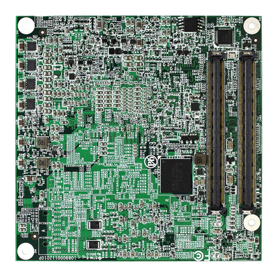
Board Overview 2.4 Connector Pin Definition Being a most commonly-used Type 6, the EmETXe-i89U0 features two board- to-board connectors on bottom side. Top Side Bottom Side COM Express AB Connector COM Express AB Connector COM Express CD Connector COM Express CD Connector... - Page 20 Board Overview COM Express AB Connector (bottom side) GND (FIXED) GND (FIXED) PCIE_RX4- PCIE_TX4- GBE0_ACT# GBE0_MDI3- GPO2 LPC_FRAME# GBE0_MDI3+ PCIE_RX3+ PCIE_TX3+ LPC_AD0 GBE0_LINK100# PCIE_TX3- PCIE_RX3- LPC_AD1 GBE0_LINK1000# LPC_AD2 GBE0_MDI2- PCIE_RX2+ PCIE_TX2+ LPC_AD3 GBE0_MDI2+ PCIE_TX2- PCIE_RX2- LPC_DRQ0# GPO3 GPI1 LPC_DRQ1# GBE0_MDI1- PCIE_RX1+ PCIE_TX1+ LPC_CLK...
- Page 21 Board Overview COM Express CD Connector (bottom side) GND(FIXED) GND (FIXED) TYPE2# USB_SSTX0- USB_SSRX0- USB_SSTX0+ USB_SSRX0+ GND (FIXED) GND (FIXED) USB_SSTX1- USB_SSRX1- USB_SSTX1+ USB_SSRX1+ USB_SSTX2- USB_SSRX2- USB_SSTX2+ USB_SSRX2+ GND (FIXED) GND (FIXED) USB_SSTX3- USB_SSRX3- USB_SSRX3+ USB_SSTX3+ DDI1_CTRLCLK_AUX+ GND (FIXED) GND (FIXED) DDI1_CTRLCLK_AUX- RSVD RSVD...
- Page 22 This page is intentionally left blank. - 14 -...
-
Page 23: Chapter 3 - Installation & Maintenance
Installation & Maintenance Chapter 3 Installation & Maintenance - 15 -... -
Page 24: Installing The Cpu Module On Carrier Board
1. Find the COM Express connectors on carrier board PBE-1705, which is available in Section 1.5.1 Optional Accessories on page 2. Embed EmETXe-i89U0 into PBE-1705 via COM Express connectors as below; that is, COM Express AB to AB and CD to CD. - 16 -... -
Page 25: Installing The Heatsink
Installation & Maintenance 3.2 Installing the Heatsink 1. Locate EmETXe-i89U0 mounted on PBE-1705. 2. Prepare the heatspred included in optional accessories. (See section 1.5.1 Optional Accessories on page 5) Put heatspred on the CPU module and lock it. Make sure thermal grease in contact with CPU and chipset on CPU module. - Page 26 This page is intentionally left blank. - 18 -...
-
Page 27: Chapter 4 - Bios
BIOS Chapter 4 BIOS - 19 -... -
Page 28: Main
Aptio Setup Utility - Copyright (C) 2016 American Megatrends, Inc. Advanced Chipset Security Boot Save & Exit Main Set the Date. Use Tab BIOS Information to Switch between Date Project Name EmETXe-i89U0 elements. BIOS Version 1.00 Build Date and Time 04/10/2016 14:35:49 Access Level Administrator EC Version 1.00... - Page 29 BIOS Set the system time. Use Tab to switch between Time elements. System Time The time format is: Hour: 00 to 23 ► Minute: 00 to 59 Second: 00 to 59 Key Commands BIOS Setup Utility is mainly a key-based navigation interface. Please refer to the following key command instructions for navigation process.
-
Page 30: Advanced
BIOS 4.2 Advanced Aptio Setup Utility - Copyright (C) 2016 American Megatrends, Inc. Main Chipset Security Save & Exit Boot Advanced CPU Configuration ► CPU Configuration Parameters ► PCI Subsystem Settings ► Trusted Computing ► ACPI Settings ► USB Configuration ►... -
Page 31: Cpu Configuration
BIOS 4.2.1 CPU Configuration Aptio Setup Utility - Copyright (C) 2016 American Megatrends, Inc. Advanced CPU Configuration Enabled for Windows XP Intel(R) Core(TM) i7-6600U CPU @ 2.60GHz and Linux (OS CPU Signature optimized for Hyper- 406E3 Microcode Patch Threading Technology) Max CPU Speed and Disabled for other 2600 MHz... - Page 32 BIOS Set the performance state that the BIOS will set before Boot performance the OS handoff. Mode Options: Max Battery, Max Non-Turbo Perfor- ► mance and Turbo Performance (default). Intel (R) Speed Step Enable (default)/Disable Intel SpeedStep (tm) Only available when Intel Speed Step is Enabled. Turbo Mode Enable (default)/Disable Turbo Mode CPU C States...
-
Page 33: Pci Subsystem Settings
BIOS 4.2.2 PCI Subsystem Settings Aptio Setup Utility - Copyright (C) 2016 American Megatrends, Inc. Advanced PCI Bus Driver Version A5.01.08 Enables or Disables 64bit capable Devices to be Decoded in Above PCI Device Common Setttings: [Disabled] 4G Address Space (Only Above 4G Decoding if System Supports 64 bit PCI Decoding). -
Page 34: Trusted Computing
BIOS 4.2.3 Trusted Computing Aptio Setup Utility - Copyright (C) 2016 American Megatrends, Inc. Advanced Configuration Enables or disables Security Device Support [Enable] BIOS support for [Enabled] TPM State security device. Pending Operation [None] O.S. will not show [Auto] Device Select Security Device. -
Page 35: Acpi Settings
BIOS 4.2.4 ACPI Settings Aptio Setup Utility - Copyright (C) 2016 American Megatrends, Inc. Advanced ACPI Settings Enables or Disables System ability to Enable Hibernation Hibernate (OS/S4 Sleep [Enabled] ACPI Sleep State State). This option [S3 (Suspend to RAM)] may be not effective with some OS. -
Page 36: Usb Configuration
BIOS 4.2.5 USB Configuration Aptio Setup Utility - Copyright (C) 2012 American Megatrends, Inc. Aptio Setup Utility - Copyright (C) 2016 American Megatrends, Inc. Advanced USB Configuration Enables Legacy USB support. AUTO option disables legacy USB Module Version support if no USB devices are connected. - Page 37 BIOS USB hardware delay and time-out Use this item to set the time-out value for control, bulk, and interrupt transfers. USB Transfer time-out Options available are: 1 sec, 5 sec, 10 sec, 20 sec (de- fault) Use this item to set USB mass storage device start unit com- mand time-out.
-
Page 38: Amt Configuration
BIOS 4.2.6 AMT Configuration Aptio Setup Utility - Copyright (C) 2012 American Megatrends, Inc. Aptio Setup Utility - Copyright (C) 2016 American Megatrends, Inc. Advanced Enable/Disable Intel Intel AMT [Enabled] (R) Active Management Technology BIOS Extension. Note : iAMT H/W is always enabled. -
Page 39: Sata Configuration
BIOS 4.2.7 SATA Configuration Aptio Setup Utility - Copyright (C) 2012 American Megatrends, Inc. Aptio Setup Utility - Copyright (C) 2016 American Megatrends, Inc. Advanced SATA Controller(s) [Enabled] Enable or disable SATA Device. SATA Mode Selection [AHCI] Serial ATA Port 1 Empty Port 1 [Enabled]... -
Page 40: Hardware Monitor
BIOS 4.2.8 Hardware Monitor Aptio Setup Utility - Copyright (C) 2012 American Megatrends, Inc. Aptio Setup Utility - Copyright (C) 2016 American Megatrends, Inc. Advanced Pc Health Status CPU Tempreture : +37 Fan1 Speed : 4607 RPM VCORE : +0.858 V VCCDU : +1.189 V : +11.942 V... -
Page 41: Super Io Configuration
BIOS 4.2.9 Super IO Configuration Aptio Setup Utility - Copyright (C) 2012 American Megatrends, Inc. Aptio Setup Utility - Copyright (C) 2016 American Megatrends, Inc. Advanced Super IO Configuration Set Parameters of Serial Port 1 (CON1) Super IO Chip IT8528 ►... - Page 42 BIOS Serial Port 1/2/3/4 Configuration Setting Description Serial Port Enable (default) or Disable Serial Port (COM). Select an optimal setting for Super IO device. Options for Serial Port 1: ► Auto; IO=3F8h; IRQ=4 (default) ; IO=3F8h; IRQ=3, 4, 7, 12; IO=2F8h;...
-
Page 43: S5 Rtc Wake Settings
BIOS Parallel Port Configuration Setting Description Parallel Port Enable (default) or Disable Parallel Port (LPT/LPTE). Select an optimal setting for Super IO device. Options: ► Auto IO=378h; IRQ=7 (default) Change Settings IO=378h; IRQ=7, 10, 11, 12 IO=278h; IRQ=7, 10, 11, 12 IO=3BCh;... -
Page 44: Csm Configuration
BIOS 4.2.11 CSM Configuration Aptio Setup Utility - Copyright (C) 2016 American Megatrends, Inc. Advanced Compatibility Support Module Configuration Enable/Disable CSM Support. CSM Support [Enabled] CSM16 Module Version 07.79 Boot option filter [UEFI and Legacy] Option ROM execution →←: Select Screen [Do not launch] Network ↓↑: Select Item... -
Page 45: Chipset
BIOS 4.3 Chipset Aptio Setup Utility - Copyright (C) 2016 American Megatrends, Inc. Main Advanced Boot Security Save & Exit Chipset VT-d capability VT-d [Enabled] Above 4GB MMIO BIOS assignment [Disabled] PCH-IO Configuration ► PCI Express Configuration ► HD Audio Configuration ►... - Page 46 BIOS Control Detection of the HD-Audio device. Options available are: ► Disabled: HDA will be unconditionally disabled HD Audio Configuration Enabled: HDA will be unconditionally Enabled Auto (default) = HDA will be enabled if present, disabled otherwise. Enables/Disables onboard NIC. Options: Enabled (default) and Disabled ►...
-
Page 47: Pci Express Configuration
BIOS 4.3.1 PCI Express Configuration Aptio Setup Utility - Copyright (C) 2016 American Megatrends, Inc. Chipset PCI Express Root Port 1 PCI Express Configuration Settings. ► PCIE1 ► PCIE2 ► PCIE3 ► MC1 ► MC2 →←: Select Screen ↓↑: Select Item Enter: Select +/-: Change Opt. -
Page 48: Graphics Configuration
BIOS 4.3.2 Graphics Configuration Setting Description Graphics Turbo Sets the graphics turbo IMON current values. IMON Current Options available are 14 to 31(default). ► Set the Primary PEG device. Primary PEG Options: Auto(default), PEG11, and PEG12. ► Keep IGD enabled based on the setup options. Internal Graphics Options: Auto(default), Disabled and Enabled. -
Page 49: Memory Configuration
BIOS 4.3.3 Memory Configuration Aptio Setup Utility - Copyright (C) 2016 American Megatrends, Inc. Chipset Memory Information Memory RC Version 1.9.0.0 Memory Frequency 2133 Mhz Total Memory 8192 MB 1200 DIMM#0 Not Present DIMM#1 8192 MB Memory Timings (tCL-tRCD-tRP-tRAS) 15-36 →←: Select Screen ↓↑: Select Item Enter: Select... -
Page 50: Lcd Control
BIOS 4.3.4 LCD Control Setting Description Select the Video Device which will be activated during POST. This has no effect if external graphics present. Sec- Primary IGFX ondary boot display selection will appear based on your Boot Display selection. VGA modes will be supported only on primary display. -
Page 51: Security
BIOS 4.4 Security The Security menu sets up the administrator password. Aptio Setup Utility - Copyright (C) 2016 American Megatrends, Inc. Boot Main Advanced Chipset Save & Exit Security Set Administrator Password Description Password Minimum length Maximum length Administrator Password →←: Select Screen ↓↑: Select Item Enter: Select... -
Page 52: Boot
BIOS 4.5 Boot Aptio Setup Utility - Copyright (C) 2016 American Megatrends, Inc. Boot Main Advanced Chipset Security Save & Exit Select the keyboard Boot Configuration NumLock state Bootup NumLock State [On] Quiet Boot [Disabled] Boot Option Priorities Driver Option Priorities →←: Select Screen ↓↑: Select Item Enter: Select... -
Page 53: Save & Exit
BIOS 4.6 Save & Exit Aptio Setup Utility - Copyright (C) 2016 American Megatrends, Inc. Main Advanced Chipset Security Boot Save & Exit Exit system setup Save Options after saving the Save Changes and Exit changes. Discard Changes and Exit Default Options Restore Defaults Lauch EFI Shell from filesystem device... -
Page 54: Appendix
Appendix Appendix - 46 -... -
Page 55: Appendix A: I/O Port Address Map
Appendix Appendix A: I/O Port Address Map Each peripheral device in the system is assigned a set of I/O port addresses which also becomes the identity of the device. The following table lists the I/O port addresses used. Address Device Description 03F8-03FF Communications Port (COM1) 02F8-02FF... -
Page 56: Appendix B: Bios Memory Mapping
Appendix Appendix B: Interrupt Request Lines (IRQ) Peripheral devices use interrupt request lines to notify CPU for the service required. The following table shows the IRQ used by the devices on board. Level Function IRQ0 System timer IRQ1 PS/2 Keyboard IRQ3 Communications Port (COM2) IRQ4... -
Page 57: Appendix D: Watchdog Timer (Wdt) Setting
Appendix Appendix D: Watchdog Timer (WDT) Setting WDT is widely used for industry application to monitor the activity of CPU. Ap- plication software depends on its requirement to trigger WDT with adequate timer setting. Before WDT time out, the functional normal system will reload the WDT. - Page 58 Appendix delay(DELAY_TIME); /* Watchdog Timer Control Register */ SMB_Byte_WRITE(SMB_PORT_AD,SMB_DEVICE_ADD,0x36,0x72); int WDT_Count(void) int iData; /* Watchdog Timer Range Register */ iData = SMB_Byte_READ(SMB_PORT_AD,SMB_DEVICE_ADD,0x37); return iData; void WDT_Clear(int iCount) /* Watchdog Timer Range Register */ SMB_Byte_WRITE(SMB_PORT_AD,SMB_DEVICE_ADD,0x37,iCount); void WDT_Stop(void) /* Watchdog Timer Control Register */ SMB_Byte_WRITE(SMB_PORT_AD,SMB_DEVICE_ADD,0x36,0x52); - 50 -...
Need help?
Do you have a question about the EmETXe-i89U0 and is the answer not in the manual?
Questions and answers