
Subscribe to Our Youtube Channel
Related Manuals for Arbor Technology EmETXe-a10M3


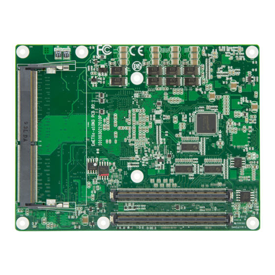
Summary of Contents for Arbor Technology EmETXe-a10M3
- Page 1 EmETXe-a10M3 COM Express Basic ® Type 6 CPU Module User’s Manual Version 1.1 2021.06...
- Page 2 Revision History Version Date Description 2020.04 Initial release 2021.06 Revise optional accessory items...
-
Page 3: Table Of Contents
Contents Preface Copyright Notice ..............iii Declaration of Conformity ..........iii CE ..................iii FCC Class B .................iii RoHS ..................iv SVHC / REACH ..............iv Warning ................v Replacing the Lithium Battery ...........v Technical Support ..............v Warranty ................vi Chapter 1 - Introduction 1.1 The Product ..............2 1.2 About This Manual............2 1.3 Specifications ..............3 1.4 Inside the Package ............4... - Page 4 Content Chapter 4 - BIOS 4.1 Main ................20 4.2 Advanced..............22 4.2.1 AMD CBS ..............23 4.2.2 CPU Configuration ...........24 4.2.3 AMD fTPM Configuration .........25 4.2.4 PCI Subsystem Settings ..........26 4.2.5 ACPI Settings ............27 4.2.6 Trusted Computing ...........28 4.2.7 NVMe Configuration ..........29 4.2.8 USB Configuration ...........30 4.2.9 Network Stack Configuration ........32 4.2.10 Super IO Configuration ..........33...
-
Page 5: Preface
Preface Copyright Notice All Rights Reserved. The information in this document is subject to change without prior notice in order to improve the reliability, design and function. It does not represent a commitment on the part of the manufacturer. Under no circumstances will the manufacturer be liable for any direct, indirect, special, incidental, or consequential damages arising from the use or inability to use the product or documentation, even if advised of the possibility of such damages. -
Page 6: Rohs
RoHS ARBOR Technology Corp. certifies that all components in its products are in compliance and conform to the European Union’s Restriction of Use of Haz- ardous Substances in Electrical and Electronic Equipment (RoHS) Directive 2002/95/EC. -
Page 7: Warning
Preface Warning Single Board Computers and their components contain very delicate Integrated Circuits (IC). To protect the Single Board Computer and its components against damage from static electricity, you should always follow the following precautions when handling it : 1. Disconnect your Single Board Computer from the power source when you want to work on the inside. -
Page 8: Warranty
Preface Warranty This product is warranted to be in good working order for a period of two years from the date of purchase. Should this product fail to be in good working order at any time during this period, we will, at our option, replace or repair it at no additional charge except as set forth in the following terms. -
Page 9: Chapter 1 Introduction
Introduction Chapter 1 Introduction - 1 -... -
Page 10: The Product
Introduction 1.1 The Product The EmETXe-a10M3 is a space-conscious CPU board of 125 mm x 95 mm to take up only small footprint in your system. By the architecture of Type 6, the board has two high-performance connectors to promise stable data passing rate. -
Page 11: Specifications
Introduction 1.3 Specifications System Soldered onboard AMD Ryzen V1000 V1605B 2.0GHz(Base)/ 3.6GHz (Turbo) or V1756B 3.25GHz(Base)/ 3.6GHz (Turbo) or V1807B 3.25GHz(Base)/ 3.8GHz (Turbo) processor 2 x DDR4 ECC SO-DIMM sockets, supporting up Memory to 32GB SDRAM BIOS AMI UEFI BIOS Watchdog Timer 1~255 levels reset USB Port... -
Page 12: Inside The Package
Before you begin installing your single board, please make sure that the following materials have been shipped: 1 x EmETXe-a10M3 COM Express CPU Module 1 x Quick Installation Guide If any of the above items is damaged or missing, contact your vendor immediately. -
Page 13: Optional Accessories
Introduction 1.5.1 Optional Accessories Heat sink with Fan, PAD (95x95x51mm) HS-10M3-C1 ® COM Express Type 6 evaluation carrier board with SIO PBE-1705-F1 F71869ED module in ATX form factor Cable kit CBK-03-1705-00 1 x SATA cable 2 x COM Flat cables 1.6 Driver(7.2A) Installation To install the drivers, please visit our website at www.arbor.technology. - Page 14 This page is intentionally left blank. - 6 -...
-
Page 15: Chapter 2 - Board Overview
Board Overview Chapter 2 Board Overview - 7 -... -
Page 16: What Is "Com Express
Module Type 1 and 10 support single connector with two rows (220 pins). Module Type 2, 3, 4, 5 and 6 support two connectors with four rows (440 pins). EmETXe-a10M3 is a Type-6 module. Difference between Standard Type 6 and EmETXe-a10M3 is listed as below: Module Type... -
Page 17: Board Dimensions
Board Overview 2.2 Board Dimensions 2,7 * 6.0 (5,2) 62,87 (3,9) Unit: mm - 9 -... -
Page 18: Block Diagram
Board Overview 2.3 Block Diagram SODIMM1, 2 DDR4-2400MT/s DDI0 (DP, BOM optional, w/o LVDS) DDR4 SO-DIMM sockets DDI0 (DP) Dual Chnnels CH7511B DDI1 DP to LVDS 24-bit LVDS 1 x PCIex1 Gen3 Intel i210IT DDI2 (GPP port5) GbE controller 2 x PCIex1 lanes 1 x PCIex1 Gen3 PEC8606... -
Page 19: Connector Pin Definition
Board Overview 2.4 Connector Pin Definition Being a most commonly-used Type 6, the EmETXe-a10M3 features two board- to-board connectors on bottom side. Top Side Bottom Side COM Express AB Connector COM Express CD Connector - 11 -... - Page 20 Board Overview COM Express AB Connector (bottom side) GND(FIXED) A1 GND(FIXED) PCIE_RX4- PCIE_TX4- GBE0_MDI3- A2 GBE0_ACT# GBE0_MDI3+ A3 LPC_FRAME# PCIE_RX3+ PCIE_TX3+ GBE0_LINK100# A4 LPC_AD0 PCIE_RX3- PCIE_TX3- GBE0_LINK1000# A5 LPC_AD1 GND(FIXED) GND(FIXED) GBE0_MDI2- A6 LPC_AD2 PCIE_RX2+ PCIE_TX2+ GBE0_MDI2+ A7 LPC_AD3 PCIE_RX2- PCIE_TX2- N/C A8 LPC_DRQ0#...
- Page 21 Board Overview COM Express CD Connector (bottom side) GND(FIXED) GND(FIXED) PEG_TX1- PEG_RX1- TYPE2# TYPE1# USB_SSTX0- USB_SSRX0- PEG_TX2+ PEG_RX2+ USB_SSTX0+ USB_SSRX0+ PEG_TX2- PEG_RX2- GND(FIXED) GND(FIXED) USB_SSTX1- USB_SSRX1- PCIE_TX3+ PCIE_RX3+ USB_SSTX1+ USB_SSRX1+ PCIE_TX3- PCIE_RX3- RSVD RSVD USB_SSTX2- USB_SSRX2- RSVD RSVD USB_SSTX2+ USB_SSRX2+ PCIE_TX4+ PCIE_RX4+ GND(FIXED)
- Page 22 This page is intentionally left blank. - 14 -...
-
Page 23: Chapter 3 - Installation & Maintenance
Installation & Maintenance Chapter 3 Installation & Maintenance - 15 -... -
Page 24: Installing The Cpu Module To Carrier Board
Installation & Maintenance 3.1 Installing the CPU Module to Carrier Board 1. Mount the EmETXe-a10M3 into PBE-1705 via COM Express connectors as below; that is, COM Express AB to AB and CD to CD. CD connector AB connector 2. Install the optional heat spreader or heat sink with fan to the COM module. - Page 25 Installation & Maintenance For heat sink with fan Apply thermal grease to the CPU area on the CPU module. Place the heat sink over the CPU module and fasten the six screws to secure it in place. Then connect the fan cable to the fan connector on the carrier board.
- Page 26 This page is intentionally left blank. - 18 -...
-
Page 27: Chapter 4 - Bios
BIOS Chapter 4 BIOS - 19 -... -
Page 28: Main
BIOS 4.1 Main The Aptio BIOS provides a Setup utility program for specifying the system configurations and settings. The BIOS RAM of the system stores the Setup utility and configurations. When you turn on the computer, the AMI BIOS is immediately activated. - Page 29 BIOS Delivers the level by which the BIOS Setup utility is Access Level being accessed at the moment. Key Commands BIOS Setup Utility is mainly a key-based navigation interface. Please refer to the following key command instructions for navigation process. Keystroke Function Move to highlight a particular configuration screen from...
-
Page 30: Advanced
BIOS 4.2 Advanced Setting Description AMD CBS 4.2.1 AMD CBS on page CPU Configuration 4.2.2 CPU Configuration on page 24 AMC fTPM Configuration See 4.2.3 AMD fTPM Configuration on page 25 PCI Subsystem Settings See 4.2.4 PCI Subsystem Settings on page ACPI Settings 4.2.5 ACPI Settings on page... -
Page 31: Amd Cbs
BIOS S5 RTC Wake Settings on page 4.2.13 S5 RTC Wake Settings CSM Configuration 4.2.14 CSM Configuration on page 40 4.2.1 AMD CBS Setting Description Gloabl C-Sate Control Zen Common Op- Enables or Disables (default) IO based C-stat genera- tions tion and DF C-states. -
Page 32: Cpu Configuration
BIOS 4.2.2 CPU Configuration Setting Description Enable (default) / Disable No-execute page protection NX Mode Function. Enable (default) / Disable CPU Virtualization. SVM Mode - 24 -... -
Page 33: Amd Ftpm Configuration
BIOS 4.2.3 AMD fTPM Configuration Setting Description To select AMD fTPM switch. Options: AMD CPU fTPM (default): Depend on Tcg mod- ► AMD fTPM Switch ule) Route to LPC TPM ► - 25 -... -
Page 34: Pci Subsystem Settings
BIOS 4.2.4 PCI Subsystem Settings Setting Description Value to be programmed into PCI Latency timer Register. PCI Latency Timer Default: 32 PCI Bus Clocks ► PCI-X Latency Value to be programmed into PCI Latency timer Register. Timer Default: 64 PCI Bus Clocks ►... -
Page 35: Acpi Settings
BIOS 4.2.5 ACPI Settings Aptio Setup Utility - Copyright (C) 2012 American Megatrends, Inc. Aptio Setup Utility - Copyright (C) 2016 American Megatrends, Inc. Advanced ACPI Settings Select ACPI sleep state the system will ACPI Sleep State [S3 only(Suspend to ...] enter when the SUSPEND Enable Hibernation [Enabled]... -
Page 36: Trusted Computing
BIOS 4.2.6 Trusted Computing Setting Description Enable (default) or Disable BIOS support for security Security Device device. O.S. will not show Security Device. TCG EFI Support protocol and INT1A interface will not be available. Select the TPM device: Options: TPM 1.2, TPM 2.0 and Auto (default) ►... -
Page 37: Nvme Configuration
BIOS 4.2.7 NVMe Configuration Access this submenu to view the NVMe controller and driver information. - 29 -... -
Page 38: Usb Configuration
BIOS 4.2.8 USB Configuration Select this submenu to view the status of the USB ports and configure USB features. Setting Description Sets legacy USB support. Options: Enabled (default), Disabled and Auto. ► Legacy USB AUTO option disables legacy support if no USB Support devices are connected. - Page 39 BIOS USB hardware delay and time-out Use this item to set the time-out value for control, bulk, USB Transfer time- and interrupt transfers. Options available are: 1 sec, 5 sec, 10 sec, 20 sec ► (default) Use this item to set USB mass storage device start unit Device reset time- command time-out.
-
Page 40: Network Stack Configuration
BIOS 4.2.9 Network Stack Configuration Setting Description Enables/disables UEFI network stack. Network Stack Disabled is the default. ► - 32 -... -
Page 41: Super Io Configuration
BIOS 4.2.10 Super IO Configuration Setting Description Serial Port 1/2/3/4 & Par- See next page. allel Port Configuration Specify what state to go to when power is re-applied after a power failure. Restore AC Power Loss Options: Last State, Power On and ►... - Page 42 BIOS Serial Port 1/2/3/4 Configuration Setting Description Serial Port Enable (default) or Disable Serial Port (COM). Select an optimal setting for Super IO device. Options for Serial Port 1: ► Auto; IO=3F8h; IRQ=4 (default) ; IO=2F8h; IRQ=3, 4, 7, 10, 11, 12; Options for Serial Port 2: ►...
- Page 43 BIOS Change the Printer Port mode. Options: ► STD Printer Mode (default) Device Mode (only SPP Mode for Parallel Port EPP-1.9 and SPP Mode Configuration) EPP-1.7 and SPP Mode ECP Mode ECP and EPP 1.9 Mode ECP and EPP 1.7 Mode. - 35 -...
-
Page 44: H/W Monitor
BIOS 4.2.11 H/W Monitor Access this page to view the hardware information. - 36 -... -
Page 45: Serial Port Redirection
BIOS 4.2.12 Serial Port Redirection Setting Description Enable or Disable (default) console redirection. Console Redirection Following submenu is available only when Console Redirection is set to Enabled. Legacy Console Redirection Settings Select a COM port to display redirectino of Legacey Redirection COM Port OS and Legacy OPROM message. - Page 46 BIOS When Bootloader is selected, then Legacy Console Redirection is disabled before booting to legacy OS. When Always Enable is selected, then Legacy Con- sole Redirection is enabled for legacy OS. Default settinf for this option is set to Always Enable Redirect After POST Options available are: Always Enable(default): set the Redirection to...
-
Page 47: S5 Rtc Wake Settings
BIOS 4.2.13 S5 RTC Wake Settings Setting Description Enable or Disable (default) system wake on alarm event. Options available are: ► Disabled (default): Wake System Fixed Time: System will wake on the hr::min::sec from S5 specifiedc. DynamicTime: If selected, you need to set Wake up minute increase from 1 - 5. -
Page 48: Csm Configuration
BIOS 4.2.14 CSM Configuration Setting Description CSM Support Enable (default) or Disable CSM Support. Control the Legacy/UEFI ROMs priority. Boot option filter Options: UEFI and Legacy (default), Legacy only ► and UEFI only Control the execution of UEFI and Legacy PXE OpROM Network Options: Do not lauch (default), UEFI and Legacy ►... -
Page 49: Chipset
BIOS 4.3 Chipset Setting Description SB USB Configuratoin on page 4.3.1 SB USB Config PCI-E Port on page 4.3.2 PCI-E Port Display Configuration on page 4.3.2 Display Configuration - 41 -... -
Page 50: Sb Usb Config
BIOS 4.3.1 SB USB Config Setting Description XHCI0 Port 0~3 Enable (default) /disable (default) xHCI0 port 0~3. XHCI1 Port 0~1 Enable (default) /disable (default) xHCI1 port 0~1. - 42 -... -
Page 51: Pci-E Port
BIOS 4.3.2 PCI-E Port Setting Description PCIe Port Con- Enable (default) or disable the PCIe port. trol Device 1 Select Device 1 function. Fun1~7 Options: Auto (default), Disabled, and Enabled ► Disable or set the ASPM level. Force L0s will force all inks to L0s state. -
Page 52: Display Configuration
BIOS 4.3.3 Display Configuration Item Description Active LVDS Enable or Disable (\default) active LVDS control. - 44 -... -
Page 53: Security
BIOS 4.5 Security The Security menu sets up the administrator password. Setting Description To set up an administrator password: 1. Select Administrator Password. The screen then pops up an Create New Password Administrator dialog. Password 2. Enter your desired password that is no less than 3 char- acters and no more than 20 characters. -
Page 54: Boot
BIOS 4.6 Boot Setting Description Select the keyboard NumLock state. Boot NumLock State Options: On and Off (default). ► Quiet Boot Enable or Disable (default) Quiet Boot option. Enable or Disable (default) boot with initializa- tion of a minimal set of devices required to launch Fast Boot active boot option. -
Page 55: Save & Exit
BIOS 4.6 Save & Exit Setting Description Exit system setup after saving the changes. Save Changes and Enter the item and then a dialog box pops up: ► Exit Save configuration and exit? (Yes/ No) Exit system setup without saving the changes. Discard Changes and Enter the item and then a dialog box pops up: ►... - Page 56 This page is intentionally left blank. - 48 -...
-
Page 57: Appendix
Appendix Appendix - 49 -... -
Page 58: Appendix A: I/O Port Address Map
Appendix Appendix A: I/O Port Address Map Each peripheral device in the system is assigned a set of I/O port addresses which also becomes the identity of the device. The following table lists the I/O port addresses used. Address Device Description 03F8-03FF Communications Port (COM1) 02F8-02FF... - Page 59 Appendix 0040-0043 System timer 0B00-0B1F SM Bus 0 Controller 0B20-0B3F SM Bus 1 Controller FE00-FEFF Standard SATA AHCI Controller FF00-FF1F Standard SATA AHCI Controller - 51 -...
-
Page 60: Appendix B: Bios Memory Mapping
Appendix Appendix B: BIOS Memory Mapping Address Device Description 0xDF000000-0xDF01FFFF Ethernet Controller 0xDF040000-0xDF043FFF High Definition Audio Controller 0xDF020000-0xDF02FFFF High Definition Audio Controller 0xFED00000-0xFED003FF High Precision Event Timer 0xFF000000-0xFFFFFFFF Intel 82802 Firmware Hub Device Intel USB 3.0 eXtensible Host Controller - 0xDF030000-0xDF03FFFF 0100 (Microsoft) 0xA0000-0xBFFFF... - Page 61 Appendix 0xFE410000-0xFE7FFFFF Motherboard resources 0x00030000-0x0006FFFF Motherboard resources 0x80000000-0x8FFFFFFF Motherboard resources 0xFEB00000-0xFEB0FFFF Motherboard resources 0xFEB80000-0xFEBFFFFF Motherboard resources 0xFEC01000-0xFEC01FFF Motherboard resources 0xFEC30000-0xFEC3FFF Motherboard resources 0xFED00000-0xFED02FFF Motherboard resources 0xFED40000-0xFED44FFF Motherboard resources 0xFEDC9000-0xFEDC9FFF Motherboard resources 0xFEDCA000-0xFEDCAFFF Motherboard resources 0xFF000000-0xFFFFFFFF Motherboard resources PCI Data Acquisition and Signal Processing 0xDF051000-0xDF051FFF Controller 0xFD000000-0xFDABFFFF...
-
Page 62: Appendix C: Interrupt Request Lines (Irq)
Appendix Appendix C: Interrupt Request Lines (IRQ) Peripheral devices use interrupt request lines to notify CPU for the service required. The following table shows the IRQ used by the devices on board. Level Function IRQ0 System timer IRQ1 PS/2 Keyboard IRQ3 Communications Port (COM2) IRQ4... -
Page 63: Appendix D: Watchdog Timer (Wdt) Setting
Appendix Appendix D: Watchdog Timer (WDT) Setting WDT is widely used for industry application to monitor the activity of CPU. Ap- plication software depends on its requirement to trigger WDT with adequate timer setting. Before WDT time out, the functional normal system will reload the WDT. - Page 64 Appendix outportb(sioIndex, 0xF0); /* Enable WDTRST# Output */ outportb(sioData, 0x80); iWDTCount = iCount; outportb(sioIndex, 0xF6); /* Set WDT Timeout value */ outportb(sioData, iCount); outportb(sioIndex, 0xF5); /* Set Configure and Enable WDT timer, Start countdown */ outportb(sioData, 0x32); outportb(sioIndex, 0xAA); /* Disable Super I/O */ void WDT_Stop(void) outportb(sioIndex, 0x87);...
- Page 65 Appendix outportb(sioIndex, 0xAA); /* SIO - Disable */ return iData; - 57 -...
-
Page 66: Appendix D: Dio Sample Code
Appendix Appendix D: DIO Sample Code /*---------------------------------------------------------------------------*/ #include “math.h” #include “stdio.h” #include “dos.h” /* SM Bus */ int SMB_PORT_AD = 0xB00; int SMB_DEVICE_ADD = 0x40; /* TCA6408A’s Add = 6eh or 9ch */ int main(void) int iInput; GPIOMode(0xF0); delay(10000); GPIOData(0x0A); delay(30000);...
Need help?
Do you have a question about the EmETXe-a10M3 and is the answer not in the manual?
Questions and answers