Table of Contents
Advertisement
Quick Links
Advertisement
Table of Contents

Related Manuals for Multitech MT64DSU


Summary of Contents for Multitech MT64DSU
- Page 2 Furthermore, Multi-Tech Systems, Inc. reserves the right to revise this publication and to make changes from time to time in the content hereof without obligation of Multi-Tech Systems, Inc. to notify any person or organization of such revisions or changes.
-
Page 3: Table Of Contents
Chapter 1 - Introduction and Description Introduction ... 6 About This Manual ... 7 DSU Basic Functions ... 8 DSU Functions ... 8 CSU Functions ... 8 Front Panel Indicators ... 9 Back Panel ... 10 Features ... 11 Technical Specifications ... 12 Chapter 2 - Installation and Cabling Introduction ... - Page 4 Tech Support ... 33 Recording MultiDSU64K Information ... 33 Service 34 The Multi-Tech BBS ... 34 To log on to the Multi-Tech BBS ... 35 To Download a file ... 35 About CompuServe ... 36 About the Internet ... 36 About the Multi-Tech Fax-Back Service ...
-
Page 5: Chapter 1 - Introduction And Description
MultiDSU64K Chapter 1 - Introduction and Description... -
Page 6: Introduction
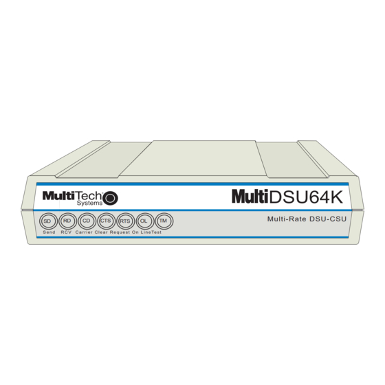
MT64DSU Owner's Manual Introduction Welcome to Multi-Tech's new MultiDSU64K a stand-alone integrated Data Service Unit (DSU), model number MT64DSU, for accessing 4- wire switched or dedicated digital links (Figure 1-1). The MultiDSU64K is a compact easy to operate unit with features allowing flexibility in meeting your transmission requirements. -
Page 7: About This Manual
Chapter 4 - Service, Warranty, Technical Support & BBS Chapter 4 provides instructions for getting MultiDSU64Ks serviced at the factory and information on product warranty; information about Multi-Tech's user Bulletin Board Service ( BBS ), receiving technical support via the CompuServe/Internet forums and information on Multi-Tech's Fax-Back Service. -
Page 8: Dsu Basic Functions
MT64DSU Owner's Manual DSU Basic Functions A DSU (Data Service Unit) and a CSU (Channel Service Unit) are typically connected to provide the interface between DTE (Data Terminal Equipment) and the DDS (Digital Data Service) or other four-wire networks. A DSU converts data to a bipolar format for transmission over the digital line. -
Page 9: Front Panel Indicators
Front Panel Indicators The MultiDSU64K has seven diagnostic LED indicators. They are: ® S e n d R C V C a r r i e r C l e a r R e q u e s t O n L i n e Te s t Transmit (Send) Data: This LED blinks when data is being transmitted, on for a space, off for a mark. -
Page 10: Back Panel
MT64DSU Owner's Manual Back Panel The cable connections for the MultiDSU64K are made at the back panel. The input data (DCE interface) is through either an RS-232 or V.35 connection; and, theDDS network connection is through an RJ48S line jack. -
Page 11: Features
Features Your Multi-Tech DSU/CSU provides the following features: • supports direct connection to the DATAPHONE Digital Data Service (DDS) or compatible network; • selectable sync speeds of 9600, 19200, 56000 for 4-wire lines and 64000 bps for 4-wire dedicated lines;... -
Page 12: Technical Specifications
MT64DSU Owner's Manual Technical Specifications • Interfaces RS-232C V.35 • Power Requirements • Temperature • Humidity • Dimensions • Weight • Certification • Compatibility • FIC Codes Digital Interface • USOC Jack • Modulation • Transmit Level • Output Impedance •... -
Page 13: Chapter 2 - Installation And Cabling
MultiDSU64K Chapter 2 - Installation and Cabling... -
Page 14: Introduction
MT64DSU Owner's Manual Introduction This chapter provides information for configuring and cabling the MultiDSU64K. It is assumed that the reader is familiar with the function and operation of data communications equipment and is technically qualified to provide installation service. Unpacking The shipping box contains the MultiDSU64K, an RJ48S line cord, a DSU Loopback cable, an AC Power Transformer and an Owner’s... -
Page 15: Chapter 2 - Installation And Connection
Cabling Procedure Installation of the MultiDSU64K includes making the proper cable connections and turning power on. LINE Figure 2-1. MultiDSU64K Back Panel Perform the following procedure to install your MultiDSU64K. Verify that the Dip-Switches on the MultiDSU64K are set for your particular configuration. -
Page 16: Dip Switch Settings
MT64DSU Owner's Manual DIP Switch Settings The MultiDSU64K printed circuit board contains one 12-position DIP-Switch block and one 4-position DIP-Switch block as shown in Figure 2-2. They are located on the side of the circuit board, and are accessible through the side of the chassis. Each individual switch is numbered, and can be in either an up (OPEN) or down (CLOSED) position. - Page 17 Switches #1 and #2 Speed Switches (Synchronous Mode) DIP-Switches #1 and #2 are used to set the synchronous data rate. Switches #1 and #2 are used in combination, to select the desired speed in your application. Note that first the asynchronous/ synchronous option must be chosen via DIP-Switch #5.
- Page 18 MT64DSU Owner's Manual DDS clocking (default) allows the MultiDSU64K to accept timing signals from the DDS network’s receive bipolar signal. Use this selection whenever the MultiDSU64K is connected to the DDS network lines. Internal Clocking External Clocking DDS Clocking (Factory Default Setting...
- Page 19 Switch #7 Data Set Ready "DSR" (Asynchronous/Synchronous Mode) When this option is enabled, the MultiDSU64K forces the DSR signal on continuously. The continuous DSR signal is used to eliminate momentary link interruptions that may be interpreted by the DTE as a communications channel failure. DSR controlled by DSU DSR Forced On (Factory Default Setting...
- Page 20 MT64DSU Owner's Manual Elastic Store Enabled Elastic Store Disabled (Factory Default Setting Switch #13 This switch must be in the DOWN position. Switch #14 Dedicated/Switched Line Operation (Asynchronous/Synchronous Mode) The MultiDSU64K works over either Dedicated or Switched lines. Note you must have this switch positioned in Switched Line mode (UP) in order to issue AT Commands.
-
Page 21: Chapter 3 - Testing
MultiDSU64K Chapter 3 - Testing... -
Page 22: Diagnostic Tests
Appendix B for cable description. Note: The DSU must be in 4-wire dedicated line mode to perform this test. Obtain a DSU Loopback cable (#45640100) from Multi-Tech, or assemble one. Refer to Appendix B for instructions on building the Loopback cable. -
Page 23: Local Loopback Test
Local Loopback Test This test allows you to test the local DTE and the local MultiDSU64K. Use the following steps to perform the Local Loopback Test. Set DIP-Switch #8 to the UP position. The front panel Test (TM) LED lights, and if you send data from your DTE, it should be “looped back”... -
Page 24: Digital Loopback Test
MT64DSU Owner's Manual Digital Loopback Test This test allows you to test the local DTE, the local MultiDSU64K, the communications link, and the remote MultiDSU64K. Use the following steps to perform the Digital Loopback Test. Set DIP-Switch #9 on the remote MultiDSU64K to the UP position. -
Page 25: Local Loopback Test With Test Pattern
Local Loopback Test With Test Pattern This test allows you to test the local MultiDSU64K. Perform the following steps to enable this test: Set DIP-Switch #8 to the UP position. Set DIP-Switch #11 to the UP position. The front panel (TM) LED lights, and if errors are detected, the Carrier Detect LED blinks. -
Page 26: Digital Loopback Test With Test Pattern Test
MT64DSU Owner's Manual Digital Loopback Test With Test Pattern Test This test allows you to test the local MultiDSU64K, the communications link, and the remote MultiDSU64K. Use the following steps to perform the Digital Loopback Test with the Pattern Test. -
Page 27: Remote Loopback Test
Remote Loopback Test This test allows you to test the local DTE, the local MultiDSU64K, the communications link, and the remote MultiDSU64K. Use the following steps to perform the Remote Loopback Test. Set DIP-Switch #10 on the local MultiDSU64K to the UP position. -
Page 28: Remote Loopback Test With Test Pattern Test
MT64DSU Owner's Manual Remote Loopback Test With Test Pattern Test This test allows you to test the local MultiDSU64K, the communications link, and the remote MultiDSU64K. Use the following steps to perform the Remote Loopback Test with the Pattern Test. -
Page 29: Dsu Back-To-Back Test
DSU operation. Using a DSU that is known to be operational, you can test a second DSU that is suspect. Obtain a DSU Back-to-Back cable (#45050000) from Multi-Tech, or assemble one. Refer to Appendix B for instructions on building the Back-to-Back cable. - Page 30 MT64DSU Owner's Manual...
-
Page 31: Chapter 4 - Warranty, Service And Tech Support
MultiDSU64K Chapter 4 - Warranty, Service and Tech Support... -
Page 32: Introduction
Fax-Back Service. Limited Warranty Multi-Tech Systems, Inc. ( “MTS” ) warrants that its products will be free from defects in material or workmanship for a period of two years from the date of purchase, or if proof of purchase is not provided, two years from date of shipment. -
Page 33: Tech Support
Tech Support Multi-Tech has an excellent staff of technical support personnel available to help you get the most out of your Multi-Tech product. If you have any questions about the operation of this unit, call 1-800- 972-2439. Please fill out the MultiDSU64K information (below), and have it available when you call. -
Page 34: Service
Information available from the BBS includes new product information, product upgrade files, and problem-solving tips. The phone number for the Multi-Tech BBS is (800) 392-2432 (USA and Canada) or (612) 785-3702 (international and local). The BBS can be accessed by any asynchronous modem operating at 1200 bps to 56 Kbps at a setting of 8 bits, no parity, and 1 stop bit (8-N-1). -
Page 35: To Log On To The Multi-Tech Bbs
Chapter 4 - Warranty, Services, and Tech Support To log on to the Multi-Tech BBS 1. Set your communications program to 8-N-1. 2. Dial our BBS at (800) 392-2432 (USA and Canada) or (612) 785-3702 (international and local). 3. At the prompts, type your first name, last name, password;... -
Page 36: About Compuserve
8. When completed, press ENTER to return to the File Menu. 9. To exit the BBS, type G and press ENTER. About CompuServe In addition to the BBS, Multi-Tech provides support through CompuServe's Modem Vendor Forum ( GOMODEMVEN ). Refer to your CompuServe documentation for special operating procedures. -
Page 37: About The Multi-Tech Fax-Back Service
Chapter 4 - Warranty, Services, and Tech Support About the Multi-Tech Fax-Back Service Multi-Tech’s fax-back system provides 24-hour access to sales, marketing, and technical literature. Dial 612-717-5888, follow the voice prompts, and request document number 10 for a catalog of available documents. - Page 38 MT64DSU Owner's Manual...
-
Page 39: Appendixes
MultiDSU64K Appendixes... -
Page 40: Appendix A - At Commands And S-Registers
MT64DSU Owner's Manual Appendix A - AT Commands and S-Registers Introduction AT commands are the means by which you, and your datacomm software, are able to communicate with and configure your MultiDSU64K. They enable you to establish, read, and modify parameters in addition to dialing. - Page 41 Action Commands Re-execute previous command (no AT prefix required with this command). DS n Dial a stored number ( n = 0 thru 9 memory location ). Ten phone numbers can be stored. D xxx Number of characters allowed in a telephone number string .
- Page 42 MT64DSU Owner's Manual S-Registers Certain configurations are stored in memory registers called, S-Registers. The S command is used to assign a value to, and to read the current value of an S-Register. To assign a value to an S- Register, enter the letter S , followed by the S-Register number and an equals sign ( = ).
- Page 43 S4 DCE Interface Mode S4 = 0 DCE Interface is Async S4 = 1 DCE Interface is Sync (Not Used) (Not Used) S7 Echo Canceler Tone S7 = 0 Echo Canceler Tone Disabled S7 = 1 Echo Canceler Tone Enabled S8 RTS Control S8 = 0 RTS On...
- Page 44 MT64DSU Owner's Manual S15 Async DTE Dialing S15 = 0 Disabled S15 = 1 DTR low-to-high Transition S15 = 2 AT Command S15 = 3 DTR or AT Command S16 V.25bis Auto-Dialing Format S16 = 0 Bit-oriented S16 = 1...
-
Page 45: Result Codes
Result Codes When the MultiDSU64K receives an AT command from the terminal or PC, the MultiDSU64K tries to execute the command, then sends a status message to the PC or terminal which reports the "results" of the command (hence the name "result codes" ). The MultiDSU64K provides you with several responses, or “Result Codes”... -
Page 46: Configuration Options
MT64DSU Owner's Manual Configuration Options This section describes the configuration parameters option settings. Corresponding S-Registers and AT commands are listed for each option or function. Synchronous Options If the MultiDSU64K is configured for synchronous operation (*S4=1), the following options apply: DTE Dialing (S2) - Selects the option for dialing synchronously. - Page 47 Appendixes DTE Dialing (S15) - Selects the type of asynchronous auto-dialing to be used by the DTE port. Options are AT Command, DTR (low- to-high), AT or DTR, and DISABLED. The factory default setting is AT Command--S15 = 2. Parameter Options The following options enable downloading of configurations parameters to a remote unit and the ability to lock a local unit to prevent local or remote changes to the configuration:...
-
Page 48: List Of Commands
MT64DSU Owner's Manual Synchronous Auto-Dial The beginning of this chapter described the AT command set which enables the MultiDSU64K to dial, hang-up, and be configured for various applications. These commands, however, are only functional when the DCE transmits asynchronous data. That is, the AT command set cannot be used in synchronous environments. - Page 49 Appendixes Clear Number in Memory (CLA) Command The CLA command clears a specific number in the nn phone number memory location by entering CLA nn . Dial Phone Number Stored in Memory (CRS) Command A telephone number that is stored in the DSU's memory may be automatically dialed.
- Page 50 MT64DSU Owner's Manual V.25bis Result Codes V.25bis Responses (Result Codes) When in V.25bis mode, your MultiDSU64K provides you with several responses which can help you follow the progress of V.25bis operations. These are similar to the Result Codes associated with AT Command mode operation.
-
Page 51: Appendix B - Application Examples
Appendixes Appendix B - Application Examples INTRODUCTION This section illustrates several types of applications in which the MultiDSU64K is typically used. These types include: • DDS point-to-point application, • DDS multipoint (polled) application, • Local Area Data Set, • External Clocking application, and •... - Page 52 MT64DSU Owner's Manual Multipoint DDS provides communication between a control station and two or more remote stations. All data transmitted by the control station is sent to each remote station. For data transmitted from the remote stations, the MJUs combine bit streams from the remote stations into a single, serial bit stream sent to the control station.
- Page 53 LOCAL AREA DATA SET APPLICATION Your MultiDSU64K can be used as a point-to-point LADS (Local Area Data Set) at transmission speeds of 2400, 4800, 9600, 19200, 56000 or 64000 bps over 4-wire, non-loaded metallic wire pairs. The installation of the MultiDSU64K in a LADS application is the same as for DDS applications, except for the timing (Clocking) setting.
- Page 54 MT64DSU Owner's Manual EXTERNAL CLOCKING APPLICATION This application is similar to the Local Area Data Set application except for the timing option setting. In the example below, the DTE connector of the T1 mux is connected to the DTE connector of the MultiDSU64K.
- Page 55 Appendixes The analog modem at the same end as the MultiDSU64K must have External Timing enabled; the modem at the end of the off-net extension must have DDS Timing enabled. In MultiDSU64K applications that use controlled carrier, the CTS delay for the analog modem at the end of the off-net extension must be longer than the CTS delay of the MultiDSU64K.
-
Page 56: Appendix C - Interface Signals And Connector Pinouts
MT64DSU Owner's Manual Appendix C - Interface Signals and Connector Pinouts DDS RJ48S CONNECTOR Figure C-1. RJ48S Connection DESCRIPTION This connector ties the MultiDSU64K to the DDS Network. PIN IDENTIFICATION Description Transmit Receive Pin 1 Pin 8 As viewed from the rear... - Page 57 RS-232C DB25S CONNECTOR Figure C-2. RS-232 Connection DESCRIPTION This connector ties the MultiDSU64K to the DTE. The DB25S connector has the following pinout configuration. PIN IDENTIFICATION Description Transmit Data Received Data Request to Send RTS Clear To Send Data Set Ready DSR Signal Ground Carrier Detect Test Voltage...
- Page 58 MT64DSU Owner's Manual V.35 34-PIN CONNECTOR Signal Designation Chassis Ground Request To Send Data Set Ready Data Terminal Ready Send Data (A) Send Data (B) Terminal Timing (A) Terminal Timing (B) Send Timing (A) Send Timing (B) DESCRIPTION This connector ties the MultiDSU64K to the DTE. The V.35 connector has the following pinout configuration.
-
Page 59: Build Instructions
It tests the DSU by having the DSU generate a signal, then the cable “loops” the signal back to the DSU for comparison to the original signal sent. You can order this cable (#45640100) from Multi-Tech, or build one using the instructions below. SCHEMATIC RJ48S BUILD INSTRUCTIONS Strip cable insulation 3/4"... - Page 60 DSU. It tests the suspect DSU by connecting its Transmit signal to the good DSUs Receive circuits. You can order it from Multi-Tech (#45050000), or build one using the instructions below. Refer to Chapter 4 for test procedures. SCHEMATIC...
-
Page 61: Crossover Cable
Appendixes CROSSOVER CABLE Figure C-6. Crossover Cable In applcations using the MULTIDSU64K for an off-net extension a “cross-over” cable is required to connect the MultiDSU64K DCE connector to the analog modem in this application. -
Page 62: Appendix D - Dip-Switch Summary
MT64DSU Owner's Manual Appendix D - DIP-Switch Summary Synchronous DIP-Switch Asynchronous DIP-Switch *Factory Default Setting Effect Sync Speeds 9.6K 19.2K Internal External DDS Asynchronous Mode On Synchronous Mode On RTS Controlled by DTE RTS Forced On DSR Controlled by DSU... -
Page 63: Appendix E - Fcc Regulations For Telephone Line Interconnection
Appendix E - FCC Regulations for Telephone Line Interconnection This equipment complies with Part 68 of the Federal Communications Commission (FCC) rules. On the outside surface of this equipment is a label that contains, among other information, the FCC registration number and ringer equivalence number (REN). - Page 64 MT64DSU Owner's Manual If trouble is experienced with this equipment (see model indicated below) please contact Multi-Tech Systems, Inc. at the address shown below for details on how to have repairs made. If the trouble is causing harm to the telephone network, the telephone company may request you remove the equipment from the network until the problem is resolved.
-
Page 65: Index
Index About This Manual 7 Action Commands 41 ANALOG OFF-NET EXTENSION APPLICATION 54 Analog Off-Net Extension Applica- tion 55 Application Examples 51 Async data bits 43 Async DTE Dialing 44 Asynchronous/Synchronous Opera- tion 18 Auto-Answer 42 Auto-Disconnect 42 Back-to Back Cable 60 Basic DSU/CSU Configuration 8 Certification 12 Clear Number in Memory (CLA) - Page 66 MT64DSU Owner's Manual Limited Warranty On-line Warranty Registration 32 Listing Numbers Stored in Memory (RLN) Command 49 Local Area DataA Set Application 53 Loopback Cable 59 Model Number 11 Modulation 12 MultiDSU64K Back Panel 14, 15 MultiDSU64K PC Circuit Board 16...
Need help?
Do you have a question about the MT64DSU and is the answer not in the manual?
Questions and answers