Table of Contents
Advertisement
Quick Links
Advertisement
Table of Contents

Related Manuals for Multitech MultiDSU MTT1DSU


Summary of Contents for Multitech MultiDSU MTT1DSU
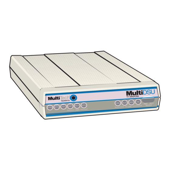
- Page 1 Model MTT1DSU User Guide...
- Page 2 Class A Manual Declaration NOTE: This equipment has been tested and found to comply with the limits for a Class A digital , pursuant to Part 15 of the FCC Rules. These limits are designed to provide reasonable protection against harmful interference when the equipment is operated in a commercial environ- ment.
- Page 3 Furthermore, Multi-Tech Systems, Inc. reserves the right to revise this publication and to make changes from time to time in the content hereof without obligation of Multi-Tech Systems, Inc. to notify any person or organization of such revisions or changes.
-
Page 4: Table Of Contents
Chapter 1 - Introduction and Description Introduction ... 8 About This User Guide ... 9 Front Panel ... 10 Back Panel ... 11 LINE Connector ... 11 COMMAND Connector ... 11 Data Connector ... 11 POWER Connector ... 11 FCC Regulations for Telephone Line Interconnection ... 12 Specifications ... - Page 5 Put Remote Into Loop Back ... 44 Processor Loopback ... 44 Chapter 6 - Warranty, Service and Technical Support Introduction ... 46 Limited Warranty ... 46 On-line Warranty Registration ... 47 Service ... 47 About the Internet ... 48 About the Multi-Tech Fax-Back Service ... 48...
-
Page 7: Chapter 1 - Introduction And Description
Chapter 1 - Introduction and Description... - Page 8 Introduction The Multi-Tech Systems MultiDSU (Model number MTT1DSU) is a low cost, full-featured T1-FT1 Data Service Unit (DSU). The MultiDSU provides an interface between point-to-point T1 or Fractional T1 service and the end user's Data Terminal Equipment (DTE). This unit also provides Facility Data Link (FDL) support.
-
Page 9: About This User Guide
About This User Guide This user guide describes the MultiDSU and explains how to install and configure the unit. The information contained in each chapter is as follows: Chapter 1 - Introduction and Description Chapter 1 describes the MultiDSU and provides a review of this user guide. -
Page 10: Front Panel
Front Panel The front panel contains three sets of LEDs that provide the status of the MultiDSU and its data and T1 connections. The Data LEDs display the status and activity of the V.35 Data port. The T1 Line LEDs show whether the T1 Line is online or in a failure mode. -
Page 11: Back Panel
Back Panel All the cable connections for the MultiDSU are made at the back panel. The Line connector enables the MultiDSU to be connected to a T1 line from the local Telco central office (CO). The Command connector is used to configure the MultiDSU using a PC or terminal. -
Page 12: Fcc Regulations For Telephone Line Interconnection
FCC Regulations for Telephone Line Interconnection 1.This equipment complies with Part 68 of the Federal Communications Commission (FCC) rules. On the outside surface of this equipment is a label that contains, among other information, the FCC registration number and ringer equivalence number (REN). - Page 13 6. If trouble is experienced with this equipment (the model of which is indicated below) please contact Multi-Tech Systems, Inc. at the address shown below for details of how to have repairs made. If the trouble is causing harm to the telephone network, the telephone company may request you remove the equipment from the network until the problem is resolved.
-
Page 14: Specifications
Specifications T1 Line • Single T1 Line port with synchronous data format • AMI or B8ZS line coding • D4 Superframe or Extended Superframe framing support • 1 to 24 channels at 56 kbps or 64 kbps each • T1 line connector is an RJ48 jack Data Port •... -
Page 15: Chapter 2 - Installation
Chapter 2 - Installation... -
Page 16: Introduction
Inspect the contents for signs of any shipping damage. If damage is observed, do not power up the unit, contact Multi-Tech's Technical Support for advice (refer to Chapter 6 - Warranty, Service and Technical Support). If no damage is observed, remove all items from the box, place the MultiDSU in its final location, and connect your cables and power supply. -
Page 17: Multidsu Configuration
MultiDSU Configuration Configuring the MultiDSU involves completing all the necessary connections, including connecting a cable between the MultiDSU and your DTE device, connecting your PC or terminal to the command port, connecting the point-to-point T1 line or back-to-back cable and power, setting up the PC or terminal to configure the MultiDSU, and finally configuring the MultiDSU using the Configuration procedure provided in this chapter. - Page 18 LAN 1 Router Workstation Server Data Port MultiDSU (Master) RJ48 back-to-back connection (with T1 crossover cable) Data Port MultiDSU (Slave) Router Server Workstation LAN 2 Figure 2-2. DSX-1 Short Haul Application (0 < 655 Feet)
-
Page 19: Cabling Your Multidsu
Cabling Your MultiDSU Cabling your MultiDSU involves making the proper Power, Command port, Line, and Data port connections. Figure 2-2 shows a typical application for the MultiDSU. Figure 2-3 shows the back panel connec- tors and associated cable connections, and Table 2-1 contains the procedures for connecting the cables to your MultiDSU. - Page 20 4. Connect the external wall transformer power supply to the MultiDSU and plug it into a live AC outlet. When power is applied to the unit and the on/off switch is set to the up ("1" or On) position, the front panel LEDs will light. 5.
-
Page 21: Configuration
Configuration If you are connecting to a Telco, get the following T1 information from your Telco : Line Code: AMI/B8ZS__________________________________ Framing Format: D4/ESF________________________________ Available bandwidth: Full T1 (24 DS0s), or Number of DS0s and which DS0 assignments, if FT1. _________ If you are using your MultiDSU as a short-haul modem, select the identical line coding and framing format to be used in both units. - Page 22 3. Enter option 1 and press the ENTER key to display the T1 Line Configuration menu with options for Framing Format, Line Coding, and Line Type and Length. T1 Line Configuration 1. Framing Format 2. Line Coding 3. Line Type and Length Enter Selection (-(previous), q(uit), <1>): _ If any of these default selections (shown) are incorrect for your particular application, enter the corresponding option number to...
- Page 23 Line Coding 1. Alternate Mark Inversion (AMI) 2. Binary 8 Zero Substitution (B8ZS) Enter Selection (-(previous), q(uit), <1>): _ Enter option 2 and press the ENTER key if you need to switch from the default AMI to B8ZS. You will then see the new selection displayed on the T1 Line Configuration menu.
- Page 24 Configurations 1. T1 Line Configuration 2. DS0 Speed/DS0 Allocation 3. Clocking 4. V.35 Port 5. Set configurations 6. Set and Save configurations 7. Reset to Factory Defaults Enter Selection (-(previous), q(uit), <1>): _ 5. At the Configurations menu, enter option 2 and press the ENTER key to display the DS0 Speed/DS0 Allocation menu.
- Page 25 Configurations 1. T1 Line Configuration 2. DS0 Speed/DS0 Allocation 3. Clocking 4. V.35 Port 5. Set configurations 6. Set and Save configurations 7. Reset to Factory Defaults Enter Selection (-(previous), q(uit), <1>): _ 9. At the Configurations menu, enter option 3 and press the ENTER key to display the current selection (Internal, Line, or External).
- Page 26 10. At the configurations menu, enter option 4 and press the ENTER key to display the RTS/DTR menu associated with the V.35 Data Port. V.35 Port 1. Force RTS Enter Selection (-(previous), q(uit), <1>): _ 11.To toggle RTS from "Independent" to "Forced," enter option number 1, then press the ENTER key and select 2 (for Forced) and press the ENTER key.
- Page 27 T1 DSU Main Menu 1. Configurations 2. Current Status 3. Statistics 4. Diagnostics 5. System Information Enter Selection (-(previous), q(uit), <1>): _...
-
Page 29: Chapter 3 - Menu System
Chapter 3 - Menu System... -
Page 30: Introduction
Introduction The menu system for the MultiDSU provides a set of user-friendly configuration menus that are accessible from a main menu. The Main Menu contains four options that enable you to configure your MultiDSU, check the current operating status, display hourly and daily statistics, or run diagnostic tests;... -
Page 31: Framing Format
T1 Line Configuration 1. Framing Format 2. Line Coding 3. Line Type and Length Enter Selection (-(previous), q(uit), <1>): _ Framing Format The MultiDSU supports two types of framing formats: D4 Superframe (D4) and Extended Superframe (ESF). The D4 Superframe option (option 1) is a 193-bit frame format in which the 193rd bit has framing and signaling information. -
Page 32: Line Type And Length
Line Type and Length The line type and line length options enable the user to configure the MultiDSU to match the characteristics of the T1 line. The default selection is CSU (0db) or DSX-1 (0-133ft). CSU is a long haul line type that allows the DSX-1 signal to be transmitted up to 6000 ft at Line Build Out (LBO) options of 0 dB, -7.5 dB, -15 dB, or -22.5 dB. -
Page 33: Clocking Menu
Clocking Menu This menu enables you to select the clock timing (Internal, Line, or External) for the MultiDSU. If you are connecting to a Telco, choose option 2, "Line." For a back-to-back setup, set one unit for Internal (option 1) (or External, option 3, if your DTE is providing the 1.544 MHz clock) and set the other unit for Line (option 2). -
Page 34: Reset To Factory Defaults
menu. Once they are saved, these settings will be retained if the MultiDSU happens to lose power or is turned Off. Reset to Factory Defaults The Configurations menu also enables you to reset the MultiDSU to the factory defaults by selecting option 7 and pressing the ENTER key. Current Status Screen Selecting option 2 on the Main Menu displays the Current Status screen which displays the line status, receive level range, and the... -
Page 35: Statistics
Statistics Selecting option 3 on the Main Menu displays the Statistics. This screen enables you to view any of eight different types of hourly or daily statistics. The Hourly Statistics are displayed first, followed by the Daily Statistics. From these performance data you can produce reports for the previous 24 hours in 15-minute increments. -
Page 36: Bursty Errored Secs
Bursty Errored Secs Bursty Errored Seconds (BES) are seconds containing 2 to 319 CRC6 errors. Severely Errored Secs Severely Errored Seconds (SES) are seconds with 320 or more CRC6 errors. Failed Secs Failed Seconds are seconds that failed due to one or more errors. Controlled Slips Controlled Slips (CS) occur when the receiving device either replicates or deletes a DS1 frame. -
Page 37: Diagnostics
Diagnostics Selecting option 4 on the Main Menu opens the Diagnostics screen, with options for the various types of loopback tests that can be per- formed when a T1 crossover cable is connected between the LINE jacks on two MultiDSUs. The loopback tests are discussed in detail in Chapter 5 - Diagnostics. -
Page 38: System Information
System Information Selecting option 5 on the Main Menu opens the System Information screen, which displays the firmware version number. System Information Firmware Version Press <Return> to continue: _ : Version 1.00... -
Page 39: Chapter 4 - Remote Configuration
Chapter 4 - Remote Configuration... -
Page 40: Introduction
Introduction Remote configuration of the MultiDSU involves using modems to communicate from the local PC or terminal to the remote MultiDSU, where a special Remote Configuration Cable is used to link the receiv- ing modem to the Command port of the MultiDSU. Modem-Based Remote Configuration Procedure 1. -
Page 41: Chapter 5 - Diagnostics
Chapter 5 - Diagnostics... -
Page 42: Introduction
Introduction MultiDSU diagnostics involve using the Diagnostics menus that are accessible through option 4 on the Main Menu. Option 4 opens the Diagnostics Menu that enables you to run loopback diagnostic tests on the MultiDSU and its connecting lines. Setup for Diagnostic Loopback Tests Connect a T1 crossover cable between the LINE jacks on two MultiDSUs. -
Page 43: Diagnostics Menu
Diagnostics Menu The Diagnostics menu enables you to run (and end) any of four different loopback tests, return to the previous menu, or exit (quit) the command mode. Diagnostics 1. Local Loop Back 2. Remote Loop Back 3. Processor Loop Back 4. -
Page 44: Put Remote Into Loop Back
Remote Loopback MultiDSU Figure 5-2. Remote Loopback Test Processor Loopback This test (option 3 on the Diagnostics menu) loops back the data in the MultiDSU's Central Processor Unit (CPU) and assures that the CPU and the T1 transceiver are communicating correctly. See Figure 5-3. Processor Loopback MultiDSU Figure 5-3. -
Page 45: Chapter 6 - Warranty, Service And Technical Support
Chapter 6 - Warranty, Service and Technical Support... -
Page 46: Introduction
(BBS), and get support through the Internet. Limited Warranty Multi-Tech Systems, Inc. (“MTS”) warrants that its products will be free from defects in material or workmanship for a period of two years from the date of purchase, or if proof of purchase is not provided, two years from date of shipment. -
Page 47: On-Line Warranty Registration
If your tech support specialist decides that service is required, your MultiDSU may be sent (freight prepaid) to our factory. Return shipping charges will be paid by Multi-Tech Systems. Include the following with your MultiDSU: • a description of the problem. -
Page 48: About The Internet
About the Internet Multi-Tech is a commercial provider on the Internet. If you prefer to receive service via the internet, you can contact Tech Support via e-mail at the following address: http://www.multitech.com/support Multi-Tech's presence includes a Web site at: http://www.multitech.com and an ftp site at: ftp://ftp.multitech.com... - Page 49 Appendixes...
-
Page 50: Appendix A - Cabling Diagrams
Appendix A - Cabling Diagrams Command Port Cable PIN NO. To COMMAND Port Jack Line Cable LINE 1 2 3 4 5 6 7 8 RJ48 Jack Signal Name Receive Ring Receive Tip Transmit Ring Transmit Tip COMMAND 1 2 3 4 5 6 7 8 PIN NO. -
Page 51: Data Cable
Data Cable... - Page 52 82083200...
Need help?
Do you have a question about the MultiDSU MTT1DSU and is the answer not in the manual?
Questions and answers