Table of Contents
Advertisement
Quick Links
Advertisement
Table of Contents

Subscribe to Our Youtube Channel
Related Manuals for Multitech MT56DSU2


Summary of Contents for Multitech MT56DSU2
- Page 1 MT56DSU2 Owner’s Manual MultiDSU56K Model MT56DSU2 Owner’s Manual 82017502...
- Page 2 Furthermore, Multi-Tech Systems, Inc. reserves the right to revise this publication and to make changes from time to time in the content hereof without obligation of Multi-Tech Systems, Inc. to notify any person or organization of such revisions or changes. Record of Revisions...
-
Page 3: Table Of Contents
MT56DSU2 Owner’s Manual CHAPTER 1-INTRODUCTION AND DESCRIPTION 1.1 Introduction 1.2 About This Manual 1.3 Description 1.4 CSU/DSU Basics 1.5 Features 1.6 FCC Regulations for Telephone Line Interconnection 1.7 Specifications CHAPTER 2- HARDWARE INSTALLATION 2.1 Introduction 2.2 Default DIP Switch Settings 2.3 Changing Default Settings... -
Page 4: Chapter 1-Introduction And Description
MT56DSU2 Owner’s Manual Chapter 1 - Introduction and Description 1.1 Introduction Congratulations! Your new MultiDSU56K is one of the finest DSU/CSUs available today. As a combined CSU (Channel Service Unit) and DSU (Data Service Unit), it provides a direct connection to the DATAPHONE ® Digital Service (DDS) network. The MultiDSU56K connects a computer or Data Terminal Equipment (DTE) to remote equipment using DDS network lines at 2400, 4800, 9600, 19200 and 56000 bps speeds for point-to-point and multi-point service. -
Page 5: Dsu Functions
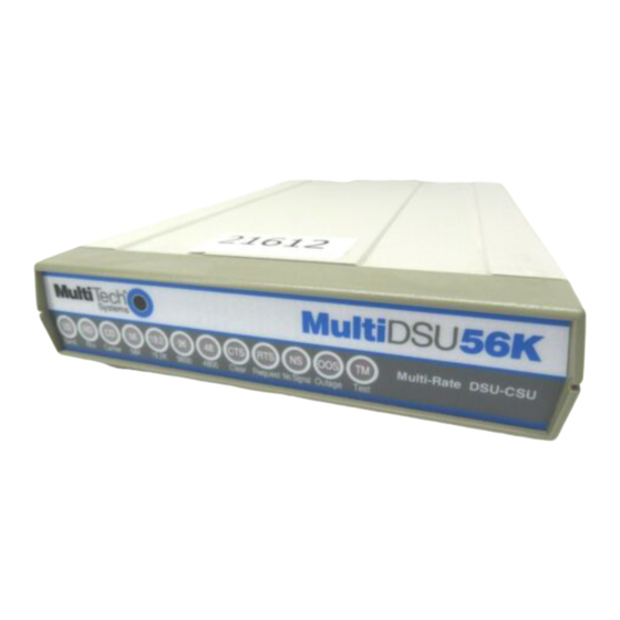
9600 4800 Clear Request NoSgnl Outage Test Figure 1-1. Multi-Tech System’s MultiDSU56K 1.4 CSU/DSU Basics A DSU (Data Service Unit) and a CSU (Channel Service Unit) are typically connected to provide the interface between DTE (data terminal equipment) and the DDS (Digital Data Service) or other four-wire network. -
Page 6: Features
MT56DSU2 Owner’s Manual 1.5 Features The MultiDSU56K provides many useful features. Standard features include V.35 and RS232 connections and either synchronous or asynchronous transmission; synchronous at rates up to 56000 bps and asynchronous up to 19200 bps; selectable digital rates that match the services offered by the carriers. -
Page 7: Fcc Regulations For Telephone Line Interconnection
7. No repairs are to be made by you. Repairs are to be made only by Multi-Tech Systems or its licensees. Unauthorized repairs void registration and warranty. -
Page 8: Specifications
MT56DSU2 Owner’s Manual 1.7 Specifications Model Number MT56DSU2 Device Operation combined DSU and CSU Data Rates Synchronous: 2400, 4800, 9600, 19200, 56000 bps Asynchronous: 2400, 4800, 9600, 19200 bps Interfaces RS232C DB25S (female) V.35 34-pos. rectangular (female) RJ48 8-position keyed jack... - Page 9 MT56DSU2 Owner’s Manual Delay Times (in secs.): RTS/CTS DCD on DCD off 2400 4800 9600 19200 56000 82017502...
-
Page 10: Chapter 2- Hardware Installation
MT56DSU2 Owner’s Manual Chapter 2 – Hardware Installation 2.1 Introduction This chapter provides the information needed to configure and install the MultiDSU56K. This manual assumes the reader is familiar with the function and operation of data communications equipment and is technically qualified to provide installation service. - Page 11 MT56DSU2 Owner’s Manual The Mu11iDSU56K DIP switches are shown and described below. Figure 2-1 MuIttDSU56K Board Layout 2.2.1 12-Position DIP Switch (#1-12) The 12-position DIP switch is used to select the data rate, clocking, RTS control, DSR control, AsynclSync operation, diagnostic modes (Loopback Test, Test Pattern), Circuit Assurance, and System Status. The default settings are shown in Table 2-1.
- Page 12 MT56DSU2 Owner’s Manual An adhesive-backed label containing the DIP switch setting information is provided on the bottom of the MultiDSU56K; a sample label is shown below for reference. 82017502...
- Page 13 MT56DSU2 Owner’s Manual The factory default settings are indicated by an * in table 2-1. Table 2-1. MuII1DSU56K Switch Settings Switch Description Data Rate (in bps) 2400 4800 9600 Down Down Down Down Up* Down Down Down Down Clocking Internal...
-
Page 14: Installation Procedure
MT56DSU2 Owner’s Manual 2.4 Installation Procedure Installation of the MultiDSU56K includes making cable connections to the back panel and turning power on. The MultiDSU56K back panel is shown below. Figure 2-2. MultiDSU56K Back Panel Perform the steps below to install the MultiDSU56K. -
Page 15: Chapter 3- Operation
MT56DSU2 Owner’s Manual 3.1 Introduction This chapter provides information on the operating functions of the MultiDSU56K. During normal operation the MultiDSU56K requires no operator intervention. Many of the optional features of the MultiDSU56K are selected by setting a DIP switch on the PC board. -
Page 16: Elastic Store
Notes for off-net (elastic store enabled) sites: • a special DCE-DCE cross-over cable is required (not supplied by Multi-Tech). • the modem located with the MultiDSU56K must be set for external timing. The modem located at the far end of the off-net extension must be set for slave timing. -
Page 17: Rts Forced On
MT56DSU2 Owner’s Manual 3.2.8 RTS Forced On With this option enabled, the MultiDSU56K provides a continuous CTS signal, disregarding the state of the RTS signal at the DTE interface connector. This will provide a continuous outbound indication to the network and remote (far-end) device that there is a “Carrier on” condition. -
Page 18: Off-Net Extension Applications
MT56DSU2 Owner’s Manual The MultiDSU56K uses 4-wire non-loaded metallic circuits for LADS applications. The table below outlines approximations for the maximum cable length for limited distance applications. Data Rate 2400 bps 4800bps 9600 bps 19200bps 56000 bps Note that line characteristics will vary depending on cable type/manufacturer, splices, bridge taps, etc. -
Page 19: Chapter 4- Troubleshooting
MT56DSU2 Owner’s Manual Chapter 4 - Troubleshooting 4.1 Introduction All of the indicators used in normal operation of the MultiDSU56K are on the front panel. Each front panel LED is labeled, as explained below. The LEDs provide status and maintenance information on the MultiDSU56K, as well as the attached network and line. -
Page 20: Indicator
MT56DSU2 Owner’s Manual 4.2.6 96 Indicator The 96 LED lights when the “Data Rate” selection is set at 9600 bps. This indicator will be off for all other data rates. Refer to Chapter 2 for switch settings. 4.2.7 48 Indicator The 48 LED lights when the “Data Rate”... -
Page 21: Local Loopback Test
MT56DSU2 Owner’s Manual 4.3.1 Local Loopback Test This test allows you to test the local DTE and the local MultiDSU56K. Use the following steps to perform the Local Loopback Test. 1. Set DIP switch #9 to the down position. 2. The front panel Test (TM) LED lights, and if you send data from your DTE, it should be “looped back”... -
Page 22: Digital Loopback Test With Test Pattern Test
MT56DSU2 Owner’s Manual 4.3.3 Digital Loopback Test With Test Pattern Test This test allows you to test the local MultiDSU56K, the communications link, and the remote MultiDSU56K. Use the following steps to perform the Digital Loopback Test with the Pattern Test. -
Page 23: Dsu Loopback Test
This test lets you verify proper DSU operation by matching a transmitted signal to the “looped- back” receive signal. Refer to Appendix B for cable description. 1. Obtain a DSU Loopback cable (#45640100) from Multi-Tech, or assemble one. Refer to Appendix B for instructions on building the Loopback cable. -
Page 24: Dsu Back-To-Back Test
Using a DSU that is known to be operational, you can test a second DSU that is suspect. 1. Obtain a DSU Back-to-Back cable (#45050000) from Multi-Tech, or assemble one. Refer to Appendix B for instructions on building the Back-to-Back cable. -
Page 25: Chapter 5- Service, Warrantyand Tech Support
To register your DSU on-line, go to: Tech Support Multi-Tech has an excellent staff of technical support personnel available to help you get the most out of your Multi-Tech product. If you have any questions about the operation of this unit, call 1-800-972-2439. - Page 26 MT56DSU2 Owner’s Manual If you need to inquire about the status of the returned product, be prepared to provide the serial number of the product sent . Send DSUs to: MULTI-TECH SYSTEMS, INC. 2205 WOODALE DRIVE MOUNDS VIEW, MINNESOTA 55112...
-
Page 27: Appendix A - Application Examples
MT56DSU2 Owner’s Manual Appendix A - Application Examples INTRODUCTION This section illustrates several types of applications in which the MultiDSU56K is typically used . These types include: • DDS point-to-point application, • DDS multipoint (polled) application, • Local Area Data Set, •... - Page 28 MT56DSU2 Owner’s Manual DDS MULTIPOINT (POLLED) APPLICATION Since your Central Office (CO) equipment must include “Multipoint Junction Units” (MJU5) and other special arrangements for this type of service, you may need to coordinate efforts with your network service provider. The MultiDSU56K at the host end is the Master Station (also called the “Control Station”), which typically has RTS forced on.
- Page 29 MT56DSU2 Owner’s Manual LOCAL AREA DATA SET APPLICATION In this application, two pairs of wires provide the connection between two MultiDSU56K devices. The two pairs can be up to the equivalent of 3 miles of 26 AWG wire at 56000 bps, or longer for subrate applications (see distances chart in section 3.4.1 of this manual).
- Page 30 MT56DSU2 Owner’s Manual ANALOG OFF-NET EXTENSION APPLICATION In this application, the MultiDSU56K is used with conventional analog modems and lines to complete DDS circuits in an area where DDS is not available (Site #3 in the example below) or where the customer requires an extension of the DDS circuit for a special application.
-
Page 31: Appendix B - Interface Signals And Connector Pinouts
MT56DSU2 Owner’s Manual Appendix B - Interface Signals and Connector Pinouts As viewed from the rear DESCRIPTION This connector ties the MultiDSU56K to the DDS Network. The RJ48 connector is keyed for proper insertion of a keyed RJ48 plug. PIN IDENTIFICATION... - Page 32 MT56DSU2 Owner’s Manual RS232C DB25S CONNECTOR Transmitter Signal — Element Timing Receive Clock (RC) — Transmit Clock (TC) — As viewed from the rear DESCRIPTION This connector ties the MultiDSU56K to the DTE. The DB25S connector has the following pinout configuration.
- Page 33 MT56DSU2 Owner’s Manual V.35 34-PIN CONNECTOR Signal Designation Chassis Ground Request To Send Data Set Ready Data Terminal Ready Send Data (A) Send Data (B) Terminal Timing (A) Terminal Timing (B) Send Timing (A) Send Timing (B) DESCRIPTION This connector ties the MultiDSU56K to the DTE. The V.35 connector has the following pinout configuration.
- Page 34 DSU generate a signal, then the cable “loops” the signal back to the DSU for comparison to the original signal sent. You can order this cable (#45640100) from Multi-Tech, or build one using the instructions below. Refer to Chapter 4 for test procedures.
- Page 35 This cable lets you test a suspect DSU by connecting it to a known good DSU. It tests the suspect DSU by connecting its Transmit signal to the good DSUs Receive circuits. You can order it from Multi-Tech (# 45050000), or build one using the instructions below. Refer to Chapter 4 for test procedures.
-
Page 36: Glossary
MT56DSU2 Owner’s Manual Glossary This section defines several of the terms used in this manual. For an overview of DSU basics, refer to section 1.4 of this manual. ALBO (Automatic Line Build Out) — part of the “equalizer” circuitry used to compensate for various gauges and alterations of local loops. - Page 37 MT56DSU2 Owner’s Manual Data Communications Equipment (DCE) — equipment that provides the function to establish, maintain and terminate a connection. Additionally, provides the signal conversion required for communications between DTE and data circuit or telephone line. See also “DTE”. DDS (Dataphone Digital Service) — AT&Ts private-line end-to-end digital service, with data rates (typically) at 2400, 4800, 9600, 19200, and 56000 bps.
- Page 38 MT56DSU2 Owner’s Manual master station — see “control station”. MJU (Multipoint Junction Unit) — a digital data bridge, located at telco office, for the DDS network. Used to combine remote station’s bit streams into one serial bit stream for transmission to the control station.
- Page 39 MT56DSU2 Owner’s Manual test pattern — a diagnostic test for sending ,detecting and checking a pre-defined pattern of bits. two-wire circuit — A circuit in which one channel (line) is used for communications in both directions. Contrast ‘Iour-wire circuit”. 82017502...
Need help?
Do you have a question about the MT56DSU2 and is the answer not in the manual?
Questions and answers