Bioness NESS L300 User Manual
Foot drop system
Hide thumbs
Also See for NESS L300:
- Clinicians manual (131 pages) ,
- User manual (85 pages) ,
- User reference manual (2 pages)
Table of Contents
Advertisement
Quick Links
Manufactured by Bioness Neuromodulation Ltd.
A Bioness Inc Company
19 Ha'Haroshet Street
PO Box 2500
Industrial Zone
Ra'Anana 43654, Israel
Worldwide Corporate Office
Bioness Inc
25103 Rye Canyon Loop
Valencia, CA 91355 USA
Telephone: 800-211-9136
Email: info@bioness.com
Website: www.bioness.com
European Authorized Representative
NESS Europe B.V.
Stationsweg 41
3331 LR Zwijndrecht, The Netherlands
Telephone: +31.78.625.6088
Email: international@nl.bioness.com
Website: www.bioness.com
NESS
, NESS L300
, Intelli-Gait
®
®
registered trademarks of Bioness Inc. in the United States or other countries | www.bioness.com
Rx Only (U.S. Only)
612-00061-001 Rev D
01/2013
, Intelli-Sense Gait Sensor™, Bioness, the Bioness Logo® and LiveOn
®
are
®
Advertisement
Table of Contents

Related Manuals for Bioness NESS L300


Summary of Contents for Bioness NESS L300
- Page 1 , NESS L300 , Intelli-Gait , Intelli-Sense Gait Sensor™, Bioness, the Bioness Logo® and LiveOn ® ® ® ® registered trademarks of Bioness Inc. in the United States or other countries | www.bioness.com Rx Only (U.S. Only) 612-00061-001 Rev D 01/2013...
- Page 2 NESS L300 ® User’s Guide...
- Page 3 User’s Guide...
- Page 4 Disclaimer Bioness Inc and its affiliates shall not be liable for any injury or damage suffered by any person, either directly or indirectly, as a result of the unauthorized use or repair of Bioness Inc products. Bioness Inc does not accept any responsibility for any damage caused to its products, either directly or indirectly, as a result of use and/or repair by unauthorized personnel.
-
Page 5: Table Of Contents
Control Unit Operating Modes ..............24 Control Unit Digital Display and Indicator Lights ......... 24 Control Unit Audio Indicators ............... 26 Chapter 6: Setting Up the NESS L300 System ........27 Positioning the FS Cuff ..................27 Removing the FS Cuff ..................30... - Page 6 Chapter 7: Operating the NESS L300 ..........35 RF Communication Safety Features ..............35 Operating the Control Unit ................. 35 Turning On/Off the Control Unit ..............35 Selecting an Operating Mode ..............36 Adjusting Stimulation Intensity ..............37 Adjusting the Volume of Audio Alerts ............37 Turning On Audio Feedback During Stimulation ..........
-
Page 7: List Of Symbols
List of Symbols Caution Complies with United States and Canadian Product Safety Standards Complies with the European Union Medical Device Directive Serial Number Double Insulated (Equivalent to Class II of IEC 536) Type BF Applied Part(s) Non-Ionizing Radiation European Authorized Representative Date of Manufacture Manufacturer This Product Must not be Disposed of with Other Household Waste... -
Page 9: Chapter 1: Introduction
The NESS L300 Foot Drop System is an advanced neuroprosthesis designed to improve gait in people suffering from foot drop. The NESS L300 incorporates cutting-edge technology and sophisticated design features to improve walking and quality of life. - Page 10 The wireless hand-held Control Unit monitors system status and manages system performance. Your clinician has prescribed the NESS L300 Foot Drop System to treat your foot drop. This User’s Guide describes your NESS L300 Foot Drop System and how to operate your system to achieve maximum benefits. Be sure to read this guide before using your NESS L300.
-
Page 11: Chapter 2: Health And Safety Information
The NESS L300 should not be used where a cancerous lesion is present or suspected. • The NESS L300 should not be used on a leg where a regional disorder, such as a fracture or dislocation, could be adversely affected by motion from the stimulation. -
Page 12: Precautions
RF Stim Unit. • Do not use the NESS L300 within three feet of short wave or microwave therapy equipment. Such equipment may produce instability in the RF Stim Unit output. - Page 13 • Do not wear the NESS L300 during x-ray examinations. • Turn off the NESS L300 when at a refueling place. Do not use the NESS L300 near flammable fuel, fumes, or chemicals. • Only your treating clinician should determine electrode placement and stimulation settings.
-
Page 14: Adverse Reactions
It should not be worn by anyone else or on any other part of the body. • Turn off the NESS L300 before putting on the FS Cuff. Do not turn on the NESS L300 until the FS Cuff is fastened in place. -
Page 15: Skin Care Guidelines
FS Cuff. Skin irritation tends to occur after approximately three months of use. To promote healthy skin with long-term use of the NESS L300, it is important to follow a daily skin-care routine. - Page 16 Caution: Do not put on or operate the NESS L300 before being properly fitted and trained by a certified clinician. Caution: The Intelli-Sense Gait Sensor has not been validated for use by individuals weighing more than 136 kilograms (300 pounds).
-
Page 17: Chapter 3: Environmental Conditions That Affect Use
Environmental Conditions that Affect Use Radio Frequency (RF) Communication Several components of the NESS L300 communicate via radio communication and have been tested and found to comply with the limits for a Class B digital device, pursuant to Part 15 (RF Devices) of the FCC (Federal Communications Commission) Rules. -
Page 18: Travel
NESS L300. The NESS L300 will likely set off the security alarm. Either ask for a “hand scan” or be prepared to remove your NESS L300 so that security can scan it. - Page 19 NESS L300 System. • The NESS L300 System should not be used adjacent to or stacked with other equipment. If adjacent or stacked use is necessary, the equipment or system should be observed to verify normal operation in the configuration in which it will be used.
- Page 20 • The NESS L300 System may be interfered with by other equipment, even if that other equipment complies with CISPR (International Special Committee on Radio Interference, International Electrotechnical Commission (IEC)) emission requirements. 12 User’s Guide...
-
Page 21: Chapter 4: Ness L300 System Kit
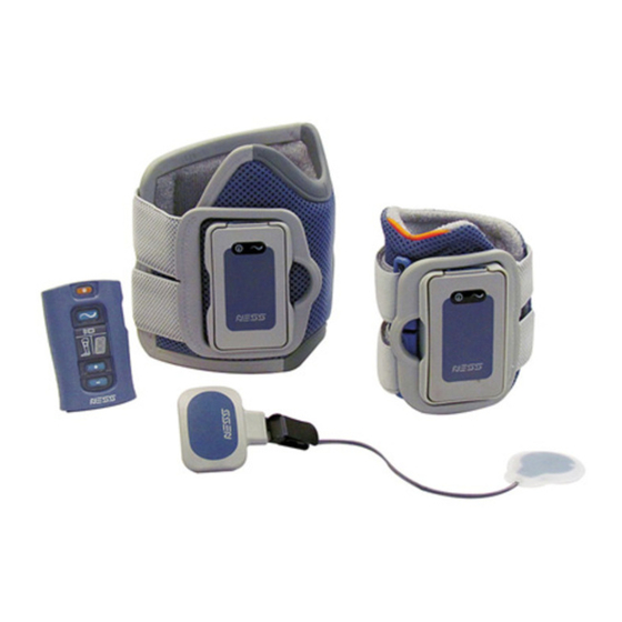
NESS L300 System Kit Your Small NESS L300 System Kit includes the following: • Small L300 FS Cuff, Right or Left, with (XS) Strap • L300 RF Stim Unit • Intelli-Sense Gait Sensor • Control Unit • System Charger Set •... - Page 22 Your Regular NESS L300 System Kit includes the following: • Regular L300 FS Cuff, Right or Left, with (M) Strap • L300 RF Stim Unit • Intelli-Sense Gait Sensor • Control Unit • System Charger Set • Regular L300 FS Cuff Strap (S) •...
- Page 23 Small L300 FS Cuff and RF Stim Unit and RF Stim Unit Intelli-Sense Gait Sensor Control Unit System Charger Set Regular FS Cuff Strap Small FS Cuff Strap (S, M, L) (XXS, XS) Chapter 4 - NESS L300 System Kit...
- Page 24 Gait Sensor Pads Shoe Spacers Phillips Screwdriver Small Electrode Bases Gait Sensor (only in the Small NESS Replacement Battery Cloth Electrode Mesh Bag L300 System Kit) Control Unit Neck Strap Control Unit Wrist Strap Control Unit Belt Pouch 16 User’s Guide...
-
Page 25: Chapter 5: Ness L300 System Components
Electrode Liner Liner Locator Locator Strap Strap Strap Handle Handle Cradle RF Stim Unit Regular L300 FS Cuff Small L300 FS Cuff Figure 5-1: Regular L300 FS Cuff and Small L300 FS Cuff. Chapter 5 - NESS L300 System Components... -
Page 26: Electrodes And Electrode Bases
Electrodes and Electrode Bases There are three types of electrodes that can be used with the L300 FS Cuff to deliver stimulation. With a Small NESS L300 System the following electrodes and electrode bases can be used (See Figure 5-2): •... - Page 27 With a Regular NESS L300 System the following electrodes and electrode bases can be used (See Figure 5-3): • Regular L300 Quick Fit Electrode, left - A or right - A • Regular L300 Cloth Electrodes • Regular L300 Cloth Electrode Bases •...
-
Page 28: Rf Stim Unit
RF Stim Unit The RF Stim Unit fits into the cradle of the L300 FS Cuff. See Figure 5-1. It responds to signals from the Control Unit and Intelli-Sense Gait Sensor to turn stimulation on/off. It has a rechargeable battery, a status light, and a stimulation light. -
Page 29: Intelli-Sense Gait Sensor
Intelli-Sense Gait Sensor The Intelli-Sense Gait Sensor detects when your foot is in the air and on the ground, and wirelessly signals the other NESS L300 components to move your foot accordingly. The Intelli-Sense Gait Sensor features a pressure sensor and a transmitter. The pressure sensor fits under the insole of the shoe of your weak foot, attached to a Gait Sensor pad. -
Page 30: Control Unit
Control Unit communicates wirelessly with the RF Stim Unit and Intelli-Sense Gait Sensor. It is powered by a single rechargeable AAA battery. Your NESS L300 System Kit includes a system charger set for charging the Control Unit and RF Stim Unit. It also includes a belt pouch, wrist strap, and neck strap for carrying the Control Unit. -
Page 31: Control Unit Operating Buttons
Mode Training, or Clinician Mode Adjusts Volume of Audio Volume Alerts and Turns On/Off Audio Feedback for Stimulation Intensity Adjusts Stimulation Intensity Adjustment Level (Plus/Minus) Table 5-2: Control Unit operating buttons and functions. Chapter 5 - NESS L300 System Components... -
Page 32: Control Unit Operating Modes
The Control Unit has four operating modes: standby, gait, training, and clinician. Only clinicians use clinician mode. Standby Mode In standby mode, the NESS L300 System is on and waiting for commands. Stimulation is off. Gait Mode Gait mode is used when walking. In gait mode, the Gait Sensor signals the RF Stim Unit when your heel or forefoot leaves the ground, turning stimulation on. - Page 33 Training Mode Digital Display A Component Component Low Indicator Flashes Battery YELLOW Rotating GREEN Control Unit Charging Circle Horizontal GREEN Control Unit Fully Line Charged Table 5-3: Control Unit visual displays and definitions. Chapter 5 - NESS L300 System Components...
-
Page 34: Control Unit Audio Indicators
Control Unit Display Description Definition RF Stim Unit Indicator Faulty Electrode Flashes RED and Contact Intensity Level Flashes Control Unit and RF Radio Communication Stim Unit Indicators Failure Between the Alternately Flash RED Control Unit and RF and “E” Flashes Stim Unit Gait Sensor Gait Sensor and RF... -
Page 35: Chapter 6: Setting Up The Ness L300 System
(Place your foot on a footrest, if necessary.) The Locator of the FS Cuff Fits Under the Kneecap Figure 6-1: Recommended knee angle for positioning the L300 FS Cuff. Chapter 6 - Setting Up the NESS L300 System... - Page 36 4. Make sure the electrodes are securely attached. Then, grasp the front of the L300 FS Cuff by the cradle and tilt the bottom of the FS Cuff up. Slide the locator up your leg until it rests snugly and comfortably below your kneecap.
- Page 37 Figure 6-3: Fastening the L300 FS Cuff strap. Locator Below the Kneecap RF Stim Unit Strap Handle Around the Cradle Regular L300 FS Cuff Small L300 FS Cuff Figure 6-4: L300 FS Cuff fastened on the right leg. Chapter 6 - Setting Up the NESS L300 System...
-
Page 38: Removing The Fs Cuff
Removing the L300 FS Cuff To remove the L300 FS Cuff: 1. Turn off the Control Unit. 2. Unhook the L300 FS Cuff strap handle from the cradle. 3. Slowly lift the L300 FS Cuff away from your skin. 4. If using hydrogel electrodes (Regular L300 FS Cuff users only) gently peel the electrodes from your skin, and reapply the electrode covers to the electrodes. -
Page 39: Positioning The Intelli-Sense Gait Sensor
2. Attach a Gait Sensor pad under the insole, in the position that was defined by your clinician. See Figure 6-5. Shoe Insole Gait Sensor Pad Gait Sensor Pad Heel Position Forefoot Position Figure 6-5: Placement of the Gait Sensor pad. Chapter 6 - Setting Up the NESS L300 System... - Page 40 3. For heel position placement point the wire of the Intelli-Sense Gait Sensor toward the toe of the shoe. For forefoot position placement point the wire of the Intelli-Sense Gait Sensor toward the heel of the shoe. Then, attach the pressure sensor to the Gait Sensor pad. See Figure 6-6. Refer to the foot image on the pressure sensor for positioning.
- Page 41 6. Cover the pressure sensor with the insole. Tuck any excess wire under the insole. See Figure 6-9. Heel Position Forefoot Position Figure 6-9: Insole covering the pressure sensor and wire. (Left shoe shown.) Chapter 6 - Setting Up the NESS L300 System...
- Page 42 Switching Shoes/Gait Sensors When switching the Intelli-Sense Gait Sensor to a different shoe, make sure to place a Gait Sensor pad in the other shoe first. If multiple Gait Sensors are placed in multiple shoes and you want to switch shoes: 1.
-
Page 43: Chapter 7: Operating The Ness L300
The Control Unit and RF Stim Unit indicators will flash RED and “E” will flash in the digital display. • The Control Unit will emit an audio alert. The NESS L300 will deliver a warning default stimulation to lift the foot • for six seconds before shutting down. Operating the Control Unit... -
Page 44: Selecting An Operating Mode
Selecting an Operating Mode Gait Mode. To select gait mode, turn on the Control Unit, and press the mode button briefly. The Control Unit will beep and the mode button will start flashing YELLOW SLOWLY (indicating that stimulation is off). When stimulation is on, the mode button will flash YELLOW RAPIDLY. -
Page 45: Adjusting Stimulation Intensity
To mute the audio alerts, lower the volume to the lowest setting. When the system is turned off, the active volume level is saved. If the active volume level is “mute”, the default volume level is automatically restored. Chapter 7 - Operating the NESS L300... -
Page 46: Turning On Audio Feedback During Stimulation
Turning On Audio Feedback During Stimulation You can choose to receive an audio alert when stimulation turns on. To turn on Audio Feedback, turn on the Control Unit and press and hold the volume button for three seconds. To turn off Audio Feedback, press the down volume adjust button or turn off the Control Unit. -
Page 47: Chapter 8: Maintenance And Cleaning
Maintenance and Cleaning Charging the Batteries When a system component has a low battery, the Control Unit will beep and the component indicator light will flash YELLOW. See Table 8-1. When the RF Stim Unit battery is low, the RF Stim Unit status light will also flash YELLOW. - Page 48 To charge the batteries in the Control Unit and RF Stim Unit: 1. Open and assemble the System Charger Set. The System Charger set comes with four interchangeable blades for U.S. and international outlets. Select the appropriate blade that fits the chosen power outlet and slide the blade onto the end of the charger.
- Page 49 Caution: Do not use the RF Stim Unit or Control Unit while charging. Caution: Use only the charger included in your NESS L300 System Kit. Use of any other charger could damage the system. 3. Connect the system charger set to the Control Unit and RF Stim Unit.
- Page 50 Note: It is possible to charge the Control Unit and RF Stim Unit separately, but Bioness recommends that the Control Unit and RF Stim Unit be charged at the same time. 6. The charging process will continue until a horizontal GREEN line appears in the Control Unit digital display and the RF Stim Unit status light is solid GREEN.
-
Page 51: Replacing The Batteries
Replacing the Batteries RF Stim Unit Battery The RF Stim Unit rechargeable battery should be replaced approximately every two years by a Bioness certified technician. Intelli-Sense Gait Sensor Battery The battery in the Intelli-Sense Gait Sensor is not rechargeable. It should be replaced approximately every six months. -
Page 52: Control Unit Battery
2. Slide the cover out. 3. Note the “+” orientation of the old battery. 4. Remove the old battery and properly dispose of it according to your local environmental regulations. 5. Insert the new battery. The “+” should face outward. 6. - Page 53 4. Insert the new rechargeable battery in the proper "+/-" orientation. 5. Slide the cover into place, and tighten the screw. 6. Fully charge the new battery before first use. Caution: Use of a non-rechargeable AAA battery can damage the Control Unit. Battery Cover Screw Battery...
-
Page 54: Replacing The L300 Quick Fit Electrodes
Caution: Use only L300 electrodes supplied by Bioness. Caution: Do not use your NESS L300 system without electrodes. Caution: Do not fold or twist the L300 Quick Fit Electrode. To replace the L300 Quick Fit Electrodes: (See Figure 8-7) 1. - Page 55 Orange and Blue Plug Holes Figure 8-7: Replacing the L300 Quick Fit Electrode. (Regular L300 Quick Fit Electrode and Regular L300 FS Cuff shown.) Chapter 8 - Maintenance and Cleaning...
-
Page 56: Replacing The Cloth Electrodes
Caution: Use only L300 cloth electrodes supplied by Bioness. Caution: Do not use your NESS L300 system without electrodes. To replace the L300 Cloth Electrodes: (See Figure 8-8) 1. Turn off the Control Unit and remove the L300 FS Cuff.. - Page 57 Note: Store the L300 Cloth Electrodes, when not in use in the Cloth Electrode Mesh Bag or in a location where they can air dry. Figure 8-8: Replacing the L300 Cloth Electrodes. (Regular L300 Cloth Electrodes and Regular L300 FS Cuff shown.) Chapter 8 - Maintenance and Cleaning...
-
Page 58: Replacing The Hydrogel Electrodes
Caution: Use only L300 hydrogel electrodes supplied by Bioness. Caution: Do not use your NESS L300 System without electrodes. To replace the L300 Hydrogel Electrodes: (See Figure 8-9) 1. Turn off the Control Unit and remove the L300 FS Cuff.. - Page 59 Note: Save the covers. Always reapply the covers between uses. When reapplying the covers, make sure the Bioness logo faces up. Note: If the electrode gel becomes dry, rehydrate it with one to two drops of water. Figure 8-9: Replacing the L300 Hydrogel Electrodes. (Regular L300 Hydrogel Electrodes and Regular L300 FS Cuff shown.)
-
Page 60: Replacing The Electrode Bases
Replacing the Electrode Bases You will need to replace the electrode bases after one year of use. Contact Bioness to purchase replacement electrode bases. For Regular L300 FS Cuff users, if you are switching from hydrogel to cloth electrodes, or from cloth electrodes to hydrogel electrodes, you will need to be seen by a qualified clinician for a first fitting. - Page 61 Plug Hole Figure 8-10: Replacing the L300 Electrode Bases. (Regular L300 FS Cuff shown.) Chapter 8 - Maintenance and Cleaning...
-
Page 62: Removing The Rf Stim Unit
Removing the RF Stim Unit The only time you should remove the RF Stim Unit is to clean the FS Cuff or replace the RF Stim Unit. To remove the RF Stim Unit: 1. Turn off the Control Unit. 2. Pull the top of the RF Stim Unit away from the cradle. See Figure 8-11. If the fit is too tight, open the flexible cover over the charging port for a better grasp. -
Page 63: Cleaning Your Ness L300 Components
Cleaning Your NESS L300 Components All NESS L300 components may be cleaned by carefully wiping them with a damp cloth. The electrical components are not waterproof. Do not immerse them in water. The L300 FS Cuff is the only component that can be immersed in water to clean. - Page 64 56 User’s Guide...
-
Page 65: Chapter 9: Electronically Registering New Components
Bioness. Then, place it at least 30 feet from the NESS L300 components you are registering. 4. Make sure all other NESS L300 components are at least 9.14 meters (30 feet) from the NESS L300 components you are registering. Chapter 9 - Electronically Registering New Components... - Page 66 Figure 9-1: Registration setup. Registration 1. Turn off the new Control Unit. 2. Simultaneously press and hold for three seconds the mode and minus buttons. The Control Unit will beep when registration begins. 3. The Control Unit digital display will show two alternating GREEN arches while registration is in process.
- Page 67 Error Figure 9-2: Registration digital displays. 6. After registration is complete, turn on your NESS L300 System. If the new Control Unit is registered, the RF Stim Unit will turn on. If you see an RF failure indication between the Control Unit and RF Stim Unit, wait 20 minutes for the RF Stim Unit to enter energy-saving mode, and then repeat the registration procedure.
-
Page 68: Registering A New Rf Stim Unit
Caution: Do not turn on the Control Unit, if the RF Stim Unit is not in the cradle. 3. Put the old RF Stim Unit in an envelope for shipment to Bioness. Place it at least 30 feet from the components you are registering. - Page 69 Unit, and the Intelli-Sense Gait Sensor close to each other on a table but not touching. 8. Make sure all other NESS L300 components are at least 9.14 meters (30 feet) from the NESS L300 components you are registering. Registration 1.
-
Page 70: Registering A New Intelli-Sense Gait Sensor
2. Place the new Intelli-Sense Gait Sensor, L300 FS Cuff with RF Stim Unit, and Control Unit close together on a table but not touching. 3. Make sure all other NESS L300 components (including the used Intelli- Sense Gait Sensor in your shoe) are at least 9.14 meters (30 feet) from the components you are registering. - Page 71 YELLOW rapidly for four seconds. 7. Locate the System ID Number on the NESS L300 carrying case (for example, A334). Write the number on the small label on the back of the new Intelli-Sense Gait Sensor. See Figure 9-6. This number identifies which system the sensor is registered to.
- Page 72 Blank Label Figure 9-6: Label on the Intelli-Sense Gait Sensor for the System ID Number. 64 User’s Guide...
-
Page 73: Chapter 10: Troubleshooting
No. Daily charging will not affect the lifespan or functionality of the batteries. Daily charging is recommended. While charging, "E" appears in the digital display. • An error occurred while charging. Reconnect the system charger set. If the problem persists, contact Bioness. Chapter 10 - Troubleshooting... - Page 74 Stimulation works in training mode but not in gait mode. When I turn on gait mode I hear a beep, the RF Stim Unit and Gait Sensor indicators on the Control Unit alternately flash RED, and “E” flashes in the digital display. •...
- Page 75 I hear a beep, the RF Stim Unit indicator on the Control Unit flashes RED, and the stimulation intensity level flashes in the Control Unit digital display. If you feel stimulation but the intensity level seems weaker than usual and ankle movement is unsatisfactory, electrode contact may be compromised.
- Page 76 • The respective component is malfunctioning. Turn off the Control Unit and turn it back on. If the problem persists, then stop using the NESS L300 system and contact Bioness. One of the component indicators is flashing YELLOW. • The respective component battery charge level is low. Charge or replace the battery.
- Page 77 My skin is irritated or has a skin reaction where the electrodes or L300 FS Cuff adheres. • Stop using the NESS L300 system immediately and contact your clinician, dermatologist, or local distributor. Resume use only when the skin is completely healed. Ask your clinician or dermatologist for a skin conditioning protocol.
- Page 78 I tried the registration procedure and saw a “C” immediately, but I never saw the alternating arches in the digital display. The replacement component is not working. • Clinician mode (for use by clinicians only) may have been started instead of the registration process. Clinician mode is started by pressing the minus on/off buttons on the Control Unit.
-
Page 79: Chapter 11: Technical Specifications
Technical Specifications Control Unit Specifications Classification Internally powered, continuous operation Operation Modes Gait, Training, Clinician, and Standby Battery Type Rechargeable AAA NiMH 1.2 V, 900–1100 mAh On/Off illuminated button Mode illuminated button for changing operating modes Controls Intensity +/- buttons to fine-tune intensity level Volume buttons to adjust volume of audio alerts Three status LEDs: Control Unit, RF Stim Unit, and Intelli- Sense Gait Sensor... - Page 80 RF Stim Unit Specifications Internally powered, continuous operation with type BF Classification applied parts Operating 3.7 V Voltage Battery Type Proprietary rechargeable Li-Ion (Lithium Ion) 3.7 V, 700 mAh Status (fault, battery, charging) and Stimulation LEDs Indications “Beeps” for audio alerts Length: 74 mm (2.9 in.) Dimensions Width: 43 mm (1.7 in.)
- Page 81 Symmetric Asymmetric Positive Pulse Duration (µsec) Negative Pulse 1200 Duration (µsec) Inter-Phase Interval (µsec) Total Pulse 1000 1500 Duration (µsec) Max Load 5000 ohm (Subject to max voltage limitation) Pulse 20–45 Hz, 5-Hz resolution Repetition Rate Gait Parameters Ramp Up 0–2 seconds, 0.1-second resolution Ramp Down 0–2 seconds, 0.1-second resolution...
- Page 82 FS Cuff Specifications Regular L300 FS Cuff Small L300 FS Cuff Material Fabric-Polymer Fabric-Polymer Fits Limb 29–51 cm (11–20 in.) 22–31 cm (8-12.2 in.) Circumference Height: 160 mm (6.3 in.) Height: 110.5 mm (4.5 in.) Dimensions Width: 100 mm (3.9 in.) Width: 80 mm (3 in.) Depth: 125 mm (4.9 in.) Depth: 100 mm (4 in.)
- Page 83 Power Supply Specifications Use medical Class II safety approved power supply provided/approved by Bioness with the following ratings: Input Voltage 100–240 V AC Current 400 mA Frequency 50–60 Hz Output Voltage 5 V ± 5% Current 2400 mA Note: Do not use the Control Unit or RF Stim Unit while charging.
- Page 84 Two, 45-mm (1.77-in.) diameter, surface area 15.8 cm Regular hydrogel electrodes Hydrogel Electrodes Note: Use only electrodes provided by Bioness Inc Regular Hydrogel Two relocatable polymer electrode bases for individual fitting Electrode Bases Two, 45-mm (1.77-in.) diameter, surface area 15.8 non-woven polymer fabric (80% viscose, 20% polypropylene);...
- Page 85 Two, 36-mm (1.41-in.) diameter, surface area 10.1 cm² hydrogel electrodes Small Hydrogel Electrodes Use only for fitting process Note: Use only electrodes provided by Bioness Inc Small Electrode Two, 36-mm (1.41-in.) diameter, relocatable Thermoplastic Bases elastomer (TPE) electrode bases Two, 36-mm (1.41-in.) diameter, surface area 10.1cm non- woven polymer fabric (80% viscose, 20% polypropylene);...
- Page 86 78 User’s Guide...
-
Page 87: Chapter 12: Appendix - Emi Tables
Appendix - EMI Tables System Characteristics Transmitters Operating Frequency Band 2401–2482 MHz Type of Modulation Type of Modulating Signal Binary data message Data Rate [=Frequency of Modulating 250 Kbps Signal] Effective Radiated Power <10 dBm Receivers Operating Frequency Band 2401–2482 MHz Receiver Bandwidth 812 kHz around a selected frequency Chapter 12 - Appendix - EMI Tables... - Page 88 Guidance and Manufacturer’s Declaration—Electromagnetic Emissions The NESS L300 System is intended for use in the electromagnetic environment specified below. The customer or the user of the NESS L300 System should assure that it is used in such an environment. Emissions Test Compliance Electromagnetic Environment –...
- Page 89 All Equipment and Systems The NESS L300 System is intended for use in the electromagnetic environment specified below. The customer or the user of the NESS L300 System should assure that it is used in such an environment. Electromagnetic...
- Page 90 Electromagnetic IEC 60601 Test Compliance Immunity Test Environment – Level Level Guidance Voltage dips, short <5% U (>95% dip <5% U (>95% dip Mains power interruptions and in U ) for 0.5 cycle in U ) for 0.5 cycle quality should be voltage variations that of a typical on power supply...
- Page 91 Guidance and Manufacturer’s Declaration—Electromagnetic Immunity The NESS L300 System is intended for use in the electromagnetic environment specified below. The customer or the user of the NESS L300 System should assure that it is used in such an environment. Immunity...
- Page 92 To assess the electromagnetic environment due to fixed RF transmitters, an electromagnetic site survey should be considered. If the measured field strength in the location in which the NESS L300 System is used exceeds the applicable RF compliance level above, the NESS L300 System should be observed to verify normal operation.
- Page 93 Recommended Separation Distances Between Portable and Mobile RF Communications Equipment and the NESS L300 System The NESS L300 System is intended for use in an electromagnetic environment in which radiated RF disturbances are controlled. The customer or the user of the...
- Page 94 NOTE 1: At 80 MHz and 800 MHz, the higher frequency range applies. NOTE 2: These guidelines may not apply in all situations. Electromagnetic propagation is affected by absorption and reflection from structures, objects, and people. For transmitters rated at a maximum output power not listed above, the recommended separation distance d in meters (m) can be determined using the equation applicable to the frequency of the transmitter, where P is the maximum output power rating of the transmitter in watts (W) according to the transmitter manufacturer.
Need help?
Do you have a question about the NESS L300 and is the answer not in the manual?
Questions and answers