Bioness NESS L300 User Manual
Foot drop system
Hide thumbs
Also See for NESS L300:
- Clinicians manual (131 pages) ,
- User manual (94 pages) ,
- User reference manual (2 pages)
Table of Contents
Advertisement
Quick Links
Advertisement
Table of Contents

Related Manuals for Bioness NESS L300


Summary of Contents for Bioness NESS L300
- Page 1 NESS L300 ® User’s Guide...
- Page 2 Disclaimer Bioness Inc. and its affiliates shall not be liable for any injury or damage suffered by any person, either directly or indirectly, as a result of the unauthorized use or repair of Bioness Inc. products. Bioness Inc. does not accept any responsibility for any damage caused to its products, either directly or indirectly, as a result of use and/or repair by unauthorized personnel.
-
Page 3: List Of Symbol
List of Symbols Caution Warning Double Insulated (Equivalent to Class II of IEC 536) Type BF Applied Part(s) Non-Ionizing Radiation Date of Manufacture Manufacturer This Product Must Not Be Disposed of with Other Household Waste Refer to Instruction Manual/ Booklet Re-Order Number Lot Number Serial Number... -
Page 4: Table Of Contents
Table of Contents List of Symbol ....................iii Chapter 1: Introduction ................ 1 Chapter 2: Safety Information .............. 3 Indications for Use ..................... Contraindications ....................Warnings ......................Precautions ......................Adverse Reactions .................... Skin Care Guidelines ..................Chapter 3: Environmental Conditions that Affect Use ....... 9 Radio Frequency (RF) Communication ............. - Page 5 Attaching the Electrodes ..................27 L300 Quick Fit Electrode ................27 L300 Cloth Electrodes ................. 28 L300 Hydrogel Electrodes ................29 Positioning the L300 FS Cuff ................30 Removing the L300 FS Cuff ................32 Positioning the Intelli-Sense Gait Sensor ............32 Chapter 7: Operating the L300 System ..........
- Page 6 Inserting the RF Stim Unit ................. 49 Cleaning Your L300 System Components ............50 Disinfecting ......................51 Chapter 9: Electronic Registration of Replacement ....53 Registering a New Control Unit ................. 53 Registering a New RF Stim Unit ................ 55 Registering a New Intelli-Sense Gait Sensor ............
- Page 7 User’s Guide...
-
Page 8: Chapter 1: Introduction
They often drag their foot, resulting in instability and increased effort during gait. The NESS L300 Foot Drop System is an advanced neuroprosthesis designed to improve gait in people suffering from foot drop. The L300 System incorporates cutting-edge technology and sophisticated design features to improve walking and quality of life. - Page 9 L300 System. Be sure to review this guide with your clinician. If you have any questions contact the Bioness Client Relations Department at (800) 211-9136, Option 3 (in the United States) or your local distributor (outside of the United States). You can also visit the Bioness website at: www.bioness.com.
-
Page 10: Chapter 2: Safety Information
During the swing phase of gait, the NESS L300 electrically stimulates muscles in the affected leg to provide dorsiflexion of the foot. The NESS L300 may improve gait, facilitate muscle re-education, prevent or retard disuse atrophy, maintain or increase joint range of motion, and increase local blood flow. -
Page 11: Precautions
• In case of any inconvenience, turn off stimulation and remove the L300 FS Cuff. If the stimulation cannot be turned off, remove the L300 FS Cuff to stop stimulation. Precautions • Inflammation in the region of the L300 FS Cuff may be aggravated by motion, muscle activity, or pressure from the L300 FS Cuff. - Page 12 -20°C to +60°C (-4°F to +140°F). Temperature extremes can damage the components. • Do not attempt to repair your L300 System. Contact Bioness if you experience a technical problem not covered in this guide. • The L300 FS Cuff is to be worn only on the leg of the patient for whom it is fitted. It should not be worn by anyone else or on any other part of the body.
-
Page 13: Adverse Reactions
• Medical electrical equipment needs special precautions for electromagnetic compatibility. • Remove the L300 System before undergoing any diagnostic or therapeutic medical procedure such as x-ray examination, ultrasound, MRI, etc. Adverse Reactions In the unlikely event that any of the following occurs, stop using your L300 System immediately and consult your physician. - Page 14 If skin irritation or a skin reaction occurs, stop using your L300 System immediately and contact your clinician or dermatologist. Also contact the Bioness Client Relations Department: (800) 211-9136, Option 3 (in the United States) or your local distributor (outside the United States).
- Page 15 User’s Guide...
-
Page 16: Chapter 3: Environmental Conditions That Affect Use
Environmental Conditions that Affect Use Radio Frequency (RF) Communication Several components of the L300 System communicate via radio communication and have been tested and found to comply with the limits for a Class B digital device, pursuant to Part 15 (RF Devices) of the Federal Communications Commission (FCC) Rules. These limits are designed to provide reasonable protection against harmful interference in a residential installation. -
Page 17: Travel
The L300 System was tested and certified to use the following: • DC power supply as provided by Bioness Inc, manufactured by Friwo, Part No. FW7555M/05. • "Y" cable (2-way splitter) as provided by Bioness Inc. Manufactured by Tamuz Electronics Ltd. -
Page 18: Chapter 4: L300 System Kit
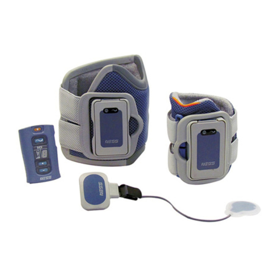
L300 System Kit Contents Small L300 System Kit • Small L300 FS Cuff, Right or Left, with (XS) Strap • L300 RF Stim Unit • Intelli-Sense Gait Sensor • Control Unit • System Charger Set • Small L300 FS Cuff Strap (XXS) •... - Page 19 Regular L300 System Kit • Regular L300 FS Cuff, Right or Left, with (M) Strap • L300 RF Stim Unit • Intelli-Sense Gait Sensor • Control Unit • System Charger Set • Regular L300 FS Cuff Strap (S) • Regular L300 FS Cuff Strap (L) •...
- Page 20 Regular L300 FS Cuff Small L300 FS Cuff and RF Stim Unit and RF Stim Unit Intelli-Sense Gait Sensor Control Unit System Charger Set Regular FS Cuff Strap Small FS Cuff Strap (S, M, L) (XXS, XS) Chapter 4 - L300 System Kit...
- Page 21 Gait Sensor Pads Shoe Spacers Phillips Screwdriver Small Electrode Bases Gait Sensor Replacement (only in the Small L300 Battery Cloth Electrode Mesh Bag System Kit) Control Unit Neck Strap Control Unit Wrist Strap Control Unit Belt Pouch User’s Guide...
-
Page 22: Chapter 5: Device Description
Device Description L300 Functional Stimulation (FS) Cuff The L300 FS Cuff (see Figure 5-1) is an orthosis that fits on the leg below the knee and is designed to facilitate upward movement of the foot and toes. The L300 FS Cuff is available in right and left configurations and in two sizes. - Page 23 when radio communication fails or the component malfunctions. The RF Stim Unit should only be removed from the cradle for maintenance and when cleaning the L300 FS Cuff. RF Stim Unit Display Description Definition Flashes Green System is On Status Light Flashes Yellow Low Battery Alternately Flashes...
-
Page 24: Electrodes And Electrode Bases
Electrodes and Electrode Bases There are three different types of electrodes that can be used with the L300 FS Cuff to deliver stimulation. The electrodes adhere to electrode bases, which snap onto the L300 FS Cuff liner. With a Small L300 System the following electrodes and electrode bases can be used (See Figure 5-2): •... - Page 25 Your clinician will fit you with the appropriate electrode option and attach them to your L300 FS Cuff. Afterward, you will need to replace the electrodes every two weeks. Caution: Use only the electrodes supplied by Bioness Inc. Caution: Do not use the L300 System without the electrodes attached to the FS Cuff.
-
Page 26: Intelli-Sense Gait Sensor
Intelli-Sense Gait Sensor The Intelli-Sense Gait Sensor detects when your foot is in the air and on the ground, and wirelessly signals the other L300 System components. The Intelli-Sense Gait Sensor features a pressure sensor and a transmitter. See Figure 5-4. The pressure sensor fits under the insole of your shoe. -
Page 27: Control Unit
Control Unit The Control Unit is used to turn on/off the system, select an operating mode, fine-tune stimulation intensity, adjust audio alert volume, and monitor system performance. See Figure 5-5. The Control Unit communicates wirelessly with the RF Stim Unit and Intelli- Sense Gait Sensor. -
Page 28: Operating Buttons
Gait Mode Gait mode is used when walking. In gait mode, the Intelli-Sense Gait Sensor signals the RF Stim Unit when your heel or forefoot leaves the ground, turning stimulation on. It also signals when your heel or forefoot contacts the ground, turning stimulation off. Training Mode Training mode is used to train muscles when you are not walking (for example, sitting or lying down). -
Page 29: Digital Display And Indicator Lights
Visual Display Description Function On/Off Button Flashes Green System On System is in Gait/Training/ Mode Button Flashes Yellow Slowly Clinician Mode, Stimulation is Off System is in Gait/Training/ Mode Button Flashes Yellow Rapidly Clinician Mode, Stimulation is On Table 5-3: Control Unit Operating Button Visual Displays Digital Display and Indicator Lights The Control Unit digital display and indicator lights indicate stimulation intensity level, operating mode, battery charge status, electronic registration status, and error messages. -
Page 30: Audio Indicators
Indicator Display Description Definition A Component Indicator Flashes Yellow Component Has Low Battery RF Stim Unit Indicator Flashes Red Faulty Electrode and Intensity Level Flashes Control Unit and RF Stim Unit Radio Communication Failure Indicators Alternately Flash Red and Between the Control Unit and RF "E"... - Page 31 User’s Guide...
-
Page 32: Chapter 6: Setup Instructions
Charging the L300 System It is important to charge your L300 System daily and for at least four hours before a fitting/ programming session. Bioness recommends charging the Control Unit and L300 FS Cuff (with RF Stim Unit attached) at the same time. - Page 33 Flexible Cover RF Stim Unit Charging Port Y Cable Flexible Cover Control Unit Charging Port System Charger Set Figure 6-3: Charging Setup 4. Plug the System Charger into a power outlet. 5. While charging a rotating green circle will appear in the Control Unit digital display and the status light on the RF Stim Unit will alternately flash yellow and green.
-
Page 34: Preparing The Skin
2. If necessary, trim excess body hair from the area using scissors. Do not use a razor. A razor can irritate the skin. Attaching the Electrodes Caution: Use only the L300 electrodes supplied by Bioness. Caution: Do not use your L300 System without the electrodes attached. L300 Quick Fit Electrode To attach the L300 Quick Fit Electrode to the L300 FS Cuff: 1. -
Page 35: L300 Cloth Electrodes
Figure 6-4: Wetting the Removing Excess Water Orange and Blue Plug Holes Figure 6-5: Aligning and Attaching the L300 Quick Fit Electrode Note: Remove and re-wet the entire L300 Quick Fit Electrode every time you remove the L300 FS Cuff from your leg for more than one hour, and after every three to four hours of use. -
Page 36: L300 Hydrogel Electrodes
4. With a cloth, gently wipe or blot excess water off the back (side with the snap) of the electrodes. See Figure 6-6. 5. Attach the L300 Cloth electrodes to the electrode bases. See Figure 6-7. Figure 6-6: Wetting and Removing Excess Water Figure 6-7: Attaching the L300 Cloth Electrodes Note: Remove and re-wet the L300 Cloth Electrodes every time you remove the L300 FS Cuff from your leg for more than one hour, and after every three to four hours of use. -
Page 37: Positioning The L300 Fs Cuff
Positioning the L300 FS Cuff To position the L300 FS Cuff: 1. While seated, slightly straighten your leg as shown in Figure 6-8. The outline of your kneecap should be clearly defined. (Place your foot on a footrest, if necessary.) The Locator of the FS Cuff Fits Under the Kneecap Figure 6-8: Recommended Knee Angle for Positioning the L300 FS Cuff... - Page 38 3. Hold the locator in place and lower the L300 FS Cuff until it rests flush against your leg. 4. Grasp the handle of the L300 FS Cuff strap. See Figure 6-10. With your thumb on the FS Cuff cradle, fasten the strap handle around the cradle. With the Small L300 FS Cuff you may need to use your other hand to stabilize the cuff on the leg.
-
Page 39: Removing The L300 Fs Cuff
Removing the L300 FS Cuff To remove the L300 FS Cuff: 1. Turn off the Control Unit. 2. Unhook the L300 FS Cuff strap handle from the cradle. 3. Slowly lift the L300 FS Cuff away from your skin. 4. If using hydrogel electrodes (Regular L300 FS Cuff users only) gently peel the electrodes from your skin, and reapply the electrode covers to the electrodes. - Page 40 Shoe Insole Gait Sensor Pad Heel Position Forefoot Position Figure 6-12: Placement of the Gait Sensor Pad Gait Sensor Pad Pressure Sensor Forefoot Placement Heel Placement Figure 6-13: Positioning the Gait Sensor in the Shoe 4. Cover the clamp on the transmitter with the shoe spacer, if desired. See Figure 6-14. The teeth of the clamp may scuff the shoe, if not covered.
- Page 41 5. Clamp the Intelli-Sense Gait Sensor transmitter on to the inner rim of the shoe. Face the NESS logo on the transmitter away from the ankle. See Figure 6-15. 6. Cover the pressure sensor with the insole. Tuck any excess wire under the insole. See Figure 6-15.
-
Page 42: Chapter 7: Operating The L300 System
Operating the L300 System RF Communication Safety Features The Control Unit, RF Stim Unit, and Intelli-Sense Gait Sensor must be within RF communication range of each other and their batteries charged for the L300 System to operate. If the components become separated, or if a battery is discharged, RF communication will be lost and the system will stop working until RF communication is restored. -
Page 43: Training Mode
Training Mode To select training mode, turn on the Control Unit. Press and hold the mode button until the Control Unit beeps, the mode button starts flashing yellow slowly (indicating that stimulation is off), and the letter "t" alternates with the intensity level in the digital display. When stimulation is on, the mode button will flash yellow rapidly. -
Page 44: Adjusting The Volume Of Audio Alerts
Adjusting the Volume of Audio Alerts Use the volume buttons to adjust the volume of the audio alerts. Each time one of the buttons is pressed, the volume level will change. The Control Unit will beep to demonstrate the new volume. To mute the audio alerts, lower the volume to the lowest setting. - Page 45 User’s Guide...
-
Page 46: Chapter 8: Maintenance And Cleaning
Note: The batteries must be charged before initial use, daily, and after extended storage. Battery Replacement: L300 RF Stim Unit The L300 RF Stim Unit has a rechargeable battery that can only be replaced by a Bioness authorized representative. The battery should be replaced approximately every two years. -
Page 47: Battery Replacement: Intelli-Sense Gait Sensor
Battery Replacement: Intelli-Sense Gait Sensor The battery in the Intelli-Sense Gait Sensor is not rechargeable. It should be replaced approximately every six months. The Gait Sensor indicator on the Control Unit will begin to flash yellow approximately two weeks before the Gait Sensor completely loses its charge. The Control Unit will also emit an alert. -
Page 48: Battery Replacement: Control Unit
Battery Replacement: Control Unit The battery in the Control Unit is a rechargeable AAA battery. It should be replaced approximately every two years. To replace the Control Unit battery (AAA NiMH 1.2 V): 1. Using the Phillips screwdriver, remove the screw from the battery cover on the back of the Control Unit. -
Page 49: Replacing The L300 Quick Fit Electrodes
You will need to replace the L300 Quick Fit Electrodes at least every two weeks or sooner if they become damaged. Caution: Use only the L300 electrodes supplied by Bioness. Caution: Do not use your L300 System without electrodes. Caution: Do not fold or twist the L300 Quick Fit Electrode. - Page 50 Orange and Blue Plug Holes Figure 8-3: Replacing the L300 Quick Fit Electrode Chapter 8 - Maintenance and Cleaning...
-
Page 51: Replacing The Cloth Electrodes
You will need to replace the L300 Cloth Electrodes at least every two weeks or sooner if they become damaged. Caution: Use only L300 cloth electrodes supplied by Bioness. Caution: Do not use your L300 system without electrodes. To replace the L300 Cloth Electrodes: (See Figure 8-4) 1. -
Page 52: Replacing The Hydrogel Electrodes
Caution: Use only L300 Hydrogel Electrodes supplied by Bioness. Caution: Do not use your NESS L300 System without electrodes. To replace the L300 Hydrogel Electrodes: (See Figure 8-5) 1. Turn off the Control Unit and remove the L300 FS Cuff.. - Page 53 7. Remove the covers from the electrodes. Note: Save the covers. Always reapply the covers between uses. When reapplying the covers, make sure the Bioness logo faces up. Note: If the electrode gel becomes dry, rehydrate it with one to two drops of water.
-
Page 54: Replacing The Electrode Bases
Replacing the Electrode Bases You will need to replace the electrode bases after one year of use. Contact Bioness to purchase replacement electrode bases. For Regular L300 FS Cuff users, if you are switching from hydrogel to cloth electrodes, or from cloth electrodes to hydrogel electrodes, you will need to be seen by a qualified clinician for a first fitting. - Page 55 Figure 8-7: Removing the Used Electrode Bases 5. Attach the new electrode bases where the previous bases were attached. See Figure 8-8. 6. Connect the electrode base snaps to the plug holes. See Figure 8-8. 7. Recover the wires and snaps with the wire concealers, if desired. Figure 8-8: Attaching New Electrode Bases (Left) Connecting Electrode Base Snaps (Right) User’s Guide...
-
Page 56: Removing The Rf Stim Unit
Removing the RF Stim Unit The only time you should remove the RF Stim Unit is to clean the FS Cuff or replace the RF Stim Unit. To remove the RF Stim Unit: 1. Turn off the Control Unit. 2. Pull the top of the RF Stim Unit away from the cradle. See Figure 8-9. If the fit is too tight, open the flexible cover over the charging port for a better grasp. -
Page 57: Cleaning Your L300 System Components
Do not immerse them in water. L300 FS Cuff The L300 FS Cuff is the only component that can be immersed in water to clean. Bioness recommends cleaning the L300 FS Cuff when replacing the electrodes. -
Page 58: Disinfecting
3. As needed, use additional saturated disinfectant wipes or cloths to keep the components surface wet for 3 minutes. Note: Be sure to follow the Bioness instructions for the specified contact time to ensure an effective bacteria kill. System Kit Carrying Case... - Page 59 User’s Guide...
-
Page 60: Chapter 9: Electronic Registration Of Replacement
Electronic Registration of Replacement Parts The L300 System Control Unit, RF Stim Unit, and Intelli-Sense Gait Sensor must be electronically registered to each other to communicate wirelessly. The components in your System Kit are electronically registered. When a L300 Control Unit, RF Stim Unit, or Intelli- Sense Gait Sensor is replaced, the new replacement component must be electronically registered to the existing components. - Page 61 Control Unit close together on a table but not touching. See Figure 9-1. 3. Turn off the old Control Unit and put it in an envelope for shipping to Bioness. Then, place it at least 30 feet (9 meters) from the L300 components you are registering.
-
Page 62: Registering A New Rf Stim Unit
2. Remove the old L300 RF Stim Unit from the L300 FS Cuff cradle. 3. Put the old L300 RF Stim Unit in an envelope for shipment to Bioness. Then, place it at least 30 feet (9 meters) from the components you are registering. - Page 63 Blank Label Figure 9-4: RF Stim Unit Blank Label for the System ID Number Registration 1. Make sure the Control Unit has been off for 20 minutes, and that the RF Stim Unit is in energy-saving mode. 2. Simultaneously press and hold for three seconds the mode and minus buttons on the Control Unit.
-
Page 64: Registering A New Intelli-Sense Gait Sensor
Registering a New Intelli-Sense Gait Sensor Set-Up 1. If the Control Unit and RF Stim Unit have not been charged connect them to the System Charger Set during registration. 2. Place the L300 FS Cuff with RF Stim Unit attached, Control Unit, and the new Intelli- Sense Gait Sensor, close together on a table but not touching. - Page 65 Blank Label Figure 9-5: Intelli-Sense Gait Sensor Blank Label for the System ID Number User’s Guide...
-
Page 66: Chapter 10: Troubleshooting
Troubleshooting If you have any questions or concerns, please contact the Bioness Client Relations Department at (800) 211-9136, Option 3 (in the United States) or your local distributor (outside of the United States). When charging the L300 System, how will I know when the batteries are fully charged? •... - Page 67 • If this does not resolve the problem, the battery may be depleted or the Gait Sensor may be faulty. • If no wire issues are apparent, replace the Gait Sensor battery and try again. When I turn on the Control Unit, it beeps, the Control Unit and RF Stim Unit indicators alternately flash red, and “E”...
- Page 68 Control Unit beeps. The respective component is malfunctioning. • Turn off the Control Unit and turn it back on. • If the problem persists, then stop using the L300 System and contact Bioness or your local distributor. Chapter 10 - Troubleshooting...
- Page 69 • Check the Intelli-Sense Gait Sensor wires for wear or fraying, and check the transmitter and pressure sensor for damage. • If damaged contact Bioness or your local distributor for a replacement part. My skin is irritated or has a skin reaction where the electrodes or L300 FS Cuff adheres.
- Page 70 The Control Unit (or RF Stim Unit) does not light up when turned on. • The battery needs to be charged. Charge the battery. If the problem persists, contact Bioness or your local distributor. After I fully charged the Control Unit and RF Stim Unit, I disconnected and then immediately reconnected the System Charger Set.
- Page 71 User’s Guide...
-
Page 72: Chapter 11: Technical Specifications
Technical Specifications Control Unit Specifications Classification Internally powered, continuous operation Operation Modes Gait, Training, Clinician, and Standby Battery Type Rechargeable AAA NiMH 1.2 V, 900–1100 mAh On/Off illuminated button Mode illuminated button for changing operating modes Controls Intensity +/- buttons to fine-tune intensity level Volume buttons to adjust volume of audio alerts Three status LEDs: Control Unit, RF Stim Unit, and Intelli-Sense Gait Sensor... - Page 73 RF Stim Unit Specifications Classification Internally powered, continuous operation with type BF applied parts Operating 3.7 V Voltage Battery Type Proprietary rechargeable Li-Ion (Lithium Ion) 3.7 V, 700 mAh Status (fault, battery, charging) and Stimulation LEDs Indications “Beeps” for audio alerts Length: 74 mm (2.9 in.) Dimensions Width: 43 mm (1.7 in.)
- Page 74 Negative Pulse 1200 Duration (µsec) Inter-Phase Interval (µsec) Total Pulse 1000 1500 Duration (µsec) Max Load 5000 ohm (Subject to max voltage limitation) Pulse Repetition 20–45 Hz, 5-Hz resolution Rate Gait Parameters Ramp Up 0–2 seconds, 0.1-second resolution Ramp Down 0–2 seconds, 0.1-second resolution Extend (Delay) 0–100% of stance time, 10% resolution...
- Page 75 FS Cuff Specifications Regular L300 FS Cuff Small L300 FS Cuff Material Fabric-Polymer Fabric-Polymer Fits Limb 29–51 cm (11–20 in.) 22–31 cm (8-12.2 in.) Circumference Height: 160 mm (6.3 in.) Height: 110.5 mm (4.5 in.) Dimensions Width: 100 mm (3.9 in.) Width: 80 mm (3 in.) Depth: 125 mm (4.9 in.) Depth: 100 mm (4 in.)
- Page 76 Power Supply Specifications Use medical Class II safety approved power supply provided/approved by Bioness with the following ratings: Input Voltage 100–240 VAC Current 400 mA Frequency 50–60 Hz Output Voltage 5 V ± 5% Current 2400 mA Note: Do not use the Control Unit or RF Stim Unit while charging.
- Page 77 Two, 36-mm (1.41-in.) diameter, surface area 10.1 cm² hydrogel electrodes Small Hydrogel Electrodes Use only for fitting process Note: Use only electrodes provided by Bioness Inc Small Electrode Two, 36-mm (1.41-in.) diameter, relocatable Thermoplastic elastomer Bases (TPE) electrode bases Two, 36-mm (1.41-in.) diameter, surface area 10.1cm non-woven polymer fabric (80% viscose, 20% polypropylene);...
-
Page 78: Chapter 12: Appendix - Emi Tables
Appendix - EMI Tables System Characteristics Transmitters Operating Frequency Band 2401–2482 MHz Type of Modulation Type of Modulating Signal Binary data message Data Rate [=Frequency of Modulating 250 Kbps Signal] Effective Radiated Power <10 dBm Receivers Operating Frequency Band 2401–2482 MHz Receiver Bandwidth 812 kHz around a selected frequency Chapter 12 - EMI Tables... - Page 79 Guidance and Manufacturer’s Declaration—Electromagnetic Emissions The NESS L300 System is intended for use in the electromagnetic environment specified below. The customer or the user of the NESS L300 System should assure that it is used in such an environment. Emissions Test Compliance Electromagnetic Environment –Guidance...
- Page 80 Guidance and Manufacturer’s Declaration – Electromagnetic Immunity for All Equipment and Systems The NESS L300 System is intended for use in the electromagnetic environment specified below. The customer or the user of the NESS L300 System should assure that it is used in such an environment. Electrical fast...
- Page 81 Guidance and Manufacturer’s Declaration—Electromagnetic Immunity The NESS L300 System is intended for use in the electromagnetic environment specified below. The customer or the user of the NESS L300 System should assure that it is used in such an environment. Immunity Test...
- Page 82 RF transmitters, an electromagnetic site survey should be considered. If the measured field strength in the location in which the NESS L300 System is used exceeds the applicable RF compliance level above, the NESS L300 System should be observed to verify normal operation.
- Page 83 NOTE 1: At 80 MHz and 800 MHz, the higher frequency range applies. NOTE 2: These guidelines may not apply in all situations. Electromagnetic propagation is affected by absorption and reflection from structures, objects, and people. For transmitters rated at a maximum output power not listed above, the recommended separation distance d in meters (m) can be determined using the equation applicable to the frequency of the transmitter, where P is the maximum output power rating of the transmitter in watts (W) according to the transmitter manufacturer.
- Page 84 , Intelli-Gait , Intelli-Sense Gait Sensor™, Bioness, the Bioness Logo and LiveOn are registered ® ® ® ® ® trademarks of Bioness Inc. in the United States or other countries | www.bioness.com © 2014 Bioness Inc. 602-00154-001 Rev. G 04/2014...
Need help?
Do you have a question about the NESS L300 and is the answer not in the manual?
Questions and answers
replacement battery