Table of Contents
Advertisement
Advertisement
Table of Contents
Troubleshooting

Related Manuals for Steris 4095


Summary of Contents for Steris 4095
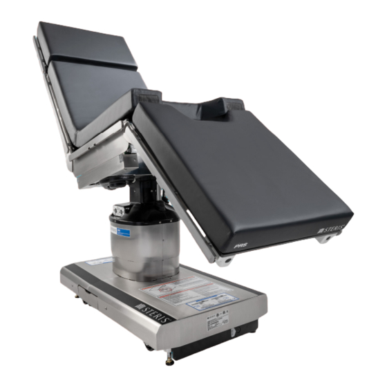
- Page 1 OPERATOR MANUAL STERIS 4095 General Surgical Table Rev. B 056404-443...
-
Page 3: Word From Steris
Do not operate or service the equipment until you have become familiar with this information. WARNING – PERSONAL INJURY HAZARD AND POSSIBLE REGULATORY VIOLATION: Any alteration of the surgical table not authorized or performed by STERIS which could affect its operation will void the warranty, could adversely affect operator safety and could violate national, state or local regulations. - Page 4 Comprehensive instructions for monthly, quarterly and semi-annual preventive maintenance can be found in the Maintenance Manual (available from STERIS). Only STERIS-trained personnel should attempt to perform maintenance on the table, to avoid personal injury, improper equipment performance, invalidation of the equipment warranty or other costly damage.
- Page 5 STERIS Ireland Limited IDA Business and Technology Park Tullamore County Offaly R35 X865 Ireland Manufactured by: STERIS Corporation 2720 Gunter Park East Montgomery, AL 36109 • USA TEL: 334 277 6660 www.steris.com Class 1 Equipment Type B Equipment Splash-Proof Equipment (enclosed equipment protected against splashing...
- Page 6 056404-443 Operator Manual Introduction...
-
Page 7: Table Of Contents
TABLE OF CONTENTS Section Number Description Page Word from STERIS..........................0-i Safety Precautions and Pinch Points ..................1-1 Introduction ............................1-1 Warnings and Cautions ......................... 1-1 Pinch Points ............................1-6 Tabletop Articulation and Weight Limitation ..................1-8 1.4.1 Positioning Patient on Table ......................1-8 1.4.2 Table Repositioning With Patient Aboard —... - Page 8 TABLE OF CONTENTS (CONT’D) Section Number Description Page 4.10.2Removing the Head Rest ......................4-8 4.11 Installing/Removing Leg Section ......................4-9 4.11.1Installing the Leg Section ......................4-9 4.11.2Removing the Leg Section ......................4-10 4.12 Installing/Removing Table Pads ......................4-11 4.13 Installing/Removing X-Ray Top ......................4-12 4.14 Accessories/Side Rails ........................
- Page 9 TABLE OF CONTENTS (CONT’D) Section Number Description Page Monthly Maintenance..........................6-7 Battery Charging ............................ 6-7 6.6.1 What You Should Know Before Charging the Batteries............... 6-7 6.6.2 Battery Charging Procedure......................6-8 Replacement Parts ..........................6-10 Auto Limit Sensor (ALS) Check ......................6-11 LEVEL Check ............................
- Page 10 056404-443 Operator Manual Table of Contents...
- Page 11 Figure 1-2.Pinch Points (Illustration 2 of 2)......................1-7 Figure 2-1.Universal Hand Control........................2-3 Figure 3-1. Table Components..........................3-2 Figure 3-2. Table Articulation..........................3-4 Figure 3-3. STERIS 4095 Tabletop Dimensions (Typical)..................3-5 Figure 3-4. Image Amplification Coverage......................3-5 Figure 3-5. Base Dimensions..........................3-6 Figure 4-1. Installing or Replacing Fuses......................4-2 Figure 4-2.
- Page 12 PS00000058 Operator Manual Table of Contents...
- Page 13 That Are Not Life-Supporting (per IEC 60601-2 Clause 6.8.3.201 b Table 204)......A-4 Table A-4 . Recommended Separation Distances Between Portable and Mobile RF Communications Equipment and STERIS 4095 General Surgical Table (per IEC 60601-2 Clause 6.8.3.201 b Table 206) ..A-5 Table of Contents Operator Manual...
- Page 14 056404-443 Operator Manual Table of Contents...
-
Page 15: Safety Precautions And Pinch Points
WARNING – PERSONAL INJURY HAZARD AND POSSIBLE REGULATORY VIOLATION: Any alteration of the surgical table not authorized or performed by STERIS which could affect its operation will void the warranty, could adversely affect operator safety and could violate national, state or local regulations. - Page 16 If the integrity of the external protective ground installation or arrangement is in doubt, operate the table from its internal power source. If an antistatic path is necessary, STERIS recommends antistatic pads (specifically developed for this table) in direct contact with the patient. Table must also be positioned on antistatic floor or connected to equalization device (equipotential connector).
- Page 17 WARNING – INSTABILITY HAZARD: Possible patient or user injury, as well as table or accessory failure, may result from using STERIS table accessories for other than their stated purpose – or from using accessories manufactured and sold by other companies on STERIS surgical tables.
- Page 18 Read and understand all instructions presented in this section before using the Universal Hand Control. Follow each step in the order presented in these instructions. If you need technical assistance or additional instructions, please contact STERIS. Dual-articulating headrest side rails support 100 ft-lbs. (135 N•m) maximum. The headrest end rail supports 50 ft-lbs.
- Page 19 Route the hand control cord clear of any pinch points where cord could be damaged. Use of incorrect hydraulic oil may severely damage the table and/or cause malfunction. Contact STERIS for proper hydraulic oil. After performing cleaning procedures, ensure pads, tabletop and X-ray tops are completely dry before reinstalling.
-
Page 20: Pinch Points
1.3 Pinch Points WARNING – PINCHING HAZARD: • Pinch points are created during tabletop articulation. Carefully review and possess a full understanding of all pinch points before operating the table. • To avoid serious injury, keep limbs, fingers and other body areas clear of all pinch points when positioning the table. -
Page 21: Figure 1-2.Pinch Points (Illustration 2 Of 2)
Pinch points: A) Between Kidney Elevator Mechanism and Seat Section ™ B) Between Leg Section and Seat Section C) Side Rail Lock D) Between Back Section and Seat Section E) Between Head Rest and Back Section F) Between Head Board and Head Rest Base Figure 1-2. -
Page 22: Tabletop Articulation And Weight Limitation
IMPORTANT:All patients must be restrained for proper safety regardless of the length or type of procedure. NOTE: STERIS recommends only using STERIS manufactured or distributed accessories with this table. Use of accessories not manufactured or approved by STERIS may not be compatible with this table and could result in injuries or equipment damage. -
Page 23: Patient Safety Straps
1.4.2 Table Repositioning With Patient Aboard — Not For Patient Transport! If the table needs to be repositioned within the operating room with the patient aboard, utilize the following procedure: 1. Ensure patient is properly secured. 2. Center and level tabletop with patient over column. 3. - Page 24 1-10 056404-443 Operating Manual Safety Precautions...
-
Page 25: Definitions Of Symbols
DEFINITIONS OF SYMBOLS 2.1 Symbols on Table The following is a key to symbols on the STERIS 4095 General Surgical Table. Table 2-1. Definition of Symbols on Surgical Table Symbol Definition Type B Equipment Protective Earth Ground Equipotentiality Electric Shock Hazard... - Page 26 Symbol Definition Safety Warning Amperage Rating of the Unit Voltage Rating of Unit Alternating Current Frequency Rating of Unit Power Rating Serial Number of the Unit IPX4 Splash-Proof Equipment ® INTELLIPOWER Dual Power System Power Panel (Battery Charge/Discharge Status) CHARGE BATTERY INTELLI POWER Powered By Battery...
-
Page 27: Hand Control Symbols
2.2 Hand Control Symbols This section identifies the iconic hand control buttons and the symbols which can present themselves on the control LCD Display. * SLIDE HEAD - Also used to indicate “YES” when prompted to change comparability table mode. †... -
Page 28: Table 2-1. Universal Hand Control, Screen Symbols
Universal Hand Control, Screen Symbols Table 2-1. Symbol Color Definition Green POWER: Table is connected to facility power Green POWER: Table is running with a fully charged battery Orange/Yellow POWER: Table is running with a half-charged battery Red/Yellow POWER: Table is running with a discharged battery Green FLOOR LOCK STATUS: Floor locks are engaged Orange... -
Page 29: Introduction To Table
INTRODUCTION TO TABLE 3.1 General Description CAUTION – POSSIBLE EQUIPMENT DAMAGE: Appropriate components of this surgical table have been tested and found in compliance with IEC 60601-1-2: Edition 4 2014-02, Medical Electrical Equipment – Part 1; General Requirements for Safety; Electromagnetic Compatibility (EMC). -
Page 30: Figure 3-1. Table Components
Figure 3-1 KEY: 1. Table Base 11. INTELLIPOWER Dual Power System Display 2. Column 12. Connection Panel 3. Tabletop 13. Hand Control 4. Head Rest (Dual-Articulating) 14. Auxiliary Control System 5. Back Section 15. Ground Equalization Terminal (Male Connection) 6. Kidney Elevator Mechanism 16. -
Page 31: Technical Specifications
100-240 Vac, One-Phase, 50/60 Hz, 4.0 Amp Each table is shipped from the factory configured to the electrical requirement specified on the factory order. If this electrical configuration needs to be changed in the field, consult STERIS for the needed procedure and required materials. -
Page 32: Figure 3-2. Table Articulation
Figure 3-2. Table Articulation 056404-443 Operator Manual Introduction to Table... -
Page 33: Figure 3-3. Steris 4095 Tabletop Dimensions (Typical)
SAE measurements are approximate based on metric dimensions. Figure 3-3. STERIS 4095 Tabletop Dimensions (Typical) Tabletop fully transitioned toward head end, normal patient orientation. Tabletop fully transitioned toward foot end, normal patient orientation. SAE measurements are approximate based on metric dimensions. -
Page 34: Emc/High-Frequency Interference
STERIS 4095 General Surgical Table. • The STERIS 4095 General Surgical Table should not be used adjacent to or stacked with other equipment. If so, table should be observed to verify normal operation. -
Page 35: Essential Performance
3.2.8 Essential Performance Essential Performance for Surgical Tables: 1) Support a patient without unwanted movement under single fault conditions. 2) Single fault conditions can include electrical, electromagnetic effects or mechanical problems. 3) In extreme cases of electromagnetic interference, operator may experience temporary loss of table function. This situation can be corrected by removing source of interference and power cycling surgical table if necessary. - Page 36 056404-443 Operator Manual Introduction to Table...
- Page 37 Introduction to Table Operator Manual 056404-443...
- Page 38 3-10 056404-443 Operator Manual Introduction to Table...
-
Page 39: Before Using The Table
4.1 Warnings and Cautions WARNING – PERSONAL INJURY HAZARD AND POSSIBLE REGULATORY VIOLATION: Any alteration of the surgical table not authorized or performed by STERIS which could affect its operation will void the warranty, could adversely affect operator safety and could violate national, state or local regulations. -
Page 40: Grounding
STERIS. 4.4 Positioning the Table WARNING – PERSONAL INJURY HAZARD: If an antistatic path is necessary, STERIS recommends the use of antistatic pads (specifically developed for this table) in direct contact with the patient. -
Page 41: Installing Main Control Fuses (F6 And F7)
4.6 Installing Main Control Fuses (F6 and F7) If not installed, install two 4 Amp main control fuses (F6 and F7) (639600038) into head-end of table base as follows: 1. Locate F6 and F7, 4 Amp, in a cartridge beside the ac input at head-end of table base. 2. -
Page 42: Connecting Table To Ac Power
Switch turns Green and plug symbol on INTELLIPOWER LED Display lights. NOTE: A green Main Power Switch indicates facility power is available to the STERIS 4095 General Surgical Table. A lighted plug symbol on the LED Display indicates the batteries are charging. Refer to 6.6,... -
Page 43: Connecting Universal Hand Control
4.8 Connecting Universal Hand Control Figure 4-4. Connecting Universal Hand Control For the following steps, refer to Figure 4-4 Figure 4-5 as needed. 1. Remove universal hand control from package. 2. Lift hinged plastic protective cover for handle connection socket. 3. -
Page 44: Connecting Optional Foot Control
6. Place hand control on table side rail. 4.9 Connecting Optional Foot Control Figure 4-6. Connecting Optional Foot Control The optional foot control allows operator to control HEIGHT, TREND and TILT movements. Install the option as follows, referring to Figure 4-6 Figure 4-7 as needed. -
Page 45: Figure 4-7. Foot Control, Connection Detail
Foot Control connects here on connection panel. Optional Foot Control Lifting plastic protective cover prior to connecting foot control. Figure 4-7. Foot Control, Connection Detail 4. Push foot control plug into table socket until a "click" is heard. 5. Place foot control where it cannot be damaged. Operating Instructions Operator Manual 056404-443... -
Page 46: Installing/Removing Dual-Articulating Head Rest
4.10 Installing/Removing Dual-Articulating Head Rest NOTE: For instructions on adjusting the head rest, refer to 5, O and to ECTION PERATING THE URGICAL ABLE Figure 5-1. WARNING – PERSONAL INJURY HAZARD: Dual-articulating headrest side rails support 100 ft-lbs. (135 N•m) maximum. The headrest end rail supports 50 ft-lbs. -
Page 47: Installing/Removing Leg Section
4.11 Installing/Removing Leg Section WARNING – PERSONAL INJURY HAZARD: Do not exceed 350 lbs. (159 kg) on the leg section. 4.11.1 Installing the Leg Section NOTE: The table is equipped with Hi-Lock™ locking mechanism enabling quick and easy removal/installation of the leg section with a safety lock feature. -
Page 48: 2Removing The Leg Section
4.11.2 Removing the Leg Section ™ The surgical table leg section is designed to be easily removed (Hi-Lock locking mechanism) to enable procedures requiring optional leg supports. The leg section can be removed while a patient is on the table. Remove the leg section as follows: WARNING –... -
Page 49: Installing/Removing Table Pads
4.12 Installing/Removing Table Pads Conductive Tabletop Pads will be of one of two varieties (related to tabletop attachment): • Pads backed with “hook-and-loop” fastener strips, which mate to hook-and-loop strips on the tabletop. • Pads with “mushroom-type” fasteners (non hook-and-loop) To install a table pad, place pad in position and firmly press associated fasteners together. -
Page 50: Installing/Removing X-Ray Top
4.13 Installing/Removing X-Ray Top The STERIS 4095 General Surgical Table is designed to enable installation of an X-ray top to allow use of X-ray cassette film. Attach the four-part X-ray top as follows (see Figure 4-13): 1. Carefully remove X-ray top sections from packing container. -
Page 51: Accessories/Side Rails
4.14 Accessories/Side Rails The standard STERIS permanently attached 3/8" wide x 1-1/8" tall (9.5 x 28.6 mm) side rails allow for the use of many standard surgery table attachments and accessories. The rails consist of one rail mounted to each side of each tabletop main section. - Page 52 4-14 056404-443 Operator Manual Operating Instructions...
-
Page 53: Surgical Table Operation
SURGICAL TABLE OPERATION 5.1 Warnings and Cautions WARNING – PERSONAL INJURY HAZARD: • The table is not to be used to transport patients. With exception of slight repositioning, as detailed in the operating instructions, never disengage floor locks when patient is on table. Failure to heed this warning can result in injury to both the patient and the operating room staff. -
Page 54: Operating The Surgical Table
WARNING – TIPPING HAZARD: • Do not place patient on the table unless floor locks are engaged. • Do not use this table for patients exceeding the maximum patient weight of: • 1100 lbs. (499 kg) Load, Normal and Reverse Patient Position; raise or lower only (no tabletop articulation or slide). -
Page 55: Figure 5-1. Adjusting The Dual-Articulating Head Rest
6. Position tabletop to LEVEL. (Refer to Section 5.3, Universal Hand Control, if needed) NOTE: When the Hand Control and Foot Control are both installed, Hand Control has priority. 7. Manually adjust the head rest, if applicable, as described in steps 7.a through 7.d. NOTE: The head rest may be positioned UP or DOWN 90°... -
Page 56: Universal Hand Control
The Universal Hand Control is to be operated only by users who have been successfully trained on operation of the applicable Surgical Table in conjunction with the Universal Hand Control. Please contact STERIS for appropriate guidance in-service and training. -
Page 57: Figure 5-2. Universal Hand Control Screen
Normal Display This normal display shows, from left to right: • Fully charged battery is powering the surgical table. • Slide is positioned six inches toward patient’s head. • Kidney bridge is up. • Floor locks are engaged . Error Display This display (error indicated by wrench symbol) shows: •... -
Page 58: Operating The Universal Hand Control
5. If Surgical Table does not match compatibility mode, the Universal Hand Control displays a screen permitting user to select the correct compatibility mode (the mode that matches table type detected during power on). Example: a 4095 Surgical Table is detected but the Universal Hand Control is configured for a different table. Press Press... -
Page 59: Table 5-1. Universal Hand Control And Surgical Table - Compatibility Mismatch
Refer to Table 5-1 for situation when Universal Hand Control and Surgical Table Compatibility Modes do not match. Table 5-1. Universal Hand Control and Surgical Table — Compatibility Mismatch Scenario* Corrective Action When table is powered on, user is prompted to select [applicable] Compat- 1. -
Page 60: Message Display With Numeric Error Codes
ALARM - Controller button If no button found depressed, press STOP to stop any table depressed too long. movement and call STERIS. If button was pressed for more than one minute, release button and repress for less than one minute. - Page 61 Combination movements (Level, Flex and Reflex) are not recalibration. allowed. Call STERIS Service. ALARM - Battery fuse Protection fuse not installed or has failed. Call STERIS Service missing or bad connection. to ensure fuse is installed or to replace fuse. ALARM - Battery voltage Call STERIS Service.
-
Page 62: Power-On Error Messages
30 minutes while unlocked or 10 hours when locked. ALARM - Control PC Board Call STERIS Service. Have Control PC Board lithium real time battery failure (not installed, clock battery replaced. bad or bad contact). ALARM - Communication Ensure primary hand control is plugged into table. -
Page 63: Optional Foot Control Operation
2) When table is turned OFF, control system stores orientation status. Before any new positioning is attempted, ensure table patient configuration is correct. 3) The head rest is manually adjusted and is not affected by Reverse Orientation button operation. 4) FLEX and REFLEX functions are NOT available for patient safety. 5) When operating in REVERSE ORIENTATION, LEVEL function does NOT operate. -
Page 64: Backup Hand Control Description
The Backup Hand Control pushbutton descriptions are as follows (Figure 5-5): NOTE: Simply release the Backup Hand Control pushbutton when desired STERIS 4095 General Surgical Table Tabletop position has been reached and table automatically stops and locks in position. Refer to 3.2.3, ECTION , for the positioning of the following table functions. -
Page 65: Return Backup Control System
LEG UP: When depressed and pumping simultaneously, the tabletop leg section raises. LEG DN: When depressed and pumping simultaneously, the tabletop leg section lowers. KIDNEY UP: When depressed and pumping simultaneously, the tabletop KIDNEY Elevator raises to the maximum 4" (110 mm). KIDNEY DN: When depressed and pumping, the tabletop Kidney Elevator Mechanism lowers. - Page 66 5-14 056404-443 Operator Manual Operating Instructions...
-
Page 67: Routine Maintenance
6.1 Read Before Performing Routine Maintenance WARNING – PERSONAL INJURY AND/OR EQUIPMENT DAMAGE HAZARD: • Repairs and adjustments to this equipment must be made only by STERIS or STERIS-trained service personnel. Maintenance performed by unqualified personnel or installation of unauthorized parts could cause personal injury, result in improper equipment performance, invalidate the warranty, or result in costly damage. -
Page 68: Guidelines For Cleaning Surgical Tables
6.2 Guidelines for Cleaning Surgical Tables 6.2.1 Introduction This section provides information pertaining to: • Disinfectants • Cleaning Materials • Prolonging Mattress and Pad Lives Prior to cleaning a table or table accessories, ensure you are familiar with these three topics, additionally, it is crucial that you understand the content presented in Section 1, Safety Precautions and Pinch Points. -
Page 69: Cleaning Materials
Approved cleaning and disinfecting solutions (prepared as directed on product labels). 6.2.4 Prolonging Mattress and Pad Lives To ensure prolonged use of STERIS mattresses and pads, abide by following: 1. Inspect mattress prior to and/or after use to check for mattress integrity. -
Page 70: Instructions For Cleaning Surgical Tables
6.3 Instructions for Cleaning Surgical Tables 6.3.1 Introduction This section provides cleaning and disinfecting instructions for the tasks presented in Table 6-1. Prior to cleaning or disinfecting a table or a table accessory. ensure you are familiar with the following: Section 1, Safety Precautions and Pinch Points Section 6.2.2, Disinfectants Section 6.2.3, Cleaning Materials... -
Page 71: Removing Gross Soils (After Each Use And Weekly)
6.3.2 Removing Gross Soils (After each use and weekly) IMPORTANT! Prior to cleaning, ensure familiarity with Section 1, Safety Precautions and Pinch Points. NOTE: Ensure protective covers are installed over receptacles. 1. Remove gross soil with a disposable cloth 2. Place used cloth in an appropriate biohazardous waste disposal container. 6.3.3 Cleaning Tabletop and Pads (After each use and weekly) IMPORTANT! Prior to cleaning, ensure familiarity with... -
Page 72: Cleaning The Hand Control (After Each Use And Weekly)
6. Repeat steps 1 through 5 for other articulation-related surfaces. 7. If table will not be used, turn hand control OFF when finished with cleaning procedure. 6.4 Bi-Weekly Maintenance Operate each STERIS 4095 General Surgical Table function (refer to 5, S ECTION... -
Page 73: Monthly Maintenance
6.5 Monthly Maintenance Check STERIS 4095 General Surgical Table casters and floor locks for any accumulated debris and clean as follows: NOTE: Ensure Hand Control is in proper working order and good condition. 1. Ensure floor locks are properly engaged. -
Page 74: Battery Charging Procedure
6.6.2 Battery Charging Procedure WARNING – PERSONAL INJURY AND/OR EQUIPMENT DAMAGE HAZARD: Repairs and adjustments to this equipment must be made only by STERIS or STERIS-trained service personnel. Maintenance performed by unqualified personnel or installation of unauthorized parts could cause personal injury, result in improper equipment performance, invalidate the warranty, or result in costly damage. -
Page 75: Figure 6-2. Led Relation To Battery Voltage
> 24.2 V < 23.6 V < 23.0 V < 24.2 V < 23.4 V < 22.8 V < 24.0 V < 23.2 V < 22.6 V < 23.8 V Figure 6-2. LED Relation to Battery Voltage Recharge batteries as follows: 1. -
Page 76: Replacement Parts
6.7 Replacement Parts The parts listed in this section are those necessary to do minor maintenance on the STERIS 4095 General Surgical Table. To order replacement parts, proceed as follows: 1. Include part number and description listed in Table 6-2. -
Page 77: Auto Limit Sensor (Als) Check
KIDNEY Elevator and lateral tilt. b. Trendelenburg and back. c. Leg. 4. Use a level and ensure tabletop is level. If not, call STERIS. 6.10 Auxiliary Control Check Check the STERIS 4095 General Surgical Table auxiliary control system as follows: 1. -
Page 78: Sealing Table Covers
6.11 Sealing Table Covers Whenever the Table Column cover assembly and/or Table Base cover are removed and then returned, the covers need sealed to prevent fluid intrusion to meet IPX4 requirements. Seal the covers as follows: NOTE: Remove all old sealant and clean all mating parts before reapplying the silicone sealant. Use RTV 123 Black Silicone Sealant (R005300-568). -
Page 79: Figure 6-5. Seal Mating Areas Between Front And Rear Base Covers
Seal Area Figure 6-5. Seal Mating Areas Between Front and Rear Base Covers 4. Apply RTV to bottom of each V-shaped cut-out around interface with column covers (see 6-6). IGURE Seal Areas Seal Areas Figure 6-6. Apply RTV to V-Shaped Cut-Outs 5. -
Page 80: 2One-Part Base Cover (Plastic)
Seal Area Figure 6-8. Seal Around Upper Plastic Covers and Column 7. Seal along both seams of upper plastic column covers as shown in 6-9. IGURE Seal Area Figure 6-9. Seal Along Both Seams of Upper Plastic Column Covers 8. Install lower (inner) column cover around column. 9. -
Page 81: Figure 6-10. Install Base Cover Insert And Attach To Base Cover
Screw Figure 6-10. Install Base Cover Insert and Attach to Base Cover 3. Apply RTV to seam between base cover insert and base cover (see 6-11). IGURE Seal Area Figure 6-11. Seal Seam Between Base Cover Insert and Base Cover 4. - Page 82 6-16 056404-443 Operator Manual Routine Maintenance...
-
Page 83: Troubleshooting
Calling For Service: First, try to define the situation and determine whether you can solve it yourself (see Table 7-1 or Table 7-2). If you cannot solve the situation, call STERIS and give the following information for the table: model number, serial number, date of purchase. - Page 84 No Power – table deactivates after 30 minutes of non- use. Press any button on hand control (except STOP). Faulty hand control** – replace. Call STERIS.* Table does not tilt right/left using hand control. Hand control not on – Press any button on hand control (except STOP).
-
Page 85: Table 7-2. Troubleshooting Chart, Lcd Message
Table 7-2. Troubleshooting Chart, LCD Message FAULT DISPLAYED FAULT DESCRIPTION FAULT ACTION 1 KEY ONLY Two pushbuttons are pressed at the same Press one button at a time or replace Hand time Control for defective button. DUAL COMMAND Commands are sent from the optional foot Hand control has priority. - Page 86 Table 7-2. Troubleshooting Chart, LCD Message (Cont’d) FAULT DISPLAYED FAULT DESCRIPTION FAULT ACTION VOLTAGE PEAK Battery voltage reaches 31 V (batteries are Immediately disconnect power cord; overcharging which can damage table). replace power supply VALVE FAIL Valve does not shut off. Check for shorted solenoid valve (67...
-
Page 87: Appendix A - Emc Compliance
EMC COMPLIANCE TECHNICAL DATA The STERIS 4095 General Surgical Table is designed for most surgical procedures with maximum radiological access without patient reversing. The STERIS 4095 General Surgical Table and related components are intended for use in the electromagnetic environment specified in... -
Page 88: Table A-1 . Guidance And Manufacturer's Declaration - Electromagnetic Emissions - For All Equipment And Systems (Per Iec 60601-2 Clause 6.8.3.201 A - 3 Table 201
Systems (per IEC 60601-2 Clause 6.8.3.201 a – 3 Table 201) The STERIS 4095 General Surgical Table and related components are intended for use in the electromagnetic environment specified below. The Customer or the user should ensure this STERIS 4095 General Surgical Table is used in such an environment. -
Page 89: Table A-2 . Guidance And Manufacturer's Declaration - Electromagnetic Immunity For All Equipment
Systems (per IEC 60601-2 Clause 6.8.3.201 a – 6 Table 202) The STERIS 4095 General Surgical Table and related components are intended for use in the electromagnetic environment specified below. The Customer or the user should ensure this STERIS 4095 General Surgical Table is used in such an environment. -
Page 90: Table A-3 . Guidance And Manufacturer's Declaration - Electromagnetic Immunity For Equipment And Systems
Systems That Are Not Life-Supporting (per IEC 60601-2 Clause 6.8.3.201 b Table 204) The STERIS 4095 General Surgical Table and related components are intended for use in the electromagnetic environment specified below. The Customer or the user should ensure this STERIS 4095 General Surgical Table is used in such an environment. -
Page 91: Table A-4 . Recommended Separation Distances Between Portable And Mobile Rf Communications Equipment
WARNING:Portable RF communications equipment (including peripherals such as antenna cables and external antennas) should be used no closer than 30 cm (12 inches) to any part of the 4095 General Surgical Table, including cables specified by the STERIS. Otherwise, degradation of the performance of this equipment could result. - Page 92 056404-443 Operator Manual Appendix A...
Need help?
Do you have a question about the 4095 and is the answer not in the manual?
Questions and answers
WHAT CAUSES THE STERIS 5085 or 5095 BED TO MOVE SLOW WHEN SLIDING IT TO THE FEET .
The Steris 5085 or 5095 bed may move slowly when sliding it toward the feet if there is a SLIDE sensor failure. This failure restricts combination movements and disables SLIDE toward head and floor unlock/lock commands.
This answer is automatically generated