
Related Manuals for Steris Hausted 4E7APRST


Summary of Contents for Steris Hausted 4E7APRST
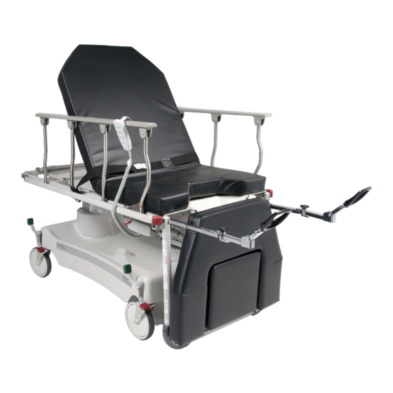
- Page 1 OPERATING MANUAL ® Hausted Converge Multi-Purpose Treatment and Exam Stretcher - Electric Powered Models: 4E7APRST and 4D7APRST (10/12/06) 075995...
- Page 2 If missing, contact STERIS for replacement copies, giving the serial number and model numbers of the unit. STERIS carries a complete line of accessories for use with this stretcher. A STERIS representative will gladly review these with you.
- Page 3 EC Authorized Representative STERIS Limited STERIS House Jays Close Viables Basingstoke Hampshire RG22 4AX UNITED KINGDOM Manufactured by: STERIS Corporation 2720 Gunter Park East Montgomery, AL 36109 • USA TEL: 334 277 6660 FAX: 334 271 5450 Class 1 Equipment...
-
Page 4: Table Of Contents
TABLE OF CONTENTS Section Title Page 1 LISTING OF WARNINGS AND CAUTIONS ........1-1 2 UNPACKING INSTRUCTIONS ............2-1 3 OPERATING INSTRUCTIONS ............3-1 3.1 Stretcher Specifications ....................3-1 3.2 Features, Warnings and Proper Operation ..............3-2 3.3 Braking and Steering Operation ................... 3-4 3.31 Applying the Brakes .................... -
Page 5: Listing Of Warnings And Cautions
LISTING OF WARNINGS AND CAUTIONS The following is a listing of the safety precautions which must be observed when operating and servicing this equipment. WARNINGS indicate the potential for danger to personnel, and CAUTIONS indicate the potential for damage to equipment. - Page 6 WARNINGS – CAUTIONS AND PROPER OPERATION: (continued) Do not use a sharp instrument to remove fuse, as it may scratch the circuit board. The batteries are wired in series, failure to install or rewire the same way may cause the batteries to explode. The stretcher has a warning label on the tube of the leg section stating: Do not transport patient in the chair configuration (tipping may occur).
-
Page 7: Unpacking Instructions
If all features work properly, go to step 5. If any of the features of the stretcher do not work properly, call STERIS for service. Step 5 – Clean the stretcher using a mild detergent to remove any dirt accumulated during shipment. -
Page 8: Operating Instructions
(500 lbs.) NOTE: All dimensions are specified in 25.5 Min inches. Height 95° Max. All dimension are ±.375 inches. STERIS reserves the right to change specifications without notice. 4.5 Min Floor 13.00 Rail Unit weight: 315 lbs. Clearnce Half Height 81.0 Overall Length... -
Page 9: Features, Warnings And Proper Operation
J. The stretcher has a warning WARNINGS – CAUTIONS 3.2 Features, AND PROPER OPERATION: label on the end of the foot Warnings and Proper section stating: Do not sit A. The stretchers have a Operation on foot section. Tipping may warning label located at the occur. - Page 10 Fowler Backrest 3 Postion Patient Side Rails See Warning F See Warnings C & G Standard 3" Thick Pad Perneal Cutout/Pan Nurse Control Box See Warning H Built In Patient Heel Stirrups Warning Label See Warning I Protective Bumpers Leg Section Warning Label See Warning R Built In Oxygen Tank Holder...
-
Page 11: Braking And Steering Operation
3.3 Braking and Steering Operation 3.31 Applying the Brakes The four wheel central braking system is activated by depressing the red pedal at any of the four corners of the unit (Figure 3-1). To fully engage the brakes, the pedal should be pressed to approximately 45º. All four caster wheels should be locked from swiveling and rotating. -
Page 12: Electric Control Locations
3.4 Electric Control Locations To access the nurses control panel, pull out on the handle located at the head 3.4.1 Nurses Control end of the unit, under the top (Figure 3-4). Panel Figure 3-4. 3.4.2 Patient Pendant The patient pendant has an adjustable location and may be located on either side rail (Figure 3-5). -
Page 13: Litter Top Adjustment
3.5 Litter Top Adjustment Lockout: Unlocking: Turn the knob located under the third set of buttons on the CAUTION: The lock-out de- control panel, clockwise approximately 90º (Figure 3-8). Locking: Turn the knob activates pendant and con- under the third set of buttons, counter-clockwise approximately 90º. trol panel. -
Page 14: Quick Drop Activation (Fowler Backrest)
3.5.3 Quick Drop The stretcher is equipped with manual override function for the Fowler backrest. Activation (Fowler This option should only be used in an emergency situation. To activate the quick Backrest) drop, support the Fowler backrest and pull out on the red “T” handle (Figure 3- 14) located under the litter top on the patient’s left side near the leg section. -
Page 15: Trendelenburg Adjustment
3.5.5 Trendelenburg Lockout: See “Lockout” in the Section 3.5.1 Height Adjustment Instructions . Adjustment Nurse: Trendelenburg: Press the top button on the fourth set of buttons on the control panel (Figure 3-20). Hold in the button until desired angle is achieved. Rev-Trendelenberg: Press the bottom button on the fourth set of buttons on the control panel (Figure 3-21). -
Page 16: Heel Stirrup Operation
3.7 Heel Stirrup Operation Lower the foot section (Figure 3-24) to approximately 20º below horizontal. Pull 3.7.1 Extending the Heel the heel stirrup out from under the top (Figure 3-25). Grasp the heel stirrup and Stirrup fold out (Figure 3-26). At this point, place the patient’s feet into the heel stirrup. W A R N I N G –... -
Page 17: Push Handle Operation (Optional Accessory)
3.8 Push Handle Operation (optional accessory) 3.8.1 Raising the Push Rotate the push handle up (Figure 3-31) until it stops, slide the push handle Handles down into the socket until it stops. Repeat process for handle on the other side (Figure 3-32). -
Page 18: Perminent Mounted I.v. Rod Operation
3.9 Perminent Mounted I.V. Rod Operation W A R N I N G – P E R S O N A L INJURY: Be sure I.V. rod is inserted completely into socket up to the arrow before applying any load. 3.9.1 Putting I.V. -
Page 19: Trouble Shooting Guide
TROUBLE SHOOTING GUIDE 4.1 Electric Powered Stretchers WARNING: To reduce the risk of electric shock, do not remove the cover. Unit is to be serviced by qualified per- sonnel only. Then One motor or one column does not Step1: Check all motor and column plug connections at the controller box. move but all others are operating Step 2: If a column does not move: Check the the connection at the column. -
Page 20: Battery Replacement Instructions
Step 3: Replace (both) batteries with ‘YUSHA’ #NP 1.2-12, 12 volt, 1.2 Ah batteries. (Steris P/N 075759 – 2 required. Step 4: Be sure battery connector in in place on left side of batteries. Step 5: Replace cover. 075995... -
Page 21: Recommended Preventive Maintenance
Wipe with damp cloth to remove After each use Routine hospital grade • Lubricate pivot points after cleaning Accessories any foreign materials disinfectants, soap and water For more details information, please contact: STERIS Corporation at: 1-800-333-8828 Recommended Preventive Maintenance Operator Manual 075995... -
Page 22: Optional Accessories
Self-Storing Push Bars 075170-00 Procto Board SA0941-00 Articulating Headrest It is recommended that only STERIS approved accessories be used with this device. To order accessories or for more detailed information on accessories please contact STERIS Corporation at: 1-800-333-8828 Optional Accessories Operator Manual... -
Page 23: Recommended Replacement Parts
RECOMMENDED REPLACEMENT PARTS Recommended Replacement Parts Operator Manual 075995... - Page 24 Important Note: To reduce the risk of electric shock, do not remove the cover. Unit is to be serviced by qualified personnel only. For detailed plug locations, see Figures 7-9 & 7-10. For detailed label locations, see Figure 7-11. Figure 7-1. 4E7/4D7 Base Assembly 075995 Operator Manual Recommended Replacement Parts...
- Page 25 FIG. & UNITS PER PART ITEM DESCRIPTION ASSEMBLY NUMBER 7-1- 075907 4E7/4D7 BASE ASSEMBLY ............075910 ASSEMBLY, Base Frame ............062672 CASTER, Tente, Brake ..............062671 CASTER, Tente, Swivel Lock ............062659 PLATE, Caster Bolt Lock ............. 062685 SCREW, Hex Head Cap, M8 x 1.25 x 12.00" Long ..... 065041 BOLT, Eye, 5/16-18 ..............
- Page 26 34 35 14 17 19 36 Important Note: To reduce the risk of electric shock, do not remove the cover. Unit is to be serviced by qualified personnel only. For detailed plug locations, see Figures 7-9 & 7-10. For detailed label locations, see Figure 7-11. Figure 7-2.
- Page 27 FIG. & UNITS PER PART ITEM DESCRIPTION ASSEMBLY NUMBER 7-2- TOP ASSEMBLY ................. P75923 WELDMENT, Top Assembly ............P75909 ASSEMBLY, Sub-, Foot Section ..........031036 SCREW, Oval Head Pivot ............075235 EXTRUSION, Tube Protector ............031314 PIN, Spring, 3/16" x 3/4" .............. 065796 KNOB, Tee, 5/16-18 ..............
- Page 28 Heel stirrup assembly – left shown (Item 16) , Items 21 through 36 are part of items 16 & 17 Important Note: To reduce the risk of electric shock, do not remove the cover. Unit is to be serviced by quali- fied personnel only.
- Page 29 FIG. & UNITS PER PART ITEM DESCRIPTION ASSEMBLY NUMBER 7-3- TOP ASSEMBLY (CONTINUED) ..........P75743 HANGER, Coil Cord ..............031000 SCREW, Hex Head Machine, #10-24 x 1.2" Long ...... 031421 NUT, Lock, #10 24 ............... 075717 PENDANT, CB-14 ................ 075716 CONTROL, Nurse ................
- Page 30 For detailed label locations, see Figure 7-11. Figure 7-4. Rail Assembly 075995 Operator Manual Recommended Replacement Parts...
- Page 31 FIG. & UNITS PER PART ITEM DESCRIPTION ASSEMBLY NUMBER 7-4- 075979 RAIL ASSEMBLY, RIGHT ............075978 RAIL ASSEMBLY, LEFT ............. 075982 ASSEMBLY, Top Cap, Left ............075980 ASSEMBLY, Top Cap, Right ............068882 TUBE, Offset Leg ................. 068883 TUBE, Lock Leg ................068886 RIVET, Chery Mate (2 Pc) ............
- Page 32 Important Note: To reduce the risk of electric shock, do not remove the cover. Unit is to be serviced by qualified personnel only. For detailed plug locations, see Figures 7-9 & 7-10. For detailed label locations, see Figure 7-11. Figure 7-5. Fowler Assembly 7-10 075995 Operator Manual...
- Page 33 FIG. & UNITS PER PART ITEM DESCRIPTION ASSEMBLY NUMBER 7-5- FOWLER ASSEMBLY ..............P75964 WELDMENT, Fowler Backrest ............. P66546 SHEET, Fowler Cover ..............000794 RIVET, Pop, 3/16" x 1/2" .............. 066696 PIN, Fowler Hinge ................ 075503 SCREW, Phillips Pan Head, #10-24 x 1-3/8" Long ..... 031421 NUT, Lock, #10-24 ...............
- Page 34 Opening of tube protector is to be in back of foot section - 2 places Important Note: To reduce the risk of electric shock, do not remove the cover. Unit is to be serviced by qualified personnel only. For detailed plug locations, see Figures 7-9 & 7-10. For detailed label locations, see Figure 7-11.
- Page 35 FIG. & UNITS PER PART ITEM DESCRIPTION ASSEMBLY NUMBER 7-6- P75900 FOOT SECTION ASSEMBLY ............. P75912 WELDMENT, Foot Section ............P75932 SHEET, Foot Section ..............P75964 WELDMENT, Foot Board ............. P75967 ASSEMBLY, Foot Board Link, Left ..........P75968 ASSEMBLY, Foot Board Link, Right ..........065974 MAT, Foot Board ................
- Page 36 Important Note: To reduce the risk of electric shock, do not remove the cover. Unit is to be serviced by qualified personnel only. For detailed plug locations, see Fig- ures 7-9 & 7-10. For detailed label locations, see Fig- ure 7-11. Figure 7-7.
- Page 37 FIG. & UNITS PER PART ITEM DESCRIPTION ASSEMBLY NUMBER 7-7- 076136 4E7 CONTROLLER ASSEMBLY (AFTER 5/1/00) ..... 076184 4D7 CONTROLLER ASSEMBLY (AFTER 5/1/00) ..... 066237 SPACER ..................075749 ASSEMBLY, Low Battery L.E.D........... 068979 BASE, Junction Box ..............076125 WIRE, Ground ................031184 RIVET, Pop, 3/6"...
- Page 38 Important Note: To re- duce the risk of electric shock, do not remove the cover. Unit is to be serviced by quali- fied personnel only. For detailed plug locations, see Figures 7-9 & 7-10. For detailed label locations, see Figure 7-11. Figure 7-8.
- Page 39 FIG. & UNITS PER PART ITEM DESCRIPTION ASSEMBLY NUMBER 7-8- 075901 4E7 CONTROLLER ASSEMBLY (BEFORE 5/1/00) ....066237 SPACER ..................075749 ASSEMBLY, Low Battery L.E.D........... 068979 BASE, Junction Box ..............068980 COVER, Junction Box ..............031184 RIVET, Pop, 3/16" ................ 075044 CONTROLLER, CB-14 ..............
- Page 40 See Note #2 Important Note: To re- duce the risk of electric shock, do not remove the cover. Unit is to be serviced by quali- fied personnel only. For detailed label locations, see Figure 7-11. See Note #3 NOTE: (unless otherwise specified) 1.
- Page 41 FIG. & UNITS PER PART ITEM DESCRIPTION ASSEMBLY NUMBER 7-9- CONTROLLER ASSEMBLY (AFTER 5/1/00) ......063031 BUTTON, Wire Tie ............... 065403 TIE, Cable ..................068864 RELIEF, Strain ................031000 SCREW, Washer Head Machine, #10-24 x 1/2" Long ....031421 NUT, Lock, #10-24 ............... 061159 SCREW, Truss Head Machine, #10-24 x 5/8"...
- Page 42 Important Note: To reduce the risk of electric shock, do not remove the cover. Unit is to be serviced by qualified personnel only. See Note #2 For detailed label locations, see Figure 7-11. NOTE: (unless otherwise specified) 1. Wrap excess cable and secure with cable tie (Item 2).
- Page 43 FIG. & UNITS PER PART ITEM DESCRIPTION ASSEMBLY NUMBER 7-10- CONTROLLER ASSEMBLY (BEFORE 5/1/00) ......063031 BUTTON, Wire Tie ............... 065403 TIE, Cable ..................068864 RELIEF, Strain ................031000 SCREW, Washer Head Machine, #10-24 x 1/2" Long ....031421 NUT, Lock, #10-24 ............... 061159 SCREW, Truss Head Machine, #10-24 x 5/8"...
- Page 44 Figure 7-11. Label and Pad Locations 7-22 075995 Operator Manual Recommended Replacement Parts...
- Page 45 FIG. & UNITS PER PART ITEM DESCRIPTION ASSEMBLY NUMBER 7-11- 4E7 LABEL AND PAD LOCATIONS .......... 4D7 LABEL AND PAD LOCATIONS .......... 075035 LABEL, Control Panel ..............075490 LABEL, Max Patient Weight ............075040 LABEL, Emergency Drop Back Rest ........... 075986 LABEL, Stirrup Warning ...............
- Page 46 Figure 7-12. Push Bar Assembly, Tubular Style Tops 7-24 075995 Operator Manual Recommended Replacement Parts...
- Page 47 FIG. & UNITS PER PART ITEM DESCRIPTION ASSEMBLY NUMBER 7-12- 075665 PUSH BAR ASSEMBLY, TUBULAR STYLE TOPS, AIRGLIDE ................. 075631 ASSEMBLY, Push Handle A ............075642 ASSEMBLY, Push Handle B ............075637 • WELDMENT, Push Handle ............075633 • BRACKET, Hinge, A ..............031076 •...
- Page 48 NOTE: I.V. rod is shown mounted on patient’s left which is standard. The I.V. rod can be mounted on the patient’s right by bolting to the other side angle using Item 13 in place of Item 8 and Item 14 in plate of Item 9. Figure 7-13.
- Page 49 FIG. & UNITS PER PART ITEM DESCRIPTION ASSEMBLY NUMBER 7-13- 075590 I.V. ROD ASSEMBLY, LEFT ............075591 I.V. ROD ASSEMBLY, RIGHT ............. 062038 SCREW, Button Head Cap, 1/4-20 x 5/8" Long ......031055 NUT, Lock, 1/4-20 ................ 075568 BRACKET, I.V. Rod Support ............075545 ASSEMBLY, Trigger Style I.V.
- Page 50 Figure 7-14. Fifth Wheel Assembly 7-28 075995 Operator Manual Recommended Replacement Parts...
- Page 51 FIG. & UNITS PER PART ITEM DESCRIPTION ASSEMBLY NUMBER 7-14- 068516 FIFTH WHEEL ASSEMBLY ............ASSEMBLY, 4E2 Base ..............051308 NYLINER, Flange, 3/4" x 1-1/8" ........... 068360 ASSEMBLY, Swivel Bracket ............068429 PLATE, 5th Wheel Hinge ............. 068415 WHEEL, 4" ................... 068543 SCREW, Hex Head Cap, 5/16-18 x 2"...
Need help?
Do you have a question about the Hausted 4E7APRST and is the answer not in the manual?
Questions and answers