
Related Manuals for Steris Amsco 3085 SP


Summary of Contents for Steris Amsco 3085 SP
- Page 1 MAINTENANCE MANUAL Amsco 3085 SP Surgical Table ® After S/N B420702-025 (10/07/10) P764332-897...
- Page 2 TABLE OF CONTENTS Section Title Part Number Operator Manual ......................P150830-353 Maintenance Instructions ................... P764332-898 Illustrated Parts Breakdown ..................P764332-899 Reference Drawings Foot Control Cord Replacement Instructions ..............755716-207 Bieri Hydraulic System Schematic ................141210-126 Bieri Hydraulic System Schematic (With S13) ..............134469-303 3085 System, Low Leak, SMT Schematic ..............141245-009 3085 System, Hermes, Low Leak, SMT Schematic ............146245-010 Power Control Schematic (Low Leak) ................141210-456...
- Page 3 OPERATOR MANUAL Amsco ® 3085 SP Surgical Table (08/10/11) P150830-353...
- Page 4 STERIS for a replacement copy, giving the serial and model numbers of the unit. STERIS carries a complete line of accessories for use with this table. A STERIS representative will gladly review these with you. A listing of the Safety Precautions to be observed when operating and...
- Page 5 EC Authorized Representative STERIS Limited Chancery House 190 Waterside Road Hamilton Industrial Park Leicester LE5 1QZ UNITED KINGDOM Manufactured by: STERIS Corporation 2720 Gunter Park East Montgomery, AL 36109 • USA Class 1 Equipment Type B Equipment Classified as IPX4...
-
Page 6: Table Of Contents
4.6 Pads and Accessories ....................4-11 4.6.1 Tabletop Pads ..................... 4-11 4.6.2 X-Ray Top Accessories ..................4-11 4.6.3 General Accessories Applied to Side Rails ............4-12 4.6.4 Accessories Specific to Amsco 3085 SP Tables..........4-13 Table of Contents Operator Manual 150830-353... - Page 7 TABLE OF CONTENTS (Cont'd) Section Title Page 5 AUXILIARY OVERRIDE SYSTEMS ..........5-1 5.1 Articulation With Electric Pump Power Available ............5-2 5.2 Articulation With No Electric Pump Power Available ............ 5-3 5.3 Floor Lock Override Systems ..................5-3 6 ROUTINE MAINTENANCE ............... 6-1 6.1 Preventive Maintenance Schedule ................
-
Page 8: Safety Precautions
Foot Extension Accessory or combination of Foot Extension and Headrest Accessories from previous design STERIS tables must not be used for reverse orientation on the 3085 SP Table. Do not use two or more Uro-Endo/Image Amplification Extension accessories together on the 3085 SP Table. - Page 9 Stabilize table when transferring patient. Possible patient or user injury, as well as table or accessory failure, may result from using STERIS table accessories for other than their stated purpose - or from using, on STERIS tables, accessories manufactured and sold by other companies.
- Page 10 ACT Enabled™ interface cord and/or optional foot control cord, if applicable) clear of any pinch points where the cord(s) could be damaged. The use of incorrect hydraulic oil may severely damage the table and/or cause malfunction. Contact STERIS for the proper oil to use.
- Page 11 Following is a key to symbols which may be on your table or controls. Definition of Symbols Symbol Definition Protective Earth (Ground) Attention, Consult Manual for Further Instructions Amperage Rating of the Unit Voltage Rating of the Unit Alternating Current Power Rating of the Unit Frequency of the Unit Equipotentiality...
- Page 12 Symbol Definition Floor Lock (Function Touch Pad) Floor Lock: Lock Floor Lock: Unlock Patient Orientation (Function Touch Pad) Normal Orientation Reverse Orientation Trendelenburg Reverse Trendelenburg Height Up (Raise) Height Down (Lower) Tilt Left Tilt Right Back Up Back Down Leg Up Leg Down Continued ...
- Page 13 Symbol Definition Flex Reflex Level IPX4 Enclosure Code Rating per IEC529 150830-353 Operator Manual Safety Precautions...
-
Page 14: Important User Information
IMPORTANT USER INFORMATION During extreme tabletop articulation, various possible pinch points exist. These 2.1 Pinch Point points are identified in Figure 2-1. All personnel involved in tabletop positioning should examine and be aware of these points before operating the table. Warnings WARNING –... - Page 15 Typical Pinch Point and Tipping Hazard When Lowering TREND HEIGHT SIDE TILT BACK Between Column Skirt and Column Cap Between Ratchet Handle and Table Frame Between Kidney Bridge and Tabletop or Between Kidney Bridge and X-ray Set TREND HEIGHT SIDE TILT BACK Column...
-
Page 16: Prevent Possible Tipping
Do not extend (lengthen) the patient support surface beyond that shown, unless • Do not use this table for pa- using a STERIS table accessory intended for this purpose and the accessory tients exceeding the 1,000-lb weight limitation is not exceeded. -
Page 17: Other Considerations
Do not exceed the ac- cessory load rating if it is lower than the table rating. Amsco 3085 SP Surgical Tables are remote control, Image Amplification 2.3 General compatible units with auxiliary override (backup) systems for the control and hydraulic systems. -
Page 18: Technical Specifications
* Each table is shipped from the factory configured to the electrical requirement specified on the factory order. If required to be changed in the field, consult STERIS for the procedure/materials required. Tables intended to be shipped to other than USA or Canada will have procedure/materials included in shipping container. -
Page 19: Installation Instructions
INSTALLATION INSTRUCTIONS NOTE: Patient grounding post/potential equalization terminal (male connector, WARNING – PERSONAL DIN 42801) is provided. Mating female connector is not furnished by STERIS. INJURY HAZARD: If the integ- IMPORTANT: Before connecting the table to your ac power system, check... -
Page 20: Install And Route Power Cord
1. Place table at desired location. 3.1 Install and Route NOTE: Omit Steps 2 and 3 if table is battery-powered. Power Cord 2. Connect female end of 20' (6 m) long power cord* to male connector located on narrow end of table base (can only be connected one way). See Figure 3-1. Lift hinged cover to access the connector. -
Page 21: Install Hand Control And Lock Table In Place
Connect the hand control plug to the proper table receptacle. 3.2 Install Hand NOTE: A spring-loaded lock ring locks plug into receptacle. When disconnecting Control and Lock the hand control, pull back on the lock ring before pulling the plug from the Table in Place receptacle. -
Page 22: Lock Table In Place
3.2.3 Lock Table in Place 1. Press ON button at top of hand control to turn table on. All LEDs on hand control may light momentarily for control system self-test when power is turned on. Refer to Figure 3-4 for identification of hand control functions. See S ECTION , to identify any problems with the hand control. -
Page 23: Hand Control Interchangeability
2. Press FLOOR LOCK Function button in center row of control buttons, and within five seconds press LOCK button (to the left of FLOOR LOCK button, see Figure 3-4). Table is locked in position as floor locks are lowered and casters are raised. -
Page 24: Operating Instructions
OPERATING INSTRUCTIONS For maximum patient positioning flexibility, the Amsco ® 3085 SP Surgical Table 4.1 Attach Headrest is designed so the headrest can be attached to either end of the table. and Orient Patient IMPORTANT: Control must be oriented as to the patient's position on table before any positioning functions are operable. - Page 25 3. Press ORIENT PATIENT Function button in center row of buttons on hand WARNING – TIPPING control and within five seconds (while LED is still lit), press appropriate HAZARD: Actuate button (NORMAL or REVERSE) to indicate orientation of patient's • Do not use this table for pa- head on table (see Figures 4-2 and 4-3).
-
Page 26: Tabletop Positioning
The tabletop may be articulated within the limits shown by use of the hand 4.2 Tabletop control positioning buttons or the optional foot control positioning pedals, or by the optional ORCS System. If these controls fail to function, refer to S Positioning ECTION , to see if the problem can be quickly determined and corrected. - Page 27 Adjust the tabletop position by using the hand control positioning buttons, as follows (see Figure 4-3): 1. Press FLOOR LOCK Function button in center row of buttons on hand control and within five seconds (while LED is still ON), press desired Actuate button (LOCK or UNLOCK) adjacent to it.
-
Page 28: Optional Foot Control Operation
2) When a normal patient load exceeds 700 lb (318 kg), moving the table from an extreme Right Tilt may require the tabletops be level. When normal patient load exceeds 900 lb (408 kg), moving the table from an extreme Right Tilt may be slow or not operate. - Page 29 2. Connect foot control assembly to table by aligning foot control cord gray plug WARNING – TIPPING red dot with table gray receptacle red dot, and pushing plug into connected HAZARD: During an articula- position (see Figure 4-5). tion if the tabletop sections NOTE: For foot control, note the following: contact an obstruction, the table may tip.
-
Page 30: Care Of Controls When Not In Use
• Lower Height – 27" (686 mm) minimum. Depress right side of HEIGHT pedal (located in the center position of foot control pedals) and release pedal when desired position has been reached to automatically stop tabletop and lock it in position. •... -
Page 31: Optional Operating Room Control System (Orcs) Operation
For voice-activation of Amsco 3085 SP Surgical Table functions, either the 4.3 Optional HERMES ® -Ready or ACT Enabled™ Interface System and appropriate hand control are needed. Operating Room Control System NOTE: Battery-powered tables should be switched OFF after each procedure to prevent unnecessary battery discharge. -
Page 32: Act Enabled System Operation
4.3.2 ACT Enabled An ORCS (not provided by STERIS) and an ACT Enabled Hand Control are System Operation required for voice- and/or touch panel-activation of the ACT Enabled Amsco 3085 SP table functions. NOTE: Battery-powered tables should be switched OFF after each procedure to prevent unnecessary battery discharge. -
Page 33: Headrest Positioning
WARNING – INSTABILITY HAZARD: Possible patient or user injury, as well as table or accessory failure, may result from using STERIS table ac- cessories for other than their Kidney Bridge stated purpose - or from us- ing, on STERIS tables, ac-... -
Page 34: Pads And Accessories
(see Figure 4-11). Accessories Removable accessories are positioned and secured by clamps or sockets which are applied to (and slide along) the side rails. Contact STERIS to order additional table accessories. WARNING – INSTABILITY HAZARD: Possible patient or... -
Page 35: General Accessories Applied To Side Rails
Perform the following for each X-ray top section: Spring Clip Projecting Short Standoff Beyond Standoff 1. Loosen screws securing spring-loaded spacers to X-ray top section. Position section on table. 2. Rotate spacers so spring clips are in line when viewed from beneath tabletop (see Figure 4-13). -
Page 36: Accessories Specific To Amsco 3085 Sp Tables
• Perineal Cutout Filler – attaches to tabletop to cover cutout and provide bariatric patients. additional patient support. (Limited to 400-lb [181 kg] patient load.) For application of other STERIS table accessories to your Amsco 3085 SP table, contact STERIS. 4-13... - Page 37 (Shown Without X-Ray Top and 2" [51 mm] Pad) Drain Tray TREND HEIGHT SIDE TILT BACK 3080/3085 Orthopedic Extension Neuro Seat Plate Figure 4-15. Accessories* for Amsco 3085 Tables *Contact STERIS for ordering information. Refer to specific accessory descriptions for weight limitations. 4-14 150830-353 Operator Manual Operating Instructions...
-
Page 38: Auxiliary Override Systems
AUXILIARY OVERRIDE SYSTEMS The Amsco ® 3085 SP Surgical Table is equipped with Auxiliary Override WARNING – EXPLOSION Systems that can be actuated at any time and that will allow table operation in HAZARD: Table must not be the event of primary control malfunction. used in the presence of flam- Articulate table according to the procedures in S 5.1, A... -
Page 39: Articulation With Electric Pump Power Available
A row of toggle switches (located on the top of column under the small hood, 5.1 Articulation With on the opposite side from the hand control connection; see Figure 5-1) is used for table movements if control power is still available. Electric Pump Power Available Articulate table as follows:... -
Page 40: Articulation With No Electric Pump Power Available
The toggle switches are used in conjunction with the foot pedal for table 5.2 Articulation With movements when no electric pump power is available. No Electric Pump Articulate table as follows: Power Available 1. Flip foot pedal down (see Figure 5-2). 2. -
Page 41: Routine Maintenance
CAUTION – POSSIBLE EQUIPMENT DAMAGE: The use of incorrect hydraulic oil may severely damage the table and/or cause malfunc- tion. Contact STERIS for the proper oil to use. ® Table 6-1. Preventive Maintenance Schedule for Amsco 3085 SP Surgical Table... - Page 42 Table 6-1. Preventive Maintenance Schedule for Amsco 3085 SP Surgical Table (Cont'd) SERVICE REQUIRED MINIMUM FREQUENCY CONTROLS Verify proper operation of all articulations for full motion. • Using hand control. 6x per year • Using override function. 6x per year •...
-
Page 43: Cleaning/Disinfecting Procedures
1. Remove gross soil with a disposable cloth and place used cloth in an 6.2 Cleaning/ appropriate biohazardous waste disposal container. Disinfecting 2. Clean tabletop as follows: Procedures a. Articulate tabletop to level position and place at a comfortable working height. -
Page 44: End-Of-Day
3. Raise table to maximum elevation to access lower surfaces. CAUTION – POSSIBLE 4. Clean bellows, shrouds, and entire base surface as follows: EQUIPMENT DAMAGE: a. Care should be taken so bellows is not torn, punctured, or ripped, and that •... -
Page 45: Biweekly Maintenance
2. Operate each table function. Operation should be smooth and quiet. WARNING – PERSONAL INJURY AND/OR EQUIPMENT If it is not, call STERIS. A factory-trained service technician will promptly DAMAGE HAZARD: Repairs arrange to have the table placed in proper working order. -
Page 46: Battery Charging Procedure
• It is not necessary to have hand control ON to charge batteries. age. Contact STERIS regard- ing service options. • On either electric-powered or battery-powered 3085 SP, power cord may be left plugged into appropriate receptacle indefinitely. It will not harm table nor WARNING –... - Page 47 2. Allow a minimum of 48 hours for full battery charge. See chart below: Charging Time Portion Charge 24 hours 90 percent 36 hours 95 percent 48 hours 100 percent 3. Verify low battery indicator LED is off and disconnect ac power. 4.
-
Page 48: Troubleshooting
Troubleshooting Chart or the Hand Control Diagnostics Chart, or if a problem tine maintenance. Contact occurs not described on the charts, please contact STERIS. A trained service STERIS to schedule preven- technician will promptly place your equipment in proper working order. - Page 49 Hand Control Diagnostics Chart NOTE: When power supplies are operational and the table is plugged into an ac receptacle, the ON touch pad green LED and ac power green LED will be ON. INDICATION CONDITION CORRECTIVE ACTION 1. Control ON – green AC AC power connected;...
- Page 50 Hand Control Diagnostics Chart (Cont'd) INDICATION CONDITION CORRECTIVE ACTION 6. All LEDs are OFF (not lit). 1. Hand control unplugged Reconnect hand control per S ECTION while table control ON; control automatically shuts off after two minutes. 2. AC power off (electric- Reconnect ac power cord per S ECTION powered table only);...
-
Page 51: Service Procedures
Contact STERIS regard- ing service options. Four circuit breakers (CB-1, CB-2, CB-3, and CB-4) protect various table 8.1 Reset Circuit components* and may be reset if tripped by a fault condition. When tripped, the circuit breaker will pop out and is readily detectable. -
Page 52: Change Fuses
Two replaceable fuses (F1 and F2) are located in a cartridge above the ac input in the table base. If one or both of the fuses are blown by a fault condition, 8.2 Change Fuses replace as follows: 1. Disconnect ac power cord from wall receptacle and table base input (see Figure 8-2). -
Page 53: Replacement Parts
2. Include model and serial numbers of your equipment on your order. 3. Send your order directly to STERIS. Contact STERIS if you need any parts not listed in Table 8-1. NOTE: Use only STERIS authorized parts on the equipment. Use of unautho- rized parts will void the warranty. - Page 54 3. USA fuses are AGC or ABC or MTH, and are also for use in Canada. F1 and F2 are slo-blow. 4. IEC fuses are IEC glass fuses. IEC fuses for F3 require IEC fuseholder, STERIS part number P129360-654. 150830-353...
-
Page 55: Disposal Hazards
Return-to-Level switch assemblies (P136807-726, P136807-727, and and/or cause malfunction. P136807-728). Quantity = 3 assemblies per table (two mercury switches per Contact STERIS for proper assembly). Two assemblies are located in the back section frame and one hydraulic oil. assembly is located in the seat section frame. Approximate total mercury per table = 18 g. - Page 57 EFINITIONS list of terminology used in this document. Thank you for choosing this fine STERIS product. INDICATIONS FOR USE STERIS is committed to ensuring your continued The Amsco 3085 SP Surgical Table is a mobile, satisfaction. This manual contains important...
- Page 58 EC Authorized Representative STERIS Ltd Chancery House 190 Waterside Road Hamilton Industrial Park Leicester LE5 1QZ UNITED KINGDOM Manufactured by: STERIS Corporation 2720 Gunter Park East Montgomery, AL 36109 • USA Class 1 Equipment Type B Equipment Classified as IPX4...
- Page 59 TABLE OF CONTENTS Section Number Description Page Safety Precautions ........................1-1 Terms, Definitions, Symbols and Special Tools................. 2-1 Terms and Definitions ..........................2-1 Symbols ..............................2-1 Special Tools/Materials Required for Maintenance ................2-1 Principles of Operation ......................... 3-1 General ..............................3-1 Table Overview .............................
- Page 60 TABLE OF CONTENTS (CONT’D) Section Number Description Page Field Test Procedure ........................6-1 General ..............................6-1 Test Instrumentation Needed ........................ 6-1 Hydraulic Pump Relief Valve ......................... 6-1 Table Observation ..........................6-2 Table Mobility............................6-2 Floor Lock Assembly ..........................6-2 Table Articulation ........................... 6-2 Tabletop Raise/Lower ..........................
- Page 61 TABLE OF CONTENTS (CONT’D) Section Number Description Page 7.12 Floor Lock Adjustment ...........................7-8 7.13 Seat Section Limit Switch Adjustment....................7-8 7.14 LS4 - Back Section Limit Switch Adjustment ..................7-9 7.15 LS5 - Column Limit Switch Adjustment ....................7-9 7.16 Lash Adjustments..........................7-10 7.16.1 Longitudinal Lash Adjustment....................7-10 7.16.2 Lateral Lash Adjustment ......................7-10 7.16.3 Rotational Lash Adjustment.....................7-10 7.17 Hydraulic Cylinder Replacement......................7-11...
- Page 62 TABLE OF CONTENTS (CONT’D) Section Number Description Page 7.29 Field Resetting of Voltage Settings...................... 7-21 7.29.1 Switches..........................7-21 7.29.2 Jumper Plug..........................7-21 7.30 Disposal Hazards..........................7-21 7.31 Column Bearing Replacement ......................7-22 7.31.1 Required Tools and Supplies ....................7-22 7.31.2 Procedure ..........................7-22 764332-898...
- Page 63 LIST OF FIGURES Description Page Figure 3-1. Amsco 3085 SP Surgical Table Components (Typical) ............. 3-3 Figure 3-2. Side Tilt............................3-4 Figure 3-3. Column Raise/Lower ......................... 3-4 Figure 3-4. Leg Up and Down........................3-5 Figure 3-5. Flex/Reflex, Trendelenburg/Reverse Trendelenburg and Back Up/Down......... 3-6 Figure 3-6.
- Page 64 Definition of Symbols on Surgical Table..................2-3 Table 2-2. Definition of Symbols on Hand Control ................... 2-4 Table 2-3 Special Tools for Amsco 3085 SP Surgical Table Maintenance ............. 2-6 Table 4-1 Preventive Maintenance Schedule for Amsco 3085 SP Surgical Table.......... 4-2 Table 4-2 Amsco 3085 SP Replacement Parts ....................
-
Page 65: Safety Precautions
If an antistatic path is necessary, STERIS recommends antistatic pads (specifically developed for this table) in direct contact with the patient. STERIS recommends that the table be positioned on antistatic floor or connected to equalization device (equipotential connector). - Page 66 WARNING – PERSONAL INJURY AND/OR EQUIPMENT DAMAGE HAZARD: Repairs and adjustments to this equipment must be made only by STERIS or STERIS-trained service personnel. Maintenance performed by unqualified personnel or installation of unauthorized parts could cause personal injury, result in improper equipment performance, invalidate the warranty or result in costly damage.
- Page 67 Do NOT pressure clean the Amsco 3085 SP Surgical Table. Route the hand control cord clear of any pinch points where cord could be damaged. Use of incorrect hydraulic oil may severely damage the table and/or cause malfunction. Contact STERIS for proper hydraulic oil.
- Page 68 CAUTION – POSSIBLE EQUIPMENT DAMAGE (CONT’D): Isolate the coil and/or pump motor from the power control by disconnecting the wires on the motor terminal board, or slip the wires off the solenoid coil that is being serviced. Always connect power cord to a properly grounded socket. To prevent rubber bumpers from being cut off, replace base shroud parts carefully and evenly.
-
Page 69: Terms, Definitions, Symbols And Special Tools
2.2 SYMBOLS functions and articulations. Table 2-1 and Table 2-2 contain symbols which may HMI - Human Machine Interface (such as Hand, appear on your Amsco 3085 SP Surgical Table and/or Auxiliary Control or Override Panel). Hand Control. I/O - Input/Output. -
Page 70: Table 2-1. Definition Of Symbols On Surgical Table
Table 2-1. Definition of Symbols on Surgical Table Symbol Definition Type B Equipment Protective Earth Ground Equipotentiality Attention, Consult Manual for Further Instructions Electric Shock Hazard WEEE Directive - Product Must Be Recycled Power Rating of Unit Serial Number of Unit Voltage Rating of Unit, Alternating Current Amperage Rating of Unit Frequency Rating of Unit... -
Page 71: Table 2-2. Definition Of Symbols On Hand Control
Table 2-2. Definition of Symbols on Hand Control Symbol Definition Floor Lock: Lock Floor Lock (Function Touch Pad) Floor Lock: Unlock Normal Orientation Patient Orientation (Function Touch Pad) Reverse Orientation Trendelenburg Reverse Trendelenburg Height Up (Raise) Height Down (Lower) Left Tilt 764332-898... - Page 72 Table 2-2. Definition of Symbols on Hand Control (Cont’d) Symbol Definition Right Tilt Back Up Back Down Leg Up Leg Down Flex Reflex Powered by AC Powered by Battery Battery Charged Level Battery Down Optional HERMES-Ready System Installed 764332-898...
-
Page 73: Table 2-3 Special Tools For Amsco 3085 Sp Surgical Table Maintenance
Table 2-3. Special Tools for Amsco 3085 SP Surgical Table Maintenance Part Number Tool Quantity P764322-952 Allen Wrench - Tamperproof Screws P764323-811 Protractor, Digital Smart Level P764322-660 Kit, Tool, 3080 Bieri (B4) P150823-387 • Hose, Size 2-250 mm P764324-652 • #0202-4-4 Female Pipe Connector P764324-653 •... - Page 74 Table 2-3. Special Tools for Amsco 3085 SP Surgical Table Maintenance (Cont’d) Part Number Tool Quantity P764322-894 Carrying Case P764319-808 Gray Touch-Up Paint (12 oz Spray) P150824-8612 Gray Touch-Up Paint (60cc Bottle) R005300-563 Clear 108 RTV R005300-006 White 162 RTV...
-
Page 75: Principles Of Operation
Improper setting of switches may damage exceed the 400 lb (181 kg) patient weight limit. table electrical system and/or cause The Amsco 3085 SP Surgical Table is powered by either improper operation of table. internal battery or facility electric power and accepts positioning commands from three sources: 3.2 TABLE OVERVIEW... -
Page 76: Optional Foot Control Operation
If a hydraulic line failure occurs, the flow fuse operating instructions. valve inside the cylinder will act as a check valve and The Amsco 3085 SP Surgical Table may be operated using prevent sudden falling of the table section. the optional foot control as follows: The BHYD system incorporates six lowering brake check 1. -
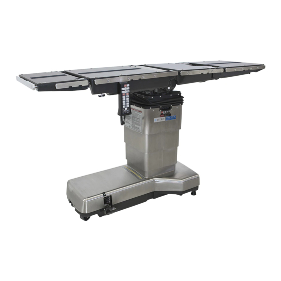
Page 77: Figure 3-1. Amsco 3085 Sp Surgical Table Components (Typical)
Override Rocker Switch Head Down Toward Lower International Symbols Down Foot Pedal AUXILIARY CONTROLS (OVERRIDE SWITCHES) Caster Power Cord Floor Lock Drawings are not to scale POWER CORD FLOOR LOCKS Figure 3-1. Amsco 3085 SP Surgical Table Components (Typical) 764332-898... -
Page 78: Figure 3-2. Side Tilt
This condition results from air becoming entrapped in the hydraulic system. Refer to S 7.28, H ECTION YDRAULIC , for a procedure for YSTEM LEED ROCEDURE bleeding the air from the hydraulic system. If the bleed procedure does not adequately reduce the seat/back section variance, Table Control Software 56400-112 Revision 6 is available to correct the condition. -
Page 79: Figure 3-4. Leg Up And Down
3.3.3.3 Leg Up and Down 0.4 mm Cone See Figure 3-4 and refer to Hydraulic System Schematic (P134469-303) behind R Tab. EFERENCE RAWINGS The leg up and down articulations require the use of two hydraulic cylinders, two lowering brake check valves, one Flow Fuse Valve Flow Fuse Valve three-position directional valve (S3 and S4) and one start/... -
Page 80: Figure 3-5. Flex/Reflex, Trendelenburg/Reverse Trendelenburg And Back Up/Down
the check valve in the lowering brake check valve. This Seat Back allows fluid exiting the back cylinders to flow through the two-position directional valve (S-10S), the piloted lowering brake check valve, the S-7 valve and back to the reservoir. The Reverse Trendelenburg articulation is accomplished by energizing the S-8, S-10 and S-13 (on early motor and pump units) solenoid valves. -
Page 81: Electrical System
The Floor Unlock function is accomplished by energizing the S-11 and S-13 (on early motor and pump units) The Amsco 3085 SP Surgical Table control system is solenoid valves. This allows fluid to flow through the designed for maximum reliability and includes adequate S-11 valve to the retract ports of the floor lock cylinders. -
Page 82: Principles Of Operation
should the primary microprocessor system become 90% battery charge, 36 hours for 95%, and 48 hours for inoperative. 100% charge. A minimum of 36 hours is recommended. The master computer is located on the table column, while The input voltage selector switch on the new (IPX4) power the slave computer is located in the hand control. - Page 83 from the table control to conserve battery life when the Floor-lock microswitch (two) signals are fed into the unit is off, and powers the delay circuit for motor and coil board, which responds by signaling the hand control to enable. The latch relay can also be set (turn power off) indicate floor-lock status and enabling hand control table from the override switch PC board whenever any of the operation.
- Page 84 The hand-control PC board is powered by +5 Vdc from signal is fed to the power-control PC board to turn on the the dc-dc converter on the table-control PC board. hydraulic pump if possible (see note), and to turn off power to the hand control.
-
Page 85: Inspection And Maintenance
WARNING – PERSONAL INJURY HAZARD: A preventive maintenance program is available from When cleaning/disinfecting table, do not STERIS to help ensure peak performance and to avoid use phenolics which may cause patient unscheduled downtime. The program includes skin burns if inadequately rinsed off. -
Page 86: Table 4-1 Preventive Maintenance Schedule For Amsco 3085 Sp Surgical Table
Table 4-1. Preventive Maintenance Schedule for Amsco 3085 SP Surgical Table Minimum Service Required Frequency 1.0 PREPARATION FOR PREVENTIVE MAINTENANCE 1.1 Discuss equipment operation with department personnel. Each Inspection 1.2 Remove pads. Examine pad covers and fastening strips (pads and table). - Page 87 Table 4-1. Preventive Maintenance Schedule for Amsco 3085 SP Surgical Table (Cont’d) Minimum Service Required Frequency 6.0 TABLETOP OPERATION 6.1 Check operation of Return-to-Level function. 2 x per year 6.2 Check operation of back section. 2 x per year 6.3 Check operation of leg section.
-
Page 88: After Each Usage
5. Unplug hand control. Note hand control plug is locked, do not simply pull on plug. After each use of the Amsco 3085 SP Surgical Table, 6. Clean hand control as follows: clean/disinfect as follows: NOTE: Do NOT immerse hand control in liquid. -
Page 89: Weekly Cleaning Procedure
4.3.4 Weekly Cleaning Procedure 4.4.2 Battery-Powered Tables After each weekly use of the Amsco 3085 SP Surgical WARNING – PERSONAL INJURY AND/OR Table, clean/disinfect table as follows: EQUIPMENT DAMAGE HAZARD: Repairs 1. Perform Steps 1 through 4 of S 4.3.2, A... -
Page 90: Reset Circuit Breakers
3. Verify low battery indicator LED is OFF and 2. Pry cartridge out with a small screwdriver to access disconnect ac power. fuses. 3. Remove blown fuse(s) and replace. Refer to 4.5 RESET CIRCUIT BREAKERS Table 4-2 for correct part number of fuses. 4. -
Page 91: Replacement Parts And Supplies
Use of unauthorized parts will void the equipment on your order. warranty. Refer to I LLUSTRATED ARTS REAKDOWN 3. Send your order directly to STERIS Sales and Service Center serving your area. Table 4-2. Amsco 3085 SP Replacement Parts Recommended Description Part Number... -
Page 92: Table 4-3 Recommended Cleaning Products
3) USA fuses are AGC or ABC or MTH, and are also for use in Canada. 4) IEC fuses are IEC glass fuses. IEC F3 and F4 fuses require IEC fuseholder (STERIS part number P129360-654). 5) One spare of the type you use. If your plug is not in this list, order the Power Cord type nearest to your applications, cut the plug off and install your plug in its place. -
Page 93: Troubleshooting
(see • Regularly scheduled preventive Table 5-1). If you can't solve the situation, call STERIS maintenance is required for safe and and give the following information for the table: model reliable operation of this equipment. -
Page 94: Table 5-1 Troubleshooting Guide
Table 5-1. Troubleshooting Guide Situation Cause Service Instructions 1. Cannot turn table ON. Hand control not 1. Hand control not connected - connect. connected or defective. 2. Hand control defective - replace. 2. No power to pump motor: table Table not receiving power. 1. - Page 95 Table 5-1. Troubleshooting Guide (Cont’d) Situation Cause Service Instructions 7. All green, yellow and red LEDs Faulty communications. 1. Check hand control connection. flashing. 2. Replace hand control if necessary. 8. Green ON LED flashing. Control logic error or faulty 1.
- Page 96 Table 5-1. Troubleshooting Guide (Cont’d) Situation Cause Service Instructions 12. Table cannot be turned ON by Electrical system 1. Check table operation using override malfunction. switches - proceed to Situation 13. hand control. 2. Listen for operation of CR3 in power- control assembly when ON/OFF switches are activated - check continuity of ON circuit from hand...
- Page 97 Table 5-1. Troubleshooting Guide (Cont’d) Situation Cause Service Instructions 14. No override switch operation Electrical system 1. Check table operation when line cord when line cord is not plugged in. malfunction. is plugged in - proceed to Situation 13. 2. Check control and motor battery voltages - charge batteries by plugging cord into facility power.
- Page 98 Table 5-1. Troubleshooting Guide (Cont’d) Situation Cause Service Instructions 18. Floor lock LOCK LED does not Electrical system 1. Check LS1 and LS2 switch adjustment come ON. malfunction on back locking legs - adjust switches. 2. Check solder joints at microswitch terminals - resolder as necessary.
-
Page 99: Electrical Troubleshooting
• When resoldering or replacing any of the table or Refer to Table 5-2, Battery Diagnostics, to determine floor-lock microswitches, isolate the control by proper battery voltages (battery-operated tables only). disconnecting its associated plug. Figure 5-1. Amsco 3085 SP Surgical Table Block Diagram 764332-898... -
Page 100: Field Test Procedure
WARNING – PERSONAL INJURY AND/OR EQUIPMENT DAMAGE HAZARD: Repairs and adjustments to this equipment must be made only by STERIS or STERIS-trained service personnel. Maintenance performed by unqualified personnel or installation of unauthorized parts could cause personal injury, result in improper equipment performance, invalidate the warranty or result in costly damage. -
Page 101: Floor Lock Assembly
ahead. Gauge reading should be less than 35 lb (16 kg). 3. With table in same alignment, slowly push at right angles to table centerline, at outboard end of left side rail on table headrest. Gauge reading should be less than 20 lbs (9 kg). 6.6 FLOOR LOCK ASSEMBLY 1. -
Page 102: Table 6-1 Table Articulation Movement And Times
Table 6-1. Table Articulation Movement and Times Movement Time Articulation Note Units Minimum Maximum Minimum Maximum Minimum inches 26.5 27.5 Elevation Maximum inches 43.5 44.5 Elevation Left Tilt degrees 16.0 20.0 Right Tilt degrees 16.0 20.0 Trendelenburg (2, 4) degrees 22.0 27.0 R. -
Page 103: Tabletop Raise/Lower
6.8 TABLETOP RAISE/LOWER 1. Lower table to minimum elevation. Check distance from floor to leveled back top surface (without pad). See Table 6-1. 2. Raise table to maximum elevation. Check distance from floor to leveled back top surface (without pad). See Table 6-1. -
Page 104: Tabletop Limit Switches
recorded right tilt angle from left tilt angle. If 4. If limit switch LS4 does not function as described necessary, adjust cylinder (refer above, check to ensure it is being actuated when 7.17.7, S back section is within 0.5 ±0.3° of its mechanical stop ECTION YLINDER (use TRENDELENBURG function). - Page 105 • Seat Up • Back Up • Leg Down 2. Actuate Return to Level. Tilt, back and seat must return to within 2° of horizontal, and leg section must return to within 2° of seat section. 3. Position tabletop so following positions are at least 10°...
-
Page 106: Component Repair And Replacement
WARNING – PERSONAL INJURY AND/OR EQUIPMENT DAMAGE HAZARD: • Repairs and adjustments to this equipment must be made only by STERIS or STERIS-trained service personnel. Maintenance performed by unqualified personnel or installation of unauthorized parts could cause personal injury, result in improper equipment performance, invalidate the warranty or result in costly damage. -
Page 107: Work Place
NOTE: STERIS suggests letting table sit (without parts. If this is impractical, at least cover open port moving top sections) for at least four hours to permit with a clean, lint-free cloth. -
Page 108: Shroud Removal/ Replacement Procedures
The following procedures are for removing/replacing IPX4 tables are equipped with a low current leakage transformer designed to isolate other the shroud assembly on the Amsco 3085 SP Surgical table electrical assemblies and thus reduce Table. Review all Safety Precautions listed at the current leakage. -
Page 109: Shroud Replacement
screws, then reach inside shroud and unfasten both 7.4.3 Base Shroud Adjustment spring catches. Position the base shroud on the base casting to provide 7. Remove front half of base shroud. the necessary clearance between column components and the base shroud: 8. -
Page 110: Leg Section Adjustment
Loosen cap screws, insert or remove required shim thickness to give maximum UP position of 80°, then tighten cap screws. NOTE: Slightly raise the seat section for better access to the cap screws. d. Repeat Steps b and c for other side. Each side must be 80°... -
Page 111: Seat Section Adjustment
2. Turn cylinder rod into clevis to increase DOWN 3. If tilt angle is not 18 ± 2°, adjust angle as follows: articulation and out to decrease articulation. A 1° WARNING – PERSONAL INJURY HAZARD: change is equal to 1/10 revolution of rod in clevis. The lock mechanism has a high spring 3. -
Page 112: Figure 7-2. Leg Level Position Adjustment Procedure For Return-To-Level
required adjustments made to ensure conformance with the requirements. • If, for any reason after this procedure is complete, the right leg cylinder is replaced, or the right leg cylinder pivot block shims are changed, the Leg Return-to-Level and Leg Full-Up positions must be rechecked and any required adjustments made to ensure conformance with the requirements. -
Page 113: Floor Lock Linkage And Switch Adjustment
NOTE: A change in position of the shaft of 0.020" 3. Turn cylinder rod out of clevis until gap between (0.51 mm) results in an angle change of about 1°. clevis and floor lock housing is 1/8 ± 1/32" (3.2 ± 0.8 mm) •... -
Page 114: Ls4 - Back Section Limit Switch Adjustment
not turn on and no motion should occur. Repeat for 3. Starting with tabletop horizontal, actuate BACK REVERSE TRENDELENBURG. LOWER until motion stops. Verify motion stopped from back limit switch by actuating BACK LOWER 2. With switch released, actuate same functions. When with override control switches located on shroud motion has started, depress switch. -
Page 115: Lash Adjustments
7.16 LASH ADJUSTMENTS NOTE: Do not remove all of the column lash or inadvertently make the column too tight, creating If it has been determined that the table lash needs excessive loads on the bearings and producing adjusted (refer to Step 4, S 6.8, T ECTION ABLETOP... -
Page 116: Hydraulic Cylinder Replacement
4. Lash can occur in any of four bearings; however, 8. Wipe fittings and put them on a lint-free cloth until only certain combinations produce rotational lash: reuse. all four bearings, any three bearings, two head-end 7.17.1.2 Replacement bearings or two foot-end bearings. NOTE: Always replace sealing washers. -
Page 117: Floor Lock, Head End
2. Tighten cylinder rod into shaft and link assembly 7.17.4 Back Section Cylinders (15, 16). Reinstall pivot pin and retaining rings (13, 14). CAUTION – POSSIBLE EQUIPMENT DAMAGE: Do not remove back section 3. Reattach hoses. Tighen retaining nuts on hose cylinder without supporting back section. -
Page 118: Leg Section Cylinders
3. Reattach hose bracket. 11. Using Chapman set, remove two screws and washers (Figure 14, 17 and 18). Remove shims 4. Return both button plugs and dowell pins (Figure 14, 14 and 15). (Figure 13, 6 and 7) attaching cylinder to back section casting. -
Page 119: Side Tilt Cylinder
4. Remove hex head cap screws and flat washers (17 10. Pull cylinder down and away from table. Be and 18) from frame (1). careful not to pull out any electrical plugs. 5. Remove shims (14 and 15) from cylinder (notice 11. -
Page 120: S9 And S10
10. Loosen each solenoid housing using deep socket 11. Replace spool, O-ring, plastic seat and brass (24 mm). With lint free cloth under each housing washer as necessary, noting orientation of each. to catch any leakage, unthread each housing by 12. -
Page 121: S11 And S12
4. If seat section drift still exists after replacing 1. Remove front base shroud as described in spring, replace ball check valve. 7.4, S ECTION HROUD EMOVAL EPLACEMENT ROCEDURES NOTE: All Bieri 3 manifolds currently shipping for 2. Raise table to maximum height. Service parts are equipped with the stiffer spring. -
Page 122: Override Switch Pc Board Assembly
7. Remove bottom screw (16) and washers (17, 20 and 19) holding PC board to column. Switch Panel Mounted Flush to This Surface 8. Remove PC board. Hose Guide Plate May Need Bent in 9. Attach new PC Board Assembly to column. This Area Away From Switch to Remove Any Interference NOTE: Plugs P28 and P29 look alike but are not... -
Page 123: Power Supply Assembly Replacement
6. Press new board onto standoffs, ensure board is 7.21 BATTERY REMOVAL/ firmly snapped into place. REPLACEMENT 7. Reattach plugs P5 and P6. NOTE: The numbers in parentheses () refer to items found 8. Reattach cover to power supply assembly using on Figure 3 located in Illustrated Parts Breakdown (refer to three screws (38) and washers (39). -
Page 124: Transformer Replacement
7. Make wire connections (P19, P20 and P21) to new 7.24 MANUAL PUMP PRIMING battery charger. PROCEDURE 8. Lower new battery charger into table base. NOTE: The numbers in parentheses () refer to items found 9. Secure battery charger with two sems screws (9), on Figure 6 located in Illustrated Parts Breakdown (refer to washers (11) and nuts (10). -
Page 125: Reservoir Filling
7.26 RESERVOIR FILLING • Position table into full BACK UP followed by full BACK DOWN. NOTE: Use only 3080 Series table oil (P764322-636) when • Fully extend and retract Kidney Bridge. adding oil to or refilling reservoir. • Repeat this procedure four more times. 1. - Page 126 NOTE: This procedure is typically completed by Service licensed and permitted hazardous waste personnel outside of North America. management firms. The following materials are contained within the Amsco 3085 SP Table. When disposing of the table or 7-21 764332-898...
- Page 127 • Electronic and Electrical Parts - not known to NOTE: Since each version of the Amsco 3085 SP Surgical require special disposal methods at date of this Table could be slightly different, it is a good idea to take manual.
-
Page 128: Figure 7-7. Remove Pressure Plate
Pressure Setscrews Pressure plate Plate Button Head Screws 1/2" Hex Head Screws Figure 7-7. Remove Pressure Plate 5. Remove column stop screw (see Figure 7-8). Figure 7-10. Left Guide Shaft Screws 8. Secure tabletop (see Figure 7-11) as follows: Column Place sawhorses under back and seat tabletop Stop sections. -
Page 129: Figure 7-12. Loosening Override Relay
Relay Board Loosened Sliding Guide Shaft Out Bearings Felt Oiler Figure 7-12. Loosening Override Relay Figure 7-14. Bearings and Felt Oilers 11. Unlock floor locks to give enough clearance for 13. Remove four bearings adjustment screws. Apply bottom of ram cylinder. Push base so right side Loctite 222 and reinstall them hand tight (see guide shaft clears and gives access to bearings on Figure 7-15). -
Page 130: Figure 7-16. Center Ram
19. Activate loor locks and press raise button so tabletop weight is on ram and just off sawhorses. Remove sawhorse setup. 20. Reinstall pressure plate using Loctite 222 on button head screws. 21. Tighten five setscrews until they just touch left side guide shaft. - Page 131 Live Document, Historical Table Live Document Figure Number/ Name Manual Development Historical Record Page Number P: Stamp “12/16/2011 LIVE DOCUMENT” C: Document Manufacturing Front Cover Front Cover changes/manual errors and clarifications A: Stamped to show Live Document Date Table 2-3 Special Tools for P: Gray Touch-Up Paint (60cc Bottle) has a typo in the part number Amsco 3085SP Surgical Table R: Correct part number is P150824-612...
-
Page 133: Maintenance Instructions
Refer to the accompanying description for specific information GENERAL regarding the part (see Example 1). Assemblies and components of the Amsco 3085 SP 4. The abbreviation A/R means “As Required” or Surgical Table are illustrated and identified on the “Amount Required.”... - Page 134 FIG. & ITEM UNITS PER PART DESCRIPTION ASSEMBLY NUMBER 10-1 P 146667 035 Harmony LA Wall Control Assembly, Domestic......X P 146667 327 Harmony LA Wall Control Assembly, Global........P 146667 358 Harmony LA Wall Control Assembly, LA2 ........P 146667 278 ASSEMBLY, Cover/Membrane Replacement ........
- Page 135 Table 1. Amsco 3085 SP (IPX4) Parts - Quick Reference Guide Description Part Number Reference Loctite, Type 222 R005300-545 Figure 16, Item 36 Adhesives/Supplies Loctite 242, 50 cc R005300-554 Not Shown Loctite 262 (Thread Locker) R005300-890 Not Shown Loctite 271...
- Page 136 Table 1. Amsco 3085 SP (IPX4) Parts - Quick Reference Guide (Cont’d) Description Part Number Reference Assembly, Override (P22, Floor Lock) P134469-092 Figure 6, Item 31 Electrical (Cont’d) Battery, Motor 12 V P764331-223 Figure 3, Item 12 Assembly, Cable (LS1, LS2 and P27)
- Page 137 Table 1. Amsco 3085 SP (IPX4) Parts - Quick Reference Guide (Cont’d) Description Part Number Reference Worm P016234-091 Figure 17, Item 10 Parts (Cont’d) Joint, Universal P020200-045 Figure 17, Item 19 Cylinder, Rubber P021504-091 Figure 2, Item 26 Pin, Grooved, 3/16 x 1...
- Page 138 Table 1. Amsco 3085 SP (IPX4) Parts - Quick Reference Guide (Cont’d) Description Part Number Reference Plug, Pipe (1/4) P129360-580 Figure 9, Item 20 Parts (Cont’d) Pad Set, 2" (3080/3085) P129360-589 Figure 10, Item 27 X-Ray Top Assembly, Head section...
- Page 139 Table 1. Amsco 3085 SP (IPX4) Parts - Quick Reference Guide (Cont’d) Description Part Number Reference Parts Packages Foot Control Switch P764326-690 Not Shown (Cont’d) Foot Control Cord P764326-689 Not Shown Check Valve Kit P150823-727 Figure 23 Column Cylinder Seal...
- Page 140 LIST OF ILLUSTRATIONS Figure 1. 3085 SP (IPX4) Surgical Table Base Shroud and Bellows Support Assembly (1 of 3) ..2 Figure 1. 3085 SP (IPX4) Surgical Table Bellows Mounting Assembly (2 of 3) ..... . 3 Figure 1.
- Page 141 See Sheet 3 of 3 Saddle Bellows Brackets Before S/N B420702025 After S/N B409804078 AVERT See Sheet 2 of 3 Ground Strap Section A-A Figure 1. 3085 SP (IPX4) Surgical Table Base Shroud and Bellows Support Assembly (1 of 3) 764332-899...
- Page 142 Before S/N B420702025 After S/N B409804078 Figure 1. 3085 SP (IPX4) Surgical Table Bellows Mounting Assembly (2 of 3) 764332-899...
- Page 143 * There was a change to the shrouding. Note if your bottom shroud has clips welded on the inside of the upright for the column, individual shroud components are available for this style. The bar frame style components are NLA, a complete set of replacement shrouds will need to be replaced.
- Page 144 LABEL, Hermes-Ready (HERMES Ready Only) ......... A/R A/R A/R P 093909 795 LABEL, Warning .................. P 141210 459 LABEL, Warning .................. P 056397 643 LABEL, STERIS Logo................P 056397 676 LABEL, 120V Setting ................P 056397 678 LABEL, 230/240V Setting (International)..........A/R A/R A/R P 002960 042 NUT, Hex #10-32 .................
- Page 145 UNITS PER FIG. & PART DESCRIPTION ASSEMBLY ITEM NUMBER 3085 SP (IPX4) Surgical Table Bar Style Frame (Cont’d)....3085 SP (IPX4) Surgical Table Clip Style (Before S/N B409804078, With Bellows Mount)......3085SP (IPX4) Surgical Table (After S/N B409804078, Without Bellows Mount) ......P 012539 061 SCREW, Round Head, SS, #10-32 x 3/8 ..........
- Page 146 TIES, Wire (Not Shown)............... 10 10 10 * See Note and Illustration in Figure 1 (3 of 3) ** Item 54 may have the connector on control side; if not contact STERIS Service Engineering. *** Included in Items 1 and 2. 764332-899...
- Page 147 Figure 2. 3085 SP (IPX4) Surgical Table Base Assembly, Floor Lock and Casters (1 of 2) 764332-899...
- Page 148 Tower Style Floor Lock S/N After B427104-145 Housing Style Floor Lock S/N Before B427104-145 Figure 2. 3085 SP (IPX4) Surgical Table Base Assembly, Floor Lock and Casters (2 of 2) 764332-899...
- Page 149 UNITS PER FIG. & PART DESCRIPTION ASSEMBLY ITEM NUMBER 3085 SP (IPX4) Surgical Table Base Assembly, Floor Lock and Casters; Housing Style (Before B427104145) ......3085 SP (IPX4) Surgical Table Base Assembly, Floor Lock and Casters; Tower Style (After B427104145) ........P 056397 570 CASTER, Swivel, 1/2-13, Non-Conductive ..........
- Page 150 Figure 3. 3085 SP (IPX4) Surgical Table Base Assembly, Components 764332-899...
- Page 151 UNITS PER FIG. & PART DESCRIPTION ASSEMBLY ITEM NUMBER 3085 SP (IPX4) Surgical Table Base Assembly, Components Electric Unit..................Battery Unit ..................P 146653 460 COUNTERWEIGHT................P 129359 896 SCREW, Socket Head Cap, 3/8-16 x 3-1/4 ......... P 019680 041 WASHER, Helical Spring, 3/8 ..............
- Page 152 UNITS PER FIG. & PART DESCRIPTION ASSEMBLY ITEM NUMBER 3085 SP (IPX4) Surgical Table Base Assembly, Components (Cont’d) Electric Unit ..................Battery Unit ..................P 141210 543 • PC BOARD, Power Control (For P134469-515 Only)......P 150830 819 • HARNESS, 120 V, Jumper ..............P 764314 447 •...
- Page 153 Figure 4. 3085 SP (IPX4) Surgical Table Base Assembly, Column Mounted Parts 764332-899...
- Page 154 UNITS PER FIG. & PART DESCRIPTION ASSEMBLY ITEM NUMBER 3085 SP (IPX4) Surgical Table Base Assembly, Column Mounted Parts ............... COLUMN ASSEMBLY (see Figure 7 and Figure 8) ......P 134469 528 HOSE, Guide ..................P 200050 303 SCREW, Button Head Cap, #10-32 X 3/8 ........... P 056397 373 CLAMP, Hose ..................
- Page 155 Figure 5. AC Plate Assembly 764332-899...
- Page 156 UNITS PER FIG. & PART DESCRIPTION ASSEMBLY ITEM NUMBER 755717 297 AC Plate Assembly, w/o Labels and Cover (P17) ......AC Plate, Related Parts List ............P 136807 030 ASSEMBLY, Power Control Cable (P17)..........– P 150823 292 CARTRIDGE, 6 Amp Fuse (F1/F2; 100 or 120 Vac) ......–...
- Page 157 Floor Lock Override Cable Assembly Figure 6. Foot Pump Assembly 764332-899...
- Page 158 UNITS PER FIG. & PART DESCRIPTION ASSEMBLY ITEM NUMBER 146653 789 Foot Pump Assembly ............... Foot Pump, Related Parts List ............P 136807 013 PEDAL, Painted ................... – P 136807 008 BRACKET, Pump................. – P 136807 006 BODY, Pump ..................–...
- Page 159 Reference A (Refer to Section 7.25, Column Lubrication) 15 16 17 Figure 7. Column Assembly 764332-899...
- Page 160 UNITS PER FIG. & PART DESCRIPTION ASSEMBLY ITEM NUMBER Column Assembly (S/N Before B413304015) ......... Column Assembly (S/N After B413304015) ........BLOCK, Stage ..................P 146653 433 GUIDE, Column, Pressure Plate............– P 146653 432 SUPPORT, Right Hand................ P 093908 595 GUIDE, Shaft ..................
- Page 161 Figure 8. Column Assembly 764332-899...
- Page 162 UNITS PER FIG. & PART DESCRIPTION ASSEMBLY ITEM NUMBER Column Assembly ................764324 901 * KIT, Column Cylinder Seal............... P 016868 041 SCREW, Socket Head Cap, 3/8-16 x 1 ..........P 019680 041 WASHER, Helical Spring, 3/8 .............. P 056397 238 CAP, Stop ....................
- Page 163 Data Label 2 40 Side Tilt Cylinder Side Tilt Cylinder Seat Cylinder Figure 9. Table Saddle Assembly 764332-899...
- Page 164 UNITS PER FIG. & PART DESCRIPTION ASSEMBLY ITEM NUMBER Table Saddle Assembly (S/N Before B409804078) ......Table Saddle Assembly (S/N After B409804078) ......SADDLE (Not a Service Replacement Part)........– SADDLE (Not a Service Replacement Part)........– CYLINDER, Hydraulic (Seat; see Figure 21) ........CYLINDER, Tilt (see Figure 21)............
- Page 165 Figure 10. Table Tops and Side Rail Assembly 764332-899...
- Page 166 UNITS PER FIG. & PART DESCRIPTION ASSEMBLY ITEM NUMBER Table Tops and Side Rail Assembly ..........P 141210 530 ASSEMBLY, Headrest (see Figure 16)..........P 764324 054 TOP, Back Section................P 764324 055 TOP, Leg Section................. P 093909 539 TOP, Leg Section (Andrews Frame) ........... P 764324 056 TOP, Seat Section ................
- Page 167 UNITS PER FIG. & PART DESCRIPTION ASSEMBLY ITEM NUMBER Table Tops and Side Rail Assembly (Cont’d) ........ P 129360 589 PADS, Set, 2” (Not Shown) P 136806 811 •PAD, Leg Section, 2" (Not Shown) ............. P 136806 813 •PAD, Head Section, 2" (Not Shown)........... P 136806 815 •PAD, Back/Seat Section (Not Shown) ..........
- Page 168 Back Section Head Section Leg Section Seat Section Figure 11. Standard X-Ray Top Assemblies 764332-899...
- Page 169 UNITS PER FIG. & PART DESCRIPTION ASSEMBLY ITEM NUMBER 136807 044 Standard X-Ray Top Assembly, Back Section....... 136807 045 Standard X-Ray Top Assembly, Head Section ......136807 042 Standard X-Ray Top Assembly, Leg Section ......... 136807 043 Standard X-Ray Top Assembly, Seat Section........ P 093909 289 X-RAY TOP, Back Section..............
- Page 170 Figure 12. Tabletop Assembly 764332-899...
- Page 171 UNITS PER FIG. & PART DESCRIPTION ASSEMBLY ITEM NUMBER Tabletop Assembly................ASSEMBLY, Back Section (see Figure 13) ......... P 136807 076 ASSEMBLY, Kidney Bridge and Rack ..........P 003952 041 SCREW, Roundhead, Machine, 1/4-20 x 1/2 ........P 003999 041 SCREW, Roundhead, Machine, 1/4-20 x 5/8 ........
- Page 172 Figure 13. Back Section Assembly 764332-899...
- Page 173 UNITS PER FIG. & PART DESCRIPTION ASSEMBLY ITEM NUMBER Back Section Assembly ..............P 764330 136 KIT, Back Section Assembly..............• BEARING, Olite ................. • BEARING, Headrest Mounting ............P 129360 483 • STICKER, Natural Ground ..............P 090348 061 •...
- Page 174 Figure 14. Seat Section Assembly 764332-899...
- Page 175 UNITS PER FIG. & PART DESCRIPTION ASSEMBLY ITEM NUMBER Seat Section Assembly ..............P 764328 196 FRAME, Seat Section ................ASSEMBLY, Leg Cylinder, L.H. (see Figure 21) ......... ASSEMBLY, Leg Cylinder, R.H. (see Figure 21)......... P 136807 731 ASSEMBLY, Self Level................ P 136807 729 •...
- Page 176 Figure 15. Leg Section Assemblies 764332-899...
- Page 177 UNITS PER FIG. & PART DESCRIPTION ASSEMBLY ITEM NUMBER Leg Section Assemblies P 141210 524 LEG SECTION ASSEMBLY, Left Side ..........P 141210 525 LEG SECTION ASSEMBLY, Right Side..........P 044746 045 SCREW, Cap, 3/8-16 x 1-1/4............... P 019680 041 WASHER, Helical Spring, 3/8 ..............
- Page 178 Right Left Figure 16. Headrest Assembly 764332-899...
- Page 179 UNITS PER FIG. & PART DESCRIPTION ASSEMBLY ITEM NUMBER P 141210 530 Headrest Assembly ................P 764332 915 FRAME, Side, Left Hand..............P 764332 916 FRAME, Side, Right Hand ..............P 150823 276 SPACER, Side Rail, 9/16..............P 093909 366 CAP, Pivot....................
- Page 180 Figure 17. Kidney Bridge Shaft Assembly 764332-899...
- Page 181 UNITS PER FIG. & PART DESCRIPTION ASSEMBLY ITEM NUMBER 146653 926 Kidney Bridge Shaft Assembly (Before S/N 0422310070) .... 146653 926 Kidney Bridge Shaft Assembly (After S/N 0422310070) ....P 136806 486 STABILIZER, Right Hand ..............P 136806 487 STABILIZER, Left Hand............... P 136806 460 BOX, Gear ...................
- Page 182 Before S/N 0422310-007 After S/N 0422310-007 Figure 18. Kidney Bridge Handle Assembly 764332-899...
- Page 183 UNITS PER FIG. & PART DESCRIPTION ASSEMBLY ITEM NUMBER Kidney Bridge Handle Assembly (NLA) Before S/N 0422310-007 ..............056404 064 Kidney Bridge Handle Assembly After S/N 0422310-007 ..............P 136806 457 HANDLE, Kidney Bridge ..............P 056404 063 RATCHET, Handle ................P 093908 662 RATCHET ....................
- Page 184 Figure 19. Table Base and Column: Electrical Assembly (1 of 3) 764332-899...
- Page 185 Hand Control Side Override Switch Side Two Required Per Connector Typical Electrical Connector Tie-Wrap 14 32 View B-B View A Patient Patient Right Left View A Figure 19. Table Base and Column: Electrical Assembly (2 of 3) 764332-899...
- Page 186 Gray Blue Black Figure 19. Table Base and Column: Hermes Electrical Assembly (3 of 3) 764332-899...
- Page 187 UNITS PER FIG. & PART DESCRIPTION ASSEMBLY ITEM NUMBER Table Base and Column Electrical Assembly 3085 SP Table ................3085 SP HERMES-Ready Table ..........P 003153 041 NUT, Hex, #8-32 .................. P 764331 223 BATTERY, 12 V ................... P 030743 045 LOCKWASHER, #4, External Tooth ............
- Page 188 UNITS PER FIG. & PART DESCRIPTION ASSEMBLY ITEM NUMBER Table Base and Column Electrical Assembly (Cont’d) 3085 SP Table ................3085 SP HERMES-Ready Table..........NOT USED P 141210 137 CABLE ASSEMBLY, Leg Section (P36; Not Shown)......P 141210 138 ASSEMBLY, Back Section Cable, (P29, P31, P33, P34 and LS4;...
- Page 189 Power Supply Assembly Screws Nuts and Bolts Supplied With Batteries Figure 20. Electric-to-Battery Conversion (1 of 2) 764332-899...
- Page 190 Figure 20. Electric-to-Battery Conversion (2 of 2) FIG. & PART UNITS PER DESCRIPTION ITEM NUMBER ASSEMBLY 630939 039 Electric-to-battery Conversion............P 764331 223 BATTERY, 12 V..................1 P 426637 598 CHARGER, Battery ................P 093909 212 BRACKET, Battery Support (Coated)..........P 093909 467 JUMPER, Motor Battery ..............
- Page 191 Figure 21. Hydraulic Components Layout 764332-899...
- Page 192 UNITS PER FIG. & PART DESCRIPTION ASSEMBLY ITEM NUMBER Hydraulic Components Layout ............P 141210 304 ASSEMBLY, Control Block Bieri #3 (see Figure 23)......P 134469 149 ASSEMBLY, Column Flange ............... P 056397 274 CYLINDER, Hydraulic, #1, Floor Lock ..........P 056397 275 CYLINDER, Hydraulic, #2 and #3, Floor Lock........
- Page 193 P-35 P-36 Seat (SR), Top Seat (SC), Bottom “R” P-34 P-33 System Pressure Test Port Patient Left Head Figure 22. Table Base and Column: Hydraulic Assembly 764332-899...
- Page 194 UNITS PER FIG. & PART DESCRIPTION ASSEMBLY ITEM NUMBER Table Base And Column Hydraulic Assembly ....... P 150823 398 HOSE, Size 4, 1600 mm (Pressure) ........... P 150823 384 HOSE, Size 2, 1000 mm (FR, FC to Floor Lock Cylinder #1)..P 150823 607 HOSE, Size 2, 950 mm (BR, BC) ............
- Page 195 Unattached End of TC, TR and R 18 19 6 13 Banjo Bolt Hose Sealing Washer Check Valve Assembly (Ball and Spring) Restrictor Ref. View Figure 23. Control Block Assembly 764332-899...
- Page 196 Control Block Ports Hydraulic Control Block Replacement Parts TC,TR,P Opposite 150823-727 Part No. Description s1-13 Control Kit Check Valve Block Side Control Block Assembly (Bieri Hydraulic #3) P141210-304 P150823-369 Banjo Bolt, 10 x 21mm P150823-583 Banjo Bolt, 10 x 25mm P150823-657 Restrictor P150823-727...
- Page 197 Figure 24. Motor and Pump Assembly 764332-899...
- Page 198 UNITS PER FIG. & PART DESCRIPTION ASSEMBLY ITEM NUMBER Motor and Pump Assembly (Metal Reservoir, Bieri #3) ....141210 555 Motor and Pump Assembly (Plastic Reservoir, Bieri #4)....VALVE BOX IV (see Figure 25) ............P 134469 299 MOTOR ....................P 150823 864 * KIT, Metal Reservoir ................
- Page 199 Figure 25. Valve Box IV 764332-899...
- Page 200 UNITS PER FIG. & PART DESCRIPTION ASSEMBLY ITEM NUMBER Valve Box IV ..................P 764330 172 KIT, Solenoid Assembly Rebuild............10 P 150823 380 KIT, Solenoid (S1-S12) ................ P 150823 857 • WASHER, Spring ................A/R P 150823 856 • NUT, Coil ................... A/R P 150823 661 •...
- Page 201 Base Assembly, Column C: Error Mounted Parts A: P14120-549 Item #1 Stage Block is available for STERIS Service Technicians Only. Order Part 7 Column Assembly Number P146653-426 P: How to tell the difference between Andrew's Frame and Basic Side Rail.
- Page 202 Live Document, Historical Table Live Document Figure Number/ Name Manual Development Historical Record Page Number P: Stamp “07/06/2011 LIVE DOCUMENT” C: Document Manufacturing Front Cover Front Cover changes/manual errors and clarifications A: Stamped to show Live Document Date P: Clarify Title of illustration 1 3085SP (IPX4) Surgical C: Clarification Table Bellows Mounting...
-
Page 203: System, Low Leak, Smt Schematic
3085 SP Surgical Table reference drawings. These ® drawings are supplied as an aid in understanding unit operation and troubleshooting. See Table 1 for listing and order of drawings. Table 1. Amsco 3085 SP Surgical Table Technical Drawings Title Sheet Drawing Reference Number...
Need help?
Do you have a question about the Amsco 3085 SP and is the answer not in the manual?
Questions and answers