
Related Manuals for Steris gi4000


Summary of Contents for Steris gi4000
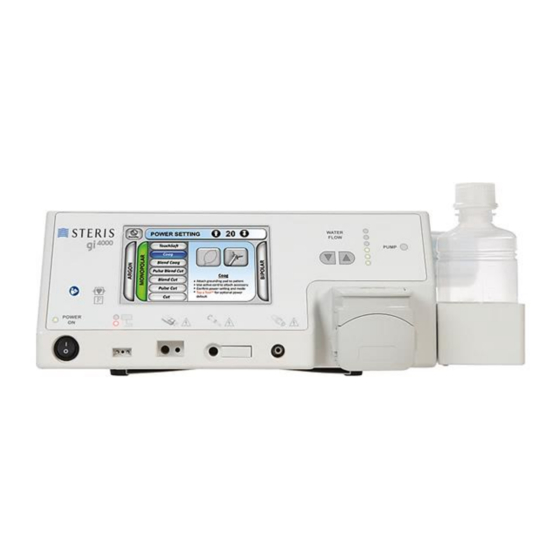
- Page 1 Reference / Reorder No. gi4000 Electrosurgical Unit G1110001 User and Maintenance Manual...
- Page 2 An issued or revision date for these instructions is included for the user’s information. STERIS Endoscopy reserves the right to makes changes to specifications shown herein without notice or obligation. In the event that two (2) years have elapsed between this date and product use, please contact STERIS Endoscopy to determine if additional information is available.
-
Page 3: Table Of Contents
Information for Safety ......................8 Warnings .......................... 9 Precautions ........................19 Notes..........................22 Overview of General Features ..................... 23 gi4000 Electrosurgical Unit .................... 23 7.1.1 Front Panel ......................24 7.1.2 LED Indicator Lights ..................25 7.1.3 Pad Safe System (PSS) ..................26 7.1.4 Touchscreen ...................... - Page 4 8.12 Standards on Electromagnetic Compatibility (EMC) ............. 49 System Installation and Setup ..................... 54 Unpacking the gi4000 ESU .................... 54 Installation - gi4000 ESU ....................54 Installation - GoCart Mobile Cart .................. 56 Setup - Argon Gas System ..................... 57 9.4.1...
- Page 5 10.3.2 Care, Cleaning and Storage ................73 11.0 Recommended Accessories ....................75 11.1 APC Instruments ......................75 11.2 Neutral Electrodes ......................75 11.3 Monopolar and Bipolar Accessories ................75 11.4 Argon Gas Bottle ......................76 11.5 Irrigation Tubing ......................76 11.6 Footswitch ........................
- Page 6 [ This page is intentionally left blank. ]...
-
Page 7: Scope
The ArConnect® argon probe connector is intended for use with the gi4000 ESU during argon assisted coagulation. Contraindications The gi4000 electrosurgical unit has no known contraindications. -
Page 8: Definitions
Definitions Argon Plasma Coagulation Contact Quality Monitoring Electrical Safety Analyzer Electrosurgical Unit Instructions For Use Liquid Crystal Display Light Emitting Diode Low Frequency Magnetic Resonance POST Power On Self-Test Pad Safe System Radiofrequency 00732467 Rev. D Page 2 of 110... -
Page 9: Explanation Of Symbols
Explanation of Symbols Table 5-1 contains symbols which may appear on the gi4000 ESU, gi4000 ESU Footswitch, gi4000 Argon Gas Bottle and GoCart Mobile Cart. Table 5-1 Symbol and SDO (if applicable) Title of Symbol Meaning of Symbol Reference Number ISO 15223-1 Medical 5.1.1... - Page 10 Symbol and SDO (if applicable) Title of Symbol Meaning of Symbol Reference Number ISO 15223-1 Medical 5.3.8 Humidity Limitation Indicates the range of Devices – Symbols to be humidity to which the device used with Medical Device can be safely exposed. Labels, Labelling, and Information to be Supplied (ctd.)
- Page 11 5114 Footswitch Connection Indicates the receptacle by means of which the footswitch is connected to the equipment. This receptacle is ONLY compatible with the gi4000 ESU footswitch. 5140 Non-Ionizing Indicates the equipment Electromagnetic Radiation intentionally applies RF electromagnetic energy for diagnosis or treatment.
- Page 12 Symbol and SDO (if applicable) Title of Symbol Meaning of Symbol Reference Number Unique Device Identifier Indicates the device unique device identifier. Medical Device Indicates the product is a medical device. Contents Indicates the number of devices/kits within the packaging. Return Electrode Indicates the receptacle by Receptacle...
- Page 13 Indicates an operating tip or general information useful for operating or servicing the equipment. Standards Compliance This certification symbol on the gi4000 ESU indicates it is listed by Intertek Testing Services as meeting the requirements of AAMI/ES/IEC 60601-1, IEC 60601-1-2, IEC 60601-1-6, IEC 60601-2-2, CAN/CSA C22.2 No.
-
Page 14: Information For Safety
Information for Safety The following Warnings and Precautions must be observed when installing, operating or performing maintenance on the gi4000 Electrosurgical Unit and Accessories. For emphasis, certain warnings and precautions are repeated throughout this manual. It is important to review ALL warnings and precautions before operating or servicing this equipment. -
Page 15: Warnings
→ Read ALL sections of this manual carefully BEFORE using the gi4000 ESU, such that safety requirements and unit operation are understood. If you... - Page 16 → Increase the separation between the gi4000 ESU and other electrical equipment. → Connect the gi4000 ESU to a receptacle on a different circuit from that to which the other device(s) are connected. WARNING: Personal Injury and/or Equipment Damage Hazard. Check the equipment and accessories each time before using them.
- Page 17 WARNING: Personal Injury Hazard. Any attempt to operate the gi4000 ESU with any gas source other than the gi4000 Argon Gas Bottle, or to attach argon probe accessories ® to the gi4000 ESU in any way other than by the use of the ArConnect argon probe connector may pose a serious hazard to patients and users.
- Page 18 When using the gi4000 ESU, ensure the active accessories and patient/user are not contacting grounded metal objects. If necessary, place dry gauze between the patient and the grounded metal object and continually monitor potential contact points.
- Page 19 Prior to use of the gi4000 ESU on patients with cardiac pacemakers, consult the pacemaker manufacturer or a cardiac specialist for further information.
- Page 20 → If the display fails, the gi4000 ESU can no longer be operated safely. If the touchscreen is non-responsive or no longer visible, immediately stop using...
- Page 21 WARNING: Burn Hazard. Requests for higher power settings or longer activations than normal may indicate a fault exists. → DO NOT increase power settings before all accessories, cables, electrodes and connections are checked. → Apparent low power output at the normal operating settings may indicate faulty application of the dispersive electrode.
- Page 22 / or damage to property and equipment. If this were to occur, the following steps MUST be taken: → Immediately turn the power to the gi4000 ESU OFF and unplug the unit from the main power supply. → Remove the now inactive accessory from the endoscope accessory channel.
- Page 23 WARNING: Venting and Discarding Gas Canisters. DO NOT discard gas canisters that have not been fully vented. Disposal regulations require that canisters be empty before being discarded or recycled. The gi4000 ESU venting cycle is designed to vent the canister to fully empty.
- Page 24 DANGER: Equipment Damage Hazard. Blown line fuses may ONLY be replaced by fuses which have the same rating as the one specified on the rear panel of the gi4000 ESU. Use of incorrect line fuses may result in malfunction or failure of the gi4000 ESU causing a fire or electric shock hazard.
-
Page 25: Precautions
CAUTION: Equipment Damage Hazard. NEVER place the gi4000 ESU on top of other electrical equipment due to its fluid handling system. → DO NOT place the sterile water bottle on top of the gi4000 ESU. Utilize the Water Bottle Holder provided for securing water bottles during use. - Page 26 Sensing/Non-Split dispersive electrodes. Other dispersive electrode products may result in patient or user injury and/or product damage. → In order for all safety aspects of the gi4000 Pad Safe System (PSS) to operate, Sensing/Split dispersive electrodes must be used. Non-Sensing/Non-Split dispersive electrodes are acceptable if used with proper user care.
- Page 27 CAUTION: Incompatibility Hazard. The instructions contained in the operating manuals of any equipment to be used in conjunction with the gi4000 must be followed to avoid a possible hazard from incompatibility.
-
Page 28: Notes
NOTE: When a Fault displays on the screen, reset the gi4000 ESU by turning the power ON/OFF switch OFF and back ON. If the Fault clears the screen, the gi4000 ESU can be put back into service. If the Fault does not clear from the screen, contact STERIS Customer Service at 1-800-769-8226 or your local STERIS Endoscopy Electrosurgery Specialist for a repair or replacement. -
Page 29: Overview Of General Features
The output characteristics of the different methods and modes are adjustable via the touchscreen display located on the front of the unit. • The gi4000 ESU irrigation pump allows for the delivery of a variable pressurized lavage to improve visualization during endoscopic procedures. •... -
Page 30: Front Panel
7.1.1 Front Panel Figure 7-1 1. Power ON/OFF Switch 2. Power ON Light 3. Touchscreen Display 4. Lavage Pump Flow Adjustment Buttons 5. Lavage Pump Flow Indicator Lights 6. Lavage Pump ON Light 7. Argon Gas Bottle with Grip 8. Pump Head Lid 9. -
Page 31: Led Indicator Lights
7.1.2 LED Indicator Lights Power ON LED Indicator Light When the gi4000 ESU is connected to the AC mains power POWER supply source and the power ON/OFF switch is in the ON position (denoted by an “I”), a GREEN LED located above the power ON/OFF switch will illuminate. -
Page 32: Pad Safe System (Pss)
7.1.3 Pad Safe System (PSS) The gi4000 ESU is equipped with the Pad Safe System (PSS), assuring adequate contact between the patient and the dispersive electrode. This system constantly monitors patient/pad contact resistance when used with a sensing/split dispersive electrode and will prevent output if contact falls below a safe level, reducing the risk of thermal injuries to the patient. - Page 33 A YELLOW PSS indicator light is displayed when a Non-Sensing/Non-Split dispersive electrode is connected to the gi4000 ESU. When the PSS light is YELLOW, the operator is prompted to proceed with additional caution as all safety features of the PSS are not active with Non-Sensing/Non-Split dispersive electrodes.
-
Page 34: Touchscreen
Various Fault, Warning and Information boxes will appear with appropriate audible tones when indicated either by use error or condition of the unit. Audible tones can NOT be disabled on the gi4000 ESU for safety reasons. See section 12.1 On-Screen Notifications for a list of all on-screen notifications. -
Page 35: Standby Mode
Standby Mode can be activated and deactivated either by the standby button on the gi4000 ESU footswitch or the standby icon on the upper left- hand side of the touchscreen display. The standby icon is visible in all methods/modes. When Standby Mode is activated, a standby screen will appear on the touchscreen display. -
Page 36: Argon Gas System
Figure 7-11 When using Argon Method, the argon gas for the gi4000 ESU is exclusively supplied by the STERIS Endoscopy argon gas bottle. Each bottle contains 49 liters of ultra-high purity (99.999% pure) argon gas (certified). Argon, an inert gas, is heavier than air with a NFPA rating of zero flammability and zero reactivity. -
Page 37: Footswitch
7.1.7 Footswitch The gi4000 footswitch is used to activate both radiofrequency (RF) electrical energy and lavage flushing with the Power ON/OFF Pedal and the Irrigation Pedal, respectively. Both power and irrigation can NOT be active at the same time. Standby Mode is activated and released by the black, circular button located between the pedals. -
Page 38: Back Panel
7.1.8 Back Panel Figure 7-13 1. Vent Ports 2. Footswitch Receptacle 3. Equipotential (Grounding) Terminal 4. AC Mains Connector with Integrated Fuses and Cord Lock 5. Speaker Ports 00732467 Rev. D Page 32 of 110... -
Page 39: Bottom Panel
7.1.9 Bottom Panel 1. Non-Slip Rubber Feet (x4) 2. Information Tray 3. Vent Ports Figure 7-14 00732467 Rev. D Page 33 of 110... -
Page 40: Gocart Mobile Cart
GoCart Mobile Cart The gi4000 ESU may be placed on the STERIS Endoscopy GoCart Mobile Cart for easy transport and use. It includes two (2) accessory baskets, ergonomic push handles and easy rolling casters with locks and wall deflectors. NOTE: The GoCart Mobile Cart is sold separately. To order, please contact... -
Page 41: Technical Specifications
Service Life: 7 Years Equipotential Ground Connection: An equipotential ground connection is provided to allow connection of the gi4000 ESU to a common ground by way of a potential equalization connector. This connection meets IEC 60601-1 requirements. Classifications Type of Protection Against... -
Page 42: Dimensions And Weight
59 to 77°F (15 to 25°C) prior to use. Storage Duration: If the gi4000 ESU has been stored for a period greater than one (1) year, the unit must be inspected for performance and safety prior to use. Reference section 13.1 Maintenance and Repair: Periodic Inspection or... -
Page 43: Audio
100 V~ 5.0A 120 V~ 4.0A 240 V~ 2.0A Power Cord: ONLY use STERIS Endoscopy provided Power Cords Nominal Input Current Characteristics gi4000 ESU, 120V~ 50/60 Hz Idle 0.40A Coag (120 watts with 200 ohms) 1.5A Cut (200 watts with 200 ohms) 3.5A... -
Page 44: Output Power
Output Power General Output Characteristics Less than 5% All modes (output variation as a function of line voltage variations): Maximum Output Power (Cut Mode into 500 ohms): 240W Output Frequency Range: 315-550 kHz Maximum Output Peak Voltage (Open Circuit ARGON Mode): 4750V Output Characteristics by Mode Table 8-1... -
Page 45: Duty Cycle
Duty Cycle Generator power is continuously ON when the unit is powered ON. All modes under maximum power settings and rated load conditions (monopolar modes: 500Ω, bipolar mode: 100Ω) have an output activation time of 10 sec ON / 30 sec OFF. 8.10 Leakage Low Frequency (50-60 Hz) Leakage Current Chassis to Neutral... -
Page 46: Monopolar Cut Mode
8.11.1 Monopolar Cut Mode CUT Mode Power vs Load Resistance CUT 200 CUT 100 Default 35 100 200 300 400 500 600 700 800 900 1000 1100 1200 1300 1400 1500 1600 1700 1800 1900 2000 Load Resistance Figure 8-1 CUT Mode Output Power vs. -
Page 47: Monopolar Pulse Cut Mode
8.11.2 Monopolar Pulse Cut Mode Pulse CUT Mode Power vs Load Resistance Pulse CUT Pulse CUT Pulse CUT Default 35 900 1000 1100 1200 1300 1400 1500 1600 1700 1800 1900 2000 Load Resistance Figure 8-4 Pulse CUT Mode Output Power vs. Power Setting into 300 ohm Load Power Setting Figure 8-5 Figure 8-6... -
Page 48: Monopolar Blend Cut Mode
8.11.3 Monopolar Blend Cut Mode Blend CUT Mode Power vs Load Resistance Blend CUT Blend CUT Blend CUT Default 35 900 1000 1100 1200 1300 1400 1500 1600 1700 1800 1900 2000 Load Resistance Figure 8-7 Blend CUT Mode Output Power vs. Power Setting into 500 ohm Load Power Setting Figure 8-8 Figure 8-9... -
Page 49: Monopolar Pulse Blend Cut Mode
8.11.4 Monopolar Pulse Blend Cut Mode Pulse Blend CUT Mode Power vs Load Resistance Pulse Blend CUT120 Pulse Blend CUT 60 Pulse Blend CUT Default 900 1000 1100 1200 1300 1400 1500 1600 1700 1800 1900 2000 Load Resistance Figure 8-10 Pulse Blend CUT Mode Output Power vs. -
Page 50: Monopolar Blend Coag Mode
8.11.5 Monopolar Blend Coag Mode Blend COAG Mode Power vs Load Resistance Blend COAG 120 Blend COAG 60 Blend COAG Default 20 100 200 300 400 500 600 700 800 900 1000 1100 1200 1300 1400 1500 1600 1700 1800 1900 2000 Load Resistance Figure 8-13 Blend COAG Mode... -
Page 51: Monopolar Coag Mode
8.11.6 Monopolar Coag Mode COAG Mode Power vs Load Resistance COAG 120 COAG 60 COAG Default 20 200 300 400 600 700 900 1000 1100 1200 1300 1400 1500 1600 1700 1800 1900 2000 Load Resistance Figure 8-16 COAG Mode Output Power vs. -
Page 52: Monopolar Touchsoft® Mode
8.11.7 Monopolar TouchSoft® Mode TouchSoft Mode Power vs Load Resistance Soft COAG Soft COAG Soft COAG Default 50 900 1000 1100 1200 1300 1400 1500 1600 1700 1800 1900 2000 Load Resistance Figure 8-19 Figure 8-20 TouchSoft Mode Output Power vs. Power Setting into 100 ohm Load Power Setting Figure 8-21 00732467 Rev. -
Page 53: Monopolar Argon Method
8.11.8 Monopolar Argon Method ARGON Mode Power vs Load Resistance ARGON ARGON Default 60 200 300 400 600 700 900 1000 1100 1200 1300 1400 1500 1600 1700 1800 1900 2000 Load Resistance Figure 8-22 ARGON Mode Output Power vs. Power Setting into 500 ohm Load Power Setting Figure 8-23 Figure 8-24... -
Page 54: Bipolar Method
8.11.9 Bipolar Method Figure 8-25 Figure 8-26 Figure 8-27 00732467 Rev. D Page 48 of 110... -
Page 55: Standards On Electromagnetic Compatibility (Emc)
Guidance and Manufacturer’s Declaration Table 8-1: Guidance and Manufacturer’s Declaration – Electromagnetic Emissions The gi4000 ESU is intended for use in the electromagnetic environment specified below. The user should assure that it is used in such an environment. Table 8-1 Electromagnetic Environment –... - Page 56 Table 8-2: Guidance and manufacturer’s declaration – electromagnetic immunity The gi4000 ESU is intended for use in the electromagnetic environment specified below. The user should assure that it is used in such an environment. Table 8-2 Electromagnetic Environment – Immunity Test...
- Page 57 RF transmitters, an electromagnetic site survey should be considered. If the measured field strength in the location in which the gi4000 system is used exceeds the applicable RF compliance level above, the gi4000 system should be observed to verify normal operation. If abnormal performance is observed, additional measures may be necessary, such as re-orienting or relocating the gi4000 system.
- Page 58 The gi4000 ESU is intended for use in an electromagnetic environment in which radiated RF disturbances are controlled. The user can help prevent electromagnetic interference by maintaining a minimum distance between portable and mobile RF communications equipment (transmitters) and the gi4000 ESU as recommended below, according to the maximum output power of the communications equipment.
- Page 59 Safe and efficacious use of the gi4000 is directly controlled by the physician or the operating personnel and when in a non-activated state poses negligible risk to the patient, surgical staff or environment.
-
Page 60: System Installation And Setup
3. Review content in section 7.0 Overview of General Features to familiarize yourself with the gi4000 system and its features. 4. The gi4000 ESU should be placed on a stable, horizontal surface. If a mobile cart is to be used, be certain that it provides adequate stability and strength to support the electrosurgical unit and accessories. - Page 61 → If the display fails, the gi4000 ESU can no longer be operated safely. If the touchscreen is non-responsive or no longer visible, immediately stop using...
-
Page 62: Installation - Gocart Mobile Cart
ESU. 2. Lock the front caster wheels by engaging the brake on the front wheels. 3. The shelf of the GoCart Mobile Cart is shaped like the gi4000 ESU. The front of the cart is denoted by the smaller handle. -
Page 63: Setup - Argon Gas System
Setup - Argon Gas System 9.4.1 Argon Gas Bottle Indicator Icons When using the Argon Method, the touchscreen display provides graphical indication of the argon gas bottle status, as shown in Figure 9-2. Figure 9-2 The Argon Gas Bottle is not detected. The Argon Gas Bottle is detected and full. -
Page 64: Installing Argon Gas Bottle
2. Remove the red cap from the argon gas bottle and discard. 3. Turn the gi4000 ESU ON by pushing the power ON/OFF switch to the ON position (the “I” should be pressed inward). 4. Select the Argon Method on the touchscreen display. -
Page 65: Replacing Empty Argon Gas Bottle
ESU between procedures, only when empty. When the argon gas bottle is removed from the gi4000 ESU system, the user will hear the release of residual argon gas from the argon system. -
Page 66: Setup - Lavage Pump
The integrated lavage pump is controlled by the flow adjustment buttons located to the right of the touchscreen display. Whenever the gi4000 ESU is powered ON, the lavage pump is active. The pump activates at a default flow rate, and the flow rate is user controlled by up and down buttons shown by the flow rate indicator lights. - Page 67 Figure 9-5 3. To adjust the pump head to accommodate a different irrigation tubing size, move the dials on BOTH sides of the pump head until the 1.6 pointer indicates the size of tubing that is desired. Tubing Inner Diameter Tubing Wall Thickness Figure 9-6 00732467 Rev.
-
Page 68: Using The Gi4000
10.0 Using the gi4000 NOTE: During use of the gi4000 ESU, the user should be within three to five feet of the unit to interact with the touchscreen display and unit features. NOTE: During the POST, do not touch the touchscreen display. - Page 69 Power the gi4000 ESU ON by pushing the power ON/OFF switch located at the lower left of the unit. The system will go through the Power ON Self-Test (POST) and, if successful will default to the Monopolar Method in Coag Mode.
-
Page 70: Lavage Function
NOTE: During use of the gi4000 ESU, the user should be within three to five feet of the unit to interact with the touchscreen display and unit features. 00732467 Rev. D... - Page 71 Continue to depress the footswitch for a few seconds. After sterile water begins to flow from the distal end of the endoscope, adjust the flow rate controls to obtain the desired flow rate for the procedure. WARNING: Patient Injury Hazard. The user should assess the condition of the patient and use clinical judgement to set the irrigation flow rate to a suitable level to avoid patient injury.
-
Page 72: Procedural Use
Watt increments, or use the DOWN arrow to decrease the power in single Watt increments. The gi4000 ESU comes equipped with factory suggested DEFAULT SETTINGS. All power defaults listed in Table 10-1 are suggested ranges for typical use denoted in watts (W). The final power output chosen must always be the decision of the physician. -
Page 73: Tap-A-Tool™ Software
10.2.2 Tap-a-Tool™ Software Optionally, the user can see and use alternative default power settings for a particular pictured accessory by engaging the Tap a Tool™ software feature. To do so, the user simply touches the picture of the accessory (tool) of choice. The picture’s background will change color reflecting the selection, as shown in Figure 10-2 Deselecting, by simply touching the picture once again, returns the user to the all accessory default setting. -
Page 74: Warning And Information System
10.2.4 Monopolar Method The gi4000 ESU is controlled by the user via the touchscreen display. There are three (3) user selectable electrosurgical output methods: Monopolar, Bipolar and Argon. The Monopolar Method has seven (7) subset Modes: TouchSoft®, Coag, Blend Coag, Pulse Blend Cut, Blend Cut, Pulse Cut and Cut. - Page 75 The dispersive electrode warning must be corrected for operation to resume. In order for all safety aspects of the gi4000 Pad Safe System (PSS) to operate, sensing or 'split' models of patient dispersive electrodes must be used. Non-split or non-sensing patient dispersive electrodes are acceptable if used with proper care.
-
Page 76: Bipolar Method
The gi4000 Bipolar Method is designed to provide a bipolar output ideal for flexible endoscopic bipolar hemostasis probes. The unit is designed with a standard GI bipolar single jack receptacle. -
Page 77: Argon Method
Bipolar Method. 6. Insert the bipolar instrument in the endoscope accessory channel. 7. Exit Standby Mode by pressing the touchscreen display or button on the gi4000 footswitch. 8. Confirm settings on touchscreen before proceeding with procedure. -
Page 78: Using The Gocart Mobile Cart
(i.e. torn insulation, exposed wire, blocked argon gas tube). If any irregularities are noted, DO NOT use the device. 6. Attach the ArConnect® argon probe connector to the gi4000 ESU by inserting it into the ArConnect® probe connector receptacle and LIFTING UP until an audible click is heard, confirming a positive connection. -
Page 79: Post-Procedural Shut Down
10.3 Post-Procedural Shut Down 10.3.1 Disconnecting Accessories 1. At the end of the procedure, put the gi4000 in Standby Mode and remove all accessories from the patient. 2. Once all accessories have been removed from the patient, exit Standby Mode. - Page 80 (1) year. Allow the gi4000 to remain at room temperature for at least three (3) hours if it has been stored at extreme temperatures. Refer to section 8.5 Technical Specifications: Environmental Transport and Storage Parameters for additional information on storing the gi4000 ESU and accessories.
-
Page 81: Recommended Accessories
11.0 Recommended Accessories The gi4000 ESU is designed for use with devices and neutral electrodes from many different manufacturers. Always verify STERIS Endoscopy devices and devices from other manufacturers for compatibility with the output voltages of each method/mode BEFORE use. -
Page 82: Argon Gas Bottle
11.4 Argon Gas Bottle The gi4000 ESU features a proprietary integrated argon gas system which is only compatible with the STERIS Endoscopy gi4000 Argon Gas Bottle. 11.5 Irrigation Tubing The gi4000 ESU lavage pump adapts to various sizes of irrigation tubing currently available to the flexible endoscopy market. -
Page 83: Troubleshooting
12.0 Troubleshooting NOTE: When a Fault displays on the screen, reset the gi4000 ESU by turning the Power ON/OFF Switch OFF and back ON. If the Fault clears the screen, the gi4000 can be put back into service. If the Fault does not clear from the screen, contact... - Page 84 Medium Priority Check Argon Gas Bottle appear, remove the bottle by turning counterclockwise and take it out of the gi4000. Inspect the brass threads for damage. If the threads are undamaged, while using gloved hands, pour a few drops of sterile water onto clean gauze and lightly wipe around the brass threads.
- Page 85 High Priority Method and push PURGE. If the fault does not failure. reappear, the gi4000 is OK to use. If POST is not Contact Technical Services. successful or if purging triggers the fault screen, contact STERIS Customer Service for equipment service.
- Page 86 Turn off and let cool down. Do not touch the Touchscreen during POST. Power FAULT: OFF/ON. If the fault does not reappear, the gi4000 Touchscreen circuit failure. High Priority is OK. If POST is not successful or if the fault Contact Technical Services.
-
Page 87: Troubleshooting
Touchscreen is illuminated Touchscreen calibration required. Contact STERIS Customer but unresponsive. Service. Check the Footswitch connection on the back of the gi4000. Align the Footswitch does not red dot on the Footswitch Connector with the red dot on the Footswitch operate. - Page 88 O-ring. Insert ArConnect® argon probe into the gi4000 ESU by pushing in and lifting up until an audible click is heard, confirming a positive connection. Increase power in increments of two until the desired arc is achieved.
-
Page 89: Maintenance And Repair
Only these recommended maintenance procedures should be followed. A listing of the safety precautions to be observed when operating and servicing the gi4000 ESU can be found in section 6.0 Information for Safety. Do not operate or service this equipment until you have become familiar with this information. -
Page 90: Periodic Inspection
13.1 Periodic Inspection The gi4000 should be visually inspected at least every six (6) months. This inspection should include checks for: Damage to the gi4000. Damage to the power cord. Damage to the power cord receptacle or the cord lock. -
Page 91: Device Inspection Procedure
7. Inspect the speaker ports for any dust or debris. Clean by wiping with cloth or spray with air/vacuum, if necessary. Bottom Panel Inspection 1. Inspect the bottom panel of the gi4000 for major scratches, indentations, cracks, dust and debris. 2. Ensure that all four (x4) non-slip rubber feet are present and secured to the bottom of the unit. -
Page 92: Electrical Safety Test Procedure
5. Using test leads, connect the gi4000 equipotential ground connector on the rear panel of the gi4000 ESU to the input receptacle on the front panel of the ESA. 6. Record the measured value from the ESA on the 00732974 Preventative Maintenance Test Data Summary Sheet –... - Page 93 3. Using test leads, connect the gi4000 equipotential ground connector on the rear panel of the gi4000 ESU to the input receptacle on the front panel of the ESA. 4. Measure the earth leakage in the following three (3) test conditions: Normal Condition - NORMAL POLARITY, CLOSED NEUTRAL, CLOSED EARTH Single Fault Condition No.
- Page 94 4. Using the alligator clip, connect the gi4000 equipotential ground connector on the rear panel of the gi4000 ESU to the input receptacle on the front panel of the ESA. 5. Measure low frequency (LF) leakage current between the chassis of the gi4000 ESU...
- Page 95 4. Connect the test lead to the patient lead receptacle on the ESA. 5. Measure low frequency (LF) leakage current between the active portion of the argon receptacle on the gi4000 ESU and the ESA in the following two (2) test conditions: Normal Condition Test - NORMAL POLARITY, CLOSED NEUTRAL, OPEN EARTH.
- Page 96 2. Connect the 8-mm to 4-mm monopolar test adaptor to the Monopolar Receptacle on the front panel of the gi4000 ESU. 3. Connect the test lead to the monopolar test adaptor on the front panel of the gi4000 ESU. 4. Connect the test lead to the patient lead receptacle on the ESA.
- Page 97 4. Connect the bipolar test leads into the two (2) patient lead receptacles on the ESA. 5. Measure low frequency (LF) leakage current between the Bipolar Receptacle on the gi4000 ESU and the ESA in the following two (2) test conditions: Normal Condition Test - NORMAL POLARITY, CLOSED NEUTRAL, OPEN EARTH.
- Page 98 5. Record the measured value from the ESA on the 00732974 Preventative Maintenance Test Data Summary Sheet – gi4000 ESU. 6. Disconnect the test leads from the PPS Receptacle on the front panel of the gi4000 ESU and from the patient lead receptacles on the ESA.
- Page 99 5. Connect the ground lead to the earth connector on the ESU Analyzer and the ground terminal on the rear panel of the gi4000. 6. Connect a dummy dispersive electrode test lead to the PSS Receptacle on the gi4000 ESU (to receive yellow indicator), as shown in Figure 13-11 below.
- Page 100 Figure 13-10: RF Leakage Measurement Test Diagram – Argon Active and Dispersive Figure 13-11: RF Leakage Measurement Test Diagram – Dispersive Electrode 00732467 Rev. D Page 94 of 110...
- Page 101 8. Connect the earth ground lead to the earth ground input receptacle on the ESU Analyzer. 9. Connect a dummy dispersive electrode test lead to the PSS Receptacle on the gi4000 ESU (to receive yellow indicator), as shown in Figure 13-12 below.
- Page 102 Figure 13-13: RF Leakage Measurement Test Diagram – Dispersive Electrode Radiofrequency Leakage Current Test – Bipolar 1. Select the Bipolar Method menu on the gi4000 ESU touchscreen display. 2. Reference Figure 13-14 below. 3. Connect the Bipolar Test Adaptor to the Bipolar Receptacle on the front panel of the gi4000 ESU.
- Page 103 Figure 13-14: RF Leakage Measurement Test Diagram – Bipolar Active Figure 13-15: RF Leakage Measurement Test Diagram – Bipolar Dispersive 00732467 Rev. D Page 97 of 110...
- Page 104 5 Ω until you reach 130 Ω. When the measurement device reaches 130 Ω, increase resistance on the measurement device in increments of 1 Ω until the gi4000 ESU emits an audible alarm and a Sensing-Pad error message appears on the touchscreen display.
-
Page 105: Rf Output Test Procedure
1. Connect the gi4000 ESU footswitch to the Footswitch Receptacle on the rear panel of the gi4000 ESU. 2. Connect the power cord to the power cord receptacle on the rear panel of the gi4000 ESU. Then, plug the gi4000 power cord into a grounded AC mains outlet with appropriate input ratings as listed in section 8.7 Input Power of this manual. - Page 106 BLEND CUT e. CUT 13. Reference 00732974 Preventative Maintenance Test Data Summary Sheet – gi4000 ESU for applicable test settings for each monopolar mode. 14. Record the measured value from ESU Analyzer for each mode at each output power setting on the 00732974 Preventative Maintenance Test Data Summary Sheet –...
- Page 107 This connection will allow the technician to properly measure Bipolar RF Output. 1. Follow steps 1-4 of the Monopolar RF Output Test procedure to set-up the gi4000 ESU and ESU Analyzer. 2. Select the Bipolar Method menu on the gi4000 ESU touchscreen display.
- Page 108 Argon RF Output Test 1. Disconnect the Bipolar Test Adapter from the ESU Analyzer and the gi4000. 2. Select the Argon Method on the gi4000 ESU touchscreen display. 3. Install the Argon Gas Bottle by inserting it valve end first into the Argon Bottle Receptacle, as shown in Figure 13-19 below.
- Page 109 Figure 13-21: Argon RF Output Test Diagram 00732467 Rev. D Page 103 of 110...
-
Page 110: Internal Argon Gas Filter Replacement
Figure 13-22 Argon Filter Replacement 1. Ensure the gi4000 is powered OFF and the power cord is disconnected from the wall outlet and the power cord receptacle on the rear panel of the unit. 2. Remove all cover screws. - Page 111 Figure 13-24 6. Remove old filter by turning luer lock connection counterclockwise. 7. Install new filter by threading luer fittings into filter ends and secure by turning clockwise. Ensure that the molded text on the filter is facing the IN label on the argon tubing, as shown in Figure 13-25.
-
Page 112: Service Menu
13.3 Service Menu The gi4000 is equipped with a service area. Additional service, setting and maintenance information is available to be viewed on the touchscreen display when this area is accessed. 13.3.1 Accessing Service Menu To access the service information menu: 1. -
Page 113: Factory Default Power Settings
All values are outside most common use, but within a range of possibility. The gi4000 will not preclude a physician choosing a value outside of these DEFAULT limits on a per case basis using the UP/DOWN arrow keys on the Power Bar. -
Page 114: Pump Head Replacement
13.4 Pump Head Replacement 1. Switch the power ON/OFF switch to the OFF position (denoted by “O” on the switch). 2. Disconnect the power cord from the main supply source and the rear panel of the unit. 3. Detach the pump head by depressing and holding the pump head release lever and then rotating the pump head 45°... -
Page 115: Fuse Replacement
Figure 13-31 Figure 13-30 13.5 Fuse Replacement 1. Switch the power ON/OFF switch to the OFF position (denoted by “O” on the switch, switch should not be illuminated). 2. Disconnect the power cord from the wall outlet and the rear panel of the unit. 3. -
Page 116: Service Parts
Disposal regulations require that argon gas bottles be empty before being discarded or recycled. The gi4000 ESU venting cycle is designed to vent the argon gas bottle to fully empty. To vent and remove the Argon Gas Bottle, reference section 9.4.3 Replacing Empty Argon Gas Bottle.
Need help?
Do you have a question about the gi4000 and is the answer not in the manual?
Questions and answers