Rockwell Automation Allen-Bradley Ultra3000 Migration Manual
Hide thumbs
Also See for Allen-Bradley Ultra3000:
- Migration manual (90 pages) ,
- Manual (80 pages) ,
- Integration manual (180 pages)
Table of Contents
Advertisement
Quick Links
Ultra3000 to Kinetix 5100
Servo Drives Migration Guide
Catalog Numbers 2198-E1004-ERS, 2198-E1007-ERS,
2198-E1015-ERS, 2198-E1020-ERS, 2198-E2030-ERS,
2198-E2055-ERS, 2198-E2075-ERS, 2198-E2150-ERS,
2198-E4004-ERS, 2198-E4007-ERS, 2198-E4015-ERS,
2198-E4020-ERS, 2198-E4030-ERS, 2198-E4055-ERS,
2198-E4075-ERS, 2198-E4150-ERS
Reference Manual
Original Instructions
Advertisement
Table of Contents

Related Manuals for Rockwell Automation Allen-Bradley Ultra3000


Summary of Contents for Rockwell Automation Allen-Bradley Ultra3000
- Page 1 Ultra3000 to Kinetix 5100 Servo Drives Migration Guide Catalog Numbers 2198-E1004-ERS, 2198-E1007-ERS, 2198-E1015-ERS, 2198-E1020-ERS, 2198-E2030-ERS, 2198-E2055-ERS, 2198-E2075-ERS, 2198-E2150-ERS, 2198-E4004-ERS, 2198-E4007-ERS, 2198-E4015-ERS, 2198-E4020-ERS, 2198-E4030-ERS, 2198-E4055-ERS, 2198-E4075-ERS, 2198-E4150-ERS Reference Manual Original Instructions...
- Page 2 If this equipment is used in a manner not specified by the manufacturer, the protection provided by the equipment may be impaired. In no event will Rockwell Automation, Inc. be responsible or liable for indirect or consequential damages resulting from the use or application of this equipment.
-
Page 3: Table Of Contents
Kinetix 5100 Drive System Architecture ......77 Rockwell Automation Publication 2198-RM003B-EN-P - November 2020... - Page 4 ..............93 Rockwell Automation Publication 2198-RM003B-EN-P - November 2020...
-
Page 5: Preface
Added Figure 24 and Table 54, dimensions for Ultra3000 400V-class drives. Added Figure 35 Typical Power Wiring of Ultra3000 System (2098-DSD-HVxxx-xx and - HVxxxX-xx). Added Sample Code Library information to the Kinetix 5100 Drive Controlled Via Explicit Messaging section. Rockwell Automation Publication 2198-RM003B-EN-P - November 2020... -
Page 6: Overview
Motion Analyzer is available online at https://motionanalyzer.rockwellautomation.com/. As products mature throughout the product lifecycle, Rockwell Automation® is Migration Services there as your partner to help you get the most out of your current equipment, to help you determine your next steps, and to help you lay out a plan for the transition to newer technology. -
Page 7: Additional Resources
(HF) bonding, the Ground Plane principle, Reference Manual, publication GMC-RM001. and electrical noise reduction. Provides declarations of conformity, certificates, Product Certifications website: rok.auto/certifications and other certification details. You can view or download publications at rok.auto/literature. Rockwell Automation Publication 2198-RM003B-EN-P - November 2020... - Page 8 Notes: Rockwell Automation Publication 2198-RM003B-EN-P - November 2020...
- Page 9 The servo drive receives commands from the Logix controller through the EtherNet/IP network connection. Commands I/O mode are issued through the Add-On_Profile (AOP) with Add-On Instruction (AOI) instructions in the Logix Designer application. Rockwell Automation Publication 2198-RM003B-EN-P - November 2020...
-
Page 10: Kinetix 5100 Servo Drive Catalog Numbers
3 PH 6.05 15.11 2198-E4020-ERS 342…528 3 PH 7.42 20.78 2198-E4030-ERS 342…528 3 PH 13.95 26.08 2198-E4055-ERS 342…528 3 PH 24.8 37.65 2198-E4075-ERS 342…528 3 PH 31.0 53.32 2198-E4150-ERS 342…528 3 PH 41.26 70.14 Rockwell Automation Publication 2198-RM003B-EN-P - November 2020... - Page 11 5…2000 Hz @ 2.5 g peak, 0.0006 mm (0.015 amplitude, continuous displacement Vibration in.) max displacement 55…500 Hz @ 2.0 g peak constant acceleration Shock 15 g, 11 ms half-sine pulse 15 g, 11 ms half-sine pulse Rockwell Automation Publication 2198-RM003B-EN-P - November 2020...
- Page 12 — WEEE (1) When product is marked, see rok.auto/certifications for Declarations of Conformity Certificates. (2) UL has not evaluated the safe-off, Safe Torque Off, or safe speed-monitoring options in these products. Rockwell Automation Publication 2198-RM003B-EN-P - November 2020...
- Page 13 In no event will Rockwell Automation be responsible or liable for indirect or consequential damage resulting from the use or application of these products.
-
Page 14: Drive Sizing
Ultra3000 drives. Other factors that affect drive replacement include: • Drive Sizing (ratings and physical size) • Dimensions • Drive Interconnects and Cabling • Communication network • Accessories, such as shunts and line filters. Rockwell Automation Publication 2198-RM003B-EN-P - November 2020... - Page 15 2198-E4075-ERS 342…528V 3PH 3 PH, 480V 31 (43.84) 53.32 (75.39) HV150 3 PH 2098-DSD- 207...528, 230...480, 3 PH 33.2 (47) 66.5 (94) 2198-E4150-ERS 342…528V 3PH 3 PH, 480V 41.26 (58.35) 70.14 (99.18) HV220 3 PH Rockwell Automation Publication 2198-RM003B-EN-P - November 2020...
- Page 16 141 (5.55) 225 (8.87) 2098-DSD-HV220 391.8 (15.43) 203.2 (8.0) 242.2. (9.54) 2198-E4150-ERS 390 (15.35) 186 (7.32) 281 (11.08) (1) Widths chosen were for Ultra3000 drives -DN,and -XDN, which are larger than the -X. Rockwell Automation Publication 2198-RM003B-EN-P - November 2020...
-
Page 17: Ac Input Power Wiring And Fusing
Review the fusing requirements when you change drives. An Ultra3000 servo drive system must be protected by a device with short circuit interrupt current rating of the service capacity that is provided or a maximum of 100,000 A. Rockwell Automation Publication 2198-RM003B-EN-P - November 2020... - Page 18 230V, 3 PH LPJ-35SP 1489-M3D300 1489-M3D300 2198-E2030-ERS 230V, 3 PH LPJ-50SP 1489-M3D350 1489-M3D350 2198-E2055-ERS 230V, 3 PH LPJ-70SP 1489-M3D600 1489-M3D600 2198-E2075-ERS 230V, 3 PH LPJ-80SP 140G-G2C3-C70 140G-G2C3-C70 2198-E2150-ERS 230V, 3 PH LPJ-125SP 140G-G2C3-D12 140G-G2C3-D12 Rockwell Automation Publication 2198-RM003B-EN-P - November 2020...
-
Page 19: Power Specifications
7520 µF Internal Shunt resistance — — — 35 ohms 16.5 ohms 9.1 ohms Shunt on — — — 420V DC Shunt off — — — 420V DC Bus Overvoltage 400V DC 452V DC Rockwell Automation Publication 2198-RM003B-EN-P - November 2020... - Page 20 (3) Power initialization requires a short period of inrush current. Dual element time delay (slow blow) fuses are recommended. (4) Inrush current limiting circuitry is enabled within 3 s after removal of AC line power. Rockwell Automation Publication 2198-RM003B-EN-P - November 2020...
- Page 21 (3) The 2098-DSD-HVxxx -xx (400V-class) drives are limited to three contactor cycles per minute. (4) Power initialization requires a short period of inrush current (processor controlled via soft start circuitry). Dual element time delay (slow blow) fuses are recommended. (5) 400 s half wave sine. Rockwell Automation Publication 2198-RM003B-EN-P - November 2020...
- Page 22 Short-circuit current rating 5000 A (rms) symmetrical (1) Kinetix 5100 drive modules are limited to one AC mains power cycles per minute. (2) Peak RMS current that is allowed for up to 1.8 seconds. Rockwell Automation Publication 2198-RM003B-EN-P - November 2020...
- Page 23 Short-circuit current rating 5000 A (rms) symmetrical (1) Kinetix 5100 drive modules are limited to one AC mains power cycling per minute. (2) Peak RMS current that is allowed for up to 1.8 seconds. Rockwell Automation Publication 2198-RM003B-EN-P - November 2020...
- Page 24 (1) Kinetix 5100 drive modules are limited to 1 AC mains power cycling per minute. (2) Kinetix 5100 drive modules are limited to 1 control power cycling every 20 seconds. (3) Peak RMS current allowed for up to 1.8 seconds. Rockwell Automation Publication 2198-RM003B-EN-P - November 2020...
- Page 25 (1) Kinetix 5100 drive modules are limited to 1 AC mains power cycling per minute. (2) Kinetix 5100 drive modules are limited to 1 control power cycling every 20 seconds. (3) Peak RMS current allowed for up to 1.8 seconds. Rockwell Automation Publication 2198-RM003B-EN-P - November 2020...
-
Page 26: I/O Availability And Specifications
Current flow to guarantee an ON State 3.0 mA 12.0 mA 2.0 mA 6.0 mA Voltage applied to the input, with respect OFF state voltage -1.0V 2.0V -1.0V 5.0V IOCOM, to guarantee an OFF state Rockwell Automation Publication 2198-RM003B-EN-P - November 2020... - Page 27 Reverse Inhibit Limit Clockwise (NL CWL) Forward Inhibit Limit Counter Clockwise (PL Start Index CCWL) Remove Command Offset Homing Origin (ORGP) Fault Reset Return to Homing Origin (SHOM) — PT and PR Mode Switching (PT-PR) Rockwell Automation Publication 2198-RM003B-EN-P - November 2020...
- Page 28 Figure 2 - Kinetix 5100 Drive Digital Input Circuit NPN transistor (SINK mode) Kinetix 5100 Servo Drive DCOM 4.7 kΩ, approx. 24V DC INPUTx PNP transistor (SOURCE mode) Kinetix 5100 Servo Drive INPUTx 24V DC 4.7 kΩ, approx. DCOM Rockwell Automation Publication 2198-RM003B-EN-P - November 2020...
- Page 29 12-24V DC digital outputs, active high, current sourcing. The Ultra3000 does not have default assignments for digital outputs. The Kinetix 5100 drives have digital outputs that are optically isolated and you can design the outputs for open collector or open emitter. Rockwell Automation Publication 2198-RM003B-EN-P - November 2020...
- Page 30 100 μS max The Ultra3000 drive analog COMMAND input can receive a position, velocity, or current command signal. A 14-bit A/D converter digitizes the signal. The characteristics of this input are shown in Figure Rockwell Automation Publication 2198-RM003B-EN-P - November 2020...
- Page 31 Torque Limit. See the Kinetix 5100 EtherNet/IP Indexing Servo Drives Users Manual, publication 2198-UM004, for more details. Analog Output This section describes analog outputs for Ultra3000 (Non-Sercos) and Kinetix 5100 servo drives. Table 27 compares the analog outputs of these drives. Rockwell Automation Publication 2198-RM003B-EN-P - November 2020...
- Page 32 EtherNet/IP Indexing Servo Drives Users Manual, publication 2198-UM004. Table 28 shows the analog output values for the Ultra3000 and the Kinetix 5100 drives. They are listed in one table for ease of reading; they are not equivalent settings. Rockwell Automation Publication 2198-RM003B-EN-P - November 2020...
- Page 33 1.0 A 230V AC (rms) nom 0.5 A 0.5 A 0.5 A 115V AC (0-pk) max inrush 47 A 47 A 47 A 230V AC (0-pk) max inrush 95 A 95 A 95 A Rockwell Automation Publication 2198-RM003B-EN-P - November 2020...
- Page 34 Kinetix TL and TLY servo motors (Tamagawa serial feedback/TTL incremental feedback) Kinetix TLP – (1) Excludes Kinetix MPL motors with resolvers. (2) Yes to TLY-Axxx-H, but not TL. (3) Yes to TL-Axxx-B, TLY-Axxx-B, and TLY-Axxx-H Rockwell Automation Publication 2198-RM003B-EN-P - November 2020...
-
Page 35: Feedback Devices
Other Ultra3000 drive accessories, for example, panel-mounted breakout boards, resistive brake module (RBM), and external auxiliary encoders are not shared with Kinetix 5100 servo drives. Rockwell Automation Publication 2198-RM003B-EN-P - November 2020... - Page 36 DC bus) for the drive. • Passive shunts (shunt resistors) are used when drives have NO internal shunt resistor or the internal shunt resistor power is not enough. Rockwell Automation Publication 2198-RM003B-EN-P - November 2020...
- Page 37 11.1 (7/16) Mounting Holes Table 38 - Shunt Resistor Dimensions 2198-R031 Cat. No. 2198-R031 635 (25.0) 343 (13.5) 683 (26.88) 673 (26.5) 178 (7.0) 406 (16.0) 403 (15.88) These dimensions apply to units without an enclosure. Rockwell Automation Publication 2198-RM003B-EN-P - November 2020...
- Page 38 Kinetix 5100 drive for your application, choose the line filter that is appropriate for that particular drive. This section describes the specifications for the line filters used for each drive. Rockwell Automation Publication 2198-RM003B-EN-P - November 2020...
- Page 39 — 2198-DBR90-F 2198-E2150-ERS 2198-E4004-ERS – 2198-E4007-ERS – 2198-E4015-ERS – 2198-DB418-F 2198-E4020-ERS – 2198-E4030-ERS – 2198-E4055-ERS – 2198-B433-F 2198-E4075-ERS – 2198-E4150-ERS – 2198-DBR40 (1) 2198-E2xxx-ERS and 2198-E4xxx-ERS servo drives do not support single-phase operation. Rockwell Automation Publication 2198-RM003B-EN-P - November 2020...
-
Page 40: Communication
The Ultra3000 servo drives use MODBUS communication over RS232/RS422/ RS485 or DeviceNet for controlling the drive. A DeviceNet interface module serves as a link between the ControlLogix/CompactLogix platform and the Ultra3000 servo drive system. Rockwell Automation Publication 2198-RM003B-EN-P - November 2020... - Page 41 RSLogix 500® software (for MicroLogix controllers) is required to program the controller for controlling the Kinetix 5100 drives. For information on how to use these programs, see the corresponding controller user manuals. Rockwell Automation Publication 2198-RM003B-EN-P - November 2020...
- Page 42 Chapter 2 Replacement Considerations Notes: Rockwell Automation Publication 2198-RM003B-EN-P - November 2020...
-
Page 43: Ultra3000 Servo Drive Connector Data
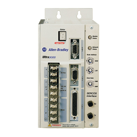
DC bus connections for active shunt resistor kit AC input power connections Motor power connections Motor power cable shield clamp CN3 9-pin serial port connector CN2 15-pin motor feedback connector CN1 44-pin user I/O connector Rockwell Automation Publication 2198-RM003B-EN-P - November 2020... - Page 44 DC Bus Connections for Active Shunt CN2 15-pin Motor Feedback Connector Resistor Kit Logic Power Status Indicator Data Rate Switch Seven Segment Status LED DeviceNet interface connector Module Status Indicator CN1 44-pin User I/O Connector Rockwell Automation Publication 2198-RM003B-EN-P - November 2020...
- Page 45 Motor power connections Module status indicator Passive shunt resistor connections Network status indicator Seven-segment fault status indicator Node address switches Logic power Data rate switch CN3 9-pin serial port connector DeviceNet interface connector Rockwell Automation Publication 2198-RM003B-EN-P - November 2020...
-
Page 46: Kinetix 5100 Servo Drive Connector Data
• Reserved (P1, P2, and negative DC-bus) connections Ethernet (PORT2) RJ45 connector Motor feedback (MFB) connector Ethernet (PORT1) RJ45 connector Motor power output terminals I/O signal connector Shunt resistor terminals Auxiliary feedback (AUX) connector Rockwell Automation Publication 2198-RM003B-EN-P - November 2020... - Page 47 Figure 17 - Features and Indicators (catalog numbers 2198-E4020-ERS, 2198-E4030-ERS) CHARGE 24V+ 24V– DC– Kinetix 5100 Drive, Bottom View Kinetix 5100 Drive, Top View (2198-E4020-ERS drive is shown) (2198-E4020-ERS drive is shown) Kinetix 5100 Drive, Front View (2198-E4020-ERS drive is shown) Rockwell Automation Publication 2198-RM003B-EN-P - November 2020...
- Page 48 Motor power output terminals Ethernet (PORT1) RJ45 connector Shunt resistor terminals Reserved (P1, P2, and negative DC-bus) not-used I/O signal connector connections Auxiliary feedback (AUX) connector Cooling fans Motor cable ground plate Protective cover Rockwell Automation Publication 2198-RM003B-EN-P - November 2020...
-
Page 49: I/O Connector
Figure 19 - Ultra3000 Drive 44-Pin I/O Connector Pin Assignments Pin 30 Pin 15 Pin 44 Pin 31 Pin 1 Pin 16 Figure 20 - Kinetix 5100 Drive 50 Pin I/O Connector Pin Assignment Rockwell Automation Publication 2198-RM003B-EN-P - November 2020... - Page 50 B+/DIR+/CCW+ Digital Input 7 INPUT7 B-/DIR-/CCW- Digital Input 8 INPUT8 Digital input INPUT10 Digital Output 1 OUTPUT1 External power input of AX+/AX- for single-end operation APWR Digital Output 2 OUTPUT2 Digital output OUTPUT6- Rockwell Automation Publication 2198-RM003B-EN-P - November 2020...
-
Page 51: Motor Feedback Connectors
Encoder 9V Power Output MTR_EPWR9V – – – N/C / Encoder power (+9V) Commutation channel S3 Hall Commutation S3 Input – – – MTR_S3 Positive overtravel limit +LIMIT — – – – – Rockwell Automation Publication 2198-RM003B-EN-P - November 2020... -
Page 52: Auxiliary Feedback
Kinetix 5100 drives Figure 22 - 9-Pin Ultra3000 Drive Auxiliary Feedback Connector Pin Assignments Pin 5 Pin 9 Pin 6 Pin 1 Figure 23 - 10-pin Kinetix 5100 drive Auxiliary Feedback Connector Pin Assignment Rockwell Automation Publication 2198-RM003B-EN-P - November 2020... - Page 53 Encoder Common Auxiliary Encoder CH I+ MTR_EPWR5V Encoder 5V Power Output Auxiliary Encoder CH I- Reserved Reserved — — — Reserved Reserved (1) CN1 Connector on the Ultra3000 drive is a 44-pin connector. Rockwell Automation Publication 2198-RM003B-EN-P - November 2020...
- Page 54 Chapter 3 Connectors and Indicators Notes: Rockwell Automation Publication 2198-RM003B-EN-P - November 2020...
-
Page 55: Ultra3000 Drive (230V) Dimensions
(in.) 2098-DSD-005 72.64 2.86) 2098-DSD-005X 2098-DSD-010 65.02 (2.56) 13.26 (0.52) 32.77 (1.29) 2098-DSD-010X 98.1 (3.89) 2098-DSD-020 2098-DSD-020X 2098-DSD-005-DN 95.5 (3.76) 2098-DSD-005X-DN 2098-DSD-010-DN 87.88 (3.46) 24.64 (0.97) 43.94 (1.73) 2098-DSD-010X-DN 121.54 (4.79)) 2098-DSD-020-DN 2098-DSD-020X-DN Rockwell Automation Publication 2198-RM003B-EN-P - November 2020... - Page 56 91.44 (3.6) 50.8 (2.0) 20.32 (0.8) 243.84 (9.6) 2098-DSD-030-DN 2098-DSD-030X-DN 2098-DSD-075 2098-DSD-075X 138.68 (5.41) 88.9 (3.5) 24.89 (0.96) 247.14 (9.73) 2098-DSD-075-DN 2098-DSD-075X-DN 2098-DSD-150 2098-DSD-150X 188.97 (7.44) 139.7 (5.5) 24.6 (0.97) 241.05 (9.49) 2098-DSD-150-DN 2098-DSD-150X-DN Rockwell Automation Publication 2198-RM003B-EN-P - November 2020...
- Page 57 (14.98) 14.26) (15.43) (1) The x represents the indexing (X) option. The -xx represents the Sercos interface (SE) or DeviceNet interface (DN) option. Sercos interface is not available with the DeviceNet interface option. Rockwell Automation Publication 2198-RM003B-EN-P - November 2020...
-
Page 58: Kinetix 5100 Drive Dimensions
(2.30) 2090-CTFB-MxDD Feedback Cable Cat. No. mm (in.) mm (in.) mm (in.) mm (in.) 2198-E1004-ERS 35.0 (1.37) 178 (7.0) 170 (6.68) 52.0 (2.05) 2198-E1007-ERS 50.0 (2.0) 188 (7.41) 180 (7.10) 47.0 (1.84) 2198-E1015-ERS Rockwell Automation Publication 2198-RM003B-EN-P - November 2020... - Page 59 Expansion Block 2090-K51CK-D15M 25.0 Feedback Connector Kit (0.97) 11.0 (0.43) Flying-lead Feedback Cable Additional clearance below the cable connector/connector kit is necessary to provide the recommended cable bend radius. 2090-CTFB-MxDD Feedback Cable 37.0 (1.50) Rockwell Automation Publication 2198-RM003B-EN-P - November 2020...
- Page 60 2198-E4030-ERS 2198-E2055-ERS 120 (4.72) 37.0 (1.47) 59.0 (2.32) 209 (8.24) 273 (10.75) 2198-E4055-ERS 2198-E2075-ERS 141 (5.55) 225 (8.87) 312 (12.28) 2198-E4075-ERS 16.0 (0.65) 35.0 (1.36) 2198-E2150-ERS 186 (7.32) 281 (11.08) 390 (15.35) 2198-E4150-ERS Rockwell Automation Publication 2198-RM003B-EN-P - November 2020...
-
Page 61: Cables
MPL-A2xxx-V/Ex7xAA MPL-A3xxx-S/Mx7xAA MPL-A4xxx-S/Mx7xAA 50 (164) MPL-A45xxx-S/Mx7xAA Hiperface, absolute high-resolution, multi-turn and single-turn MPL-A5xxx-S/Mx7xAA MPM-Axxxx-S/M MPF-Axxxx-S/M MPS-Axxxx-S/M MPL-A15xxx-Hx7xAA MPL-A2xxx-Hx7xAA Incremental MPL-A3xxx-Hx7xAA MPL-A4xxx-Hx7xAA 30 (98.4) MPL-A45xxx-Hx7xAA TLY-Axxxx-B Tamagawa (17-bit) absolute high-resolution, multi-turn TL-Axxxx-B TLY-Axxxx-H Incremental Rockwell Automation Publication 2198-RM003B-EN-P - November 2020... - Page 62 The current motor power cabling system can be used for the Kinetix MP motors that are supported by both the Kinetix 5100 drives and the Ultra3000 drives. The motor power cables are interchangeable and depend on the actuator used. Rockwell Automation Publication 2198-RM003B-EN-P - November 2020...
- Page 63 Drive-end flying-lead brake wires (1) Threaded DIN connector (motor end) and bayonet connector for 2090-XXNFMP-Sxx cable. See the 2090-Series Motor Power and Feedback Transition Cables in the Kinetix Motion Accessories Technical Data, publication KNX-TD004. Rockwell Automation Publication 2198-RM003B-EN-P - November 2020...
- Page 64 • High-resolution applications (1) Threaded DIN connector (motor end) and bayonet connector for 2090-XXNFMP-Sxx cable. See the 2090-Series Motor Power and Feedback Transition Cables in the Kinetix Motion Accessories Specifications Technical Data, publication KNX-TD004. Rockwell Automation Publication 2198-RM003B-EN-P - November 2020...
- Page 65 Ethernet cable of type CAT5E or CAT6, shielded for connecting drive-to-drive, drive-to-controller, or drive-to-switch must not exceed 100 m (328 ft). For more information, see Guidance for Selecting Cables for EtherNet/IP Networks, publication ENET-WP007. Rockwell Automation Publication 2198-RM003B-EN-P - November 2020...
-
Page 66: Power Wiring
Aux Power Converter (2090-U3CBB-DMxx) Aux +5V Common Cable Shield Single-phase Input Clamp 100...240V AC rms L2/N Terminal To additional Blocks* Ultra3000 drive START* STOP* CR1* * Indicates User-supplied Component 24V DC CR1* CR1* Rockwell Automation Publication 2198-RM003B-EN-P - November 2020... - Page 67 Blocks * To additional CR1 * Ultra3000 drive. * Indicates User-supplied Component Figure 34 is the power wiring diagram with 24V DC control string for 2098-DSD-075 - and 2098-DSD-150 - Ultra3000 drives (non-Sercos). Rockwell Automation Publication 2198-RM003B-EN-P - November 2020...
- Page 68 CR1 * M1 * CR1 * Terminal Blocks * To additional * Indicates User-supplied Component Ultra3000 drive Figure 35 is the power wiring diagram with 24V DC control string for the 2098-DSD-HV drives. Rockwell Automation Publication 2198-RM003B-EN-P - November 2020...
- Page 69 You must wait until the Charge light is off. • Separate L1, L2, L3, L1C, L2C, and U, V, W from other wires. The interval should be at least 30 cm (11.8 in.). Rockwell Automation Publication 2198-RM003B-EN-P - November 2020...
- Page 70 253V AC rms. This means that the power system must use center-grounded wye secondary configuration for 230V AC mains. Rockwell Automation Publication 2198-RM003B-EN-P - November 2020...
- Page 71 2198-E1004-ERS, 2198-E1007-ERS, 2198- E1015-ERS, and 2198-E1020-ERS Drives with Single-phase Operation Bonded Cabinet Ground Bus Ground Grid or Power Distribution Ground Reducing the transformer output reduces motor speed. Feeder and branch short-circuit protection is not illustrated. Rockwell Automation Publication 2198-RM003B-EN-P - November 2020...
- Page 72 Mains AC Input Power AC Line Filter 230V AC Connector Output Circuit L1 (Neutral) Protection 2198-E1004-ERS, 2198-E1007-ERS, 2198- E1015-ERS, and 2198-E1020-ERS Drives with Single-phase Operation Bonded Cabinet Ground Bus Ground Grid or Power Distribution Ground Rockwell Automation Publication 2198-RM003B-EN-P - November 2020...
- Page 73 Rotary Servo Motors Kinetix MP Compatible rotary motors include Kinetix MPL, MPM, MPF, and MPS (200V and 400V-class) servo motors. Kinetix TL and TLY Compatible rotary motors include Kinetix TL and TLY (200V-class) servo motors. Rockwell Automation Publication 2198-RM003B-EN-P - November 2020...
- Page 74 (45º) on the drive end and straight connectors that connect to Cables servo motors. Sercos fiber-optic cables are available in enclosure only, PVC, nylon, and glass with Fiber-optic cables connectors at both ends. Rockwell Automation Publication 2198-RM003B-EN-P - November 2020...
- Page 75 (ControlLogix is shown) Software Other compatible motors/actuators include: Motor Power • MP-Series Integrated Linear Stages • MP-Series Electric Cylinders MP-Series and TL-Series Rotary Motors • LDC-Series and LDL-Series Linear Motors (MPL-A xxxx motors shown) Rockwell Automation Publication 2198-RM003B-EN-P - November 2020...
- Page 76 Chapter 5 System Architecture Figure 42 - Ultra3000 Servo Drive System Architecture (DeviceNet Interface) Figure 43 - Ultra3000 Servo Drive System Architecture (Analog or Indexing) Rockwell Automation Publication 2198-RM003B-EN-P - November 2020...
-
Page 77: Kinetix 5100 Drive System Architecture
GuardLogix® 5570 Safety Controllers FORCE SD ControlLogix 5580 Controllers or GuardLogix 5580 Safety Controllers CompactLogix 5370 Controllers or Compact GuardLogix 5370 Safety Controllers CompactLogix 5380 and 5480 Controllers or Compact GuardLogix 5380 Safety Controllers Rockwell Automation Publication 2198-RM003B-EN-P - November 2020... - Page 78 Mini-USB Interface Cable Controller Options with (with 2198-USBF filter) Explicit Messaging Capability 1585J-M8CBJM-x (shielded) or 5100 1585J-M8UBJM-x (high-flex shielded) CHARGE Ethernet Cable To Other EtherNet/IP Devices DC– Kinetix 5100 Servo Drive (2198-E1020-ERS drive is shown) Rockwell Automation Publication 2198-RM003B-EN-P - November 2020...
- Page 79 Kinetix 5100 drives 2198-USBC Mini-USB Interface Cable (with 2198-USBF filter) I/O wiring and Controller Options with Pulse Train Output, Analog, or Digital I/O (indexing) 5100 CHARGE DC– Kinetix 5100 Servo Drive (2198-E1020-ERS drive is shown) Rockwell Automation Publication 2198-RM003B-EN-P - November 2020...
- Page 80 Chapter 5 System Architecture Notes: Rockwell Automation Publication 2198-RM003B-EN-P - November 2020...
- Page 81 For information on how to use KNX5100C software, see the Kinetix 5100 User Manual, publication 2198-UM004. The following examples show the Ultraware software interface followed by the KNX5100C software interface and describe the differences between how they are used to configure the feature. Rockwell Automation Publication 2198-RM003B-EN-P - November 2020...
-
Page 82: Scenario 1: Analog Command To Analog Command
Analog Command, the drive operation mode must be set at T (analog torque), S (analog speed), or PT (analog position) mode (command source ID167 set as Analog Input) respectively. Figure 48 - Analog I/O Window in KNX5100C Software Rockwell Automation Publication 2198-RM003B-EN-P - November 2020... - Page 83 Figure 49 - Monitoring Output Window of Analog I/O in KNX5100C Software Ultraware software can execute commands that remove Velocity, Current, and Position Input Offsets for an online drive. KNX5100C software does not support this feature. Rockwell Automation Publication 2198-RM003B-EN-P - November 2020...
-
Page 84: Scenario 2: Indexing To Pr Mode
Figure 50 - Indexing Branch of Indexing Mode in Ultraware In Ultraware software, you can configure up to 64 indexes. The Ultra3000 drives can support move types including: • Absolute • Incremental • • Registration Rockwell Automation Publication 2198-RM003B-EN-P - November 2020... - Page 85 When using I/O mode, the Add-On Instructions are used to initiate PR commands. See the Kinetix 5100 EtherNet/IP Indexing Servo Drives Users Manual, publication 2198-UM004 for more details on homing and the use of the PR command. Rockwell Automation Publication 2198-RM003B-EN-P - November 2020...
-
Page 86: Scenario 3: Master/Follower Mode To Pt Mode
53. The Kinetix 5100 servo drive provides four selectable gear ratios that can be switched by using digital inputs. For details, see the Kinetix 5100 EtherNet/IP Indexing Servo Drives Users Manual, publication 2198-UM004. Rockwell Automation Publication 2198-RM003B-EN-P - November 2020... - Page 87 Chapter 6 Application Conversion PT command configuration mode in KNX5100C software is shown in Figure Figure 53 - PT Mode Window in KNX5100C Software Rockwell Automation Publication 2198-RM003B-EN-P - November 2020...
-
Page 88: Scenario 4: Devicenet To
(position, velocity, torque, and indexing). Additionally, pre- defined Add-On Instructions are provided to emulate Logix 5000 controller motion instructions for application programming. The configuration and Add-On Instruction example are shown in Figure 55 Figure Rockwell Automation Publication 2198-RM003B-EN-P - November 2020... - Page 89 Figure 55 - Kinetix 5100 Drive in RSLinx Classic Software Figure 56 - Kinetix 5100 Drive Add-On Instruction Logic Used in the Logix Designer Application Rockwell Automation Add-On Instruction Program your project. Kinetix 5100 Choose your Ethernet Communication Module Rockwell Automation Publication 2198-RM003B-EN-P - November 2020...
-
Page 90: Scenario 5: Host Command To Explicit Messaging
‘Set Attribute Single (16), Class 15, Instance 400, Attribute 1, UDINT Value (3000, unit is 0.1 RPM)’. • Set PR Command2 Setting (for example, positioning control) by explicit message ‘Set Attribute Single (16), Class 15, Instance 401, Attribute 1, UDINT Value (0x00000002)’. Rockwell Automation Publication 2198-RM003B-EN-P - November 2020... - Page 91 • Stop the PR Command by explicit message ‘Set Attribute Single (16), Class 15, Instance 300, Attribute 1, UINT Value (1000)’. • Get the status of PR Command by explicit message ‘Get Attribute Single (14), Class 15, Instance 300, Attribute 1’. Rockwell Automation Publication 2198-RM003B-EN-P - November 2020...
- Page 92 Chapter 6 Application Conversion Notes: Rockwell Automation Publication 2198-RM003B-EN-P - November 2020...
- Page 93 * Kinetix MP Motor, TLP Motor, TL and TLY Multiple Motors Supported Yes* Motor Dual-port Ethernet with DLR support — Non-Integrated Motion Drive (Ethernet/IP Standalone) — Drive configuration software required Ability to home the drive — Rockwell Automation Publication 2198-RM003B-EN-P - November 2020...
- Page 94 Yes* * Not natively, programming required Batch Count Yes* * Not natively, programming required Homing, Active/Switch/Marker — Homing, Absolute — Home to Torque Limit — Define Home current position — Stop Indexing — Rockwell Automation Publication 2198-RM003B-EN-P - November 2020...
- Page 95 Ultra3000 to Kinetix 5100 Servo Drives Migration Guide Reference Manual Notes: Rockwell Automation Publication 2198-RM003B-EN-P - November 2020...
- Page 96 Allen-Bradley, CompactLogix, Connected Components Workbench, ControlLogix, expanding human possibility, FactoryTalk, GuardLogix, Integrated Architecture Builder, Kinetix, Logix 5000, Logix PAC, Micro800, Micro830, MicroLogix, ProposalWorks, Rockwell Automation, RSLinx, RSLogix 500, RSLogix 500, RSNetWorx, SLC, Stratix, Studio 5000, Studio 5000 Logix Designer, and Ultra3000 are trademarks of Rockwell Automation, Inc.
Need help?
Do you have a question about the Allen-Bradley Ultra3000 and is the answer not in the manual?
Questions and answers