Sign In
Upload
Manuals
Brands
Rockwell Automation Manuals
Servo Drives
Allen-Bradley 2198-E2075-ERS
Rockwell Automation Allen-Bradley 2198-E2075-ERS Manuals
Manuals and User Guides for Rockwell Automation Allen-Bradley 2198-E2075-ERS. We have
4
Rockwell Automation Allen-Bradley 2198-E2075-ERS manuals available for free PDF download: User Manual, Migration Manual
Rockwell Automation Allen-Bradley 2198-E2075-ERS User Manual (556 pages)
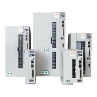
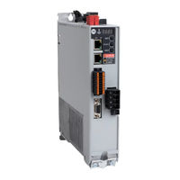
EtherNet/IP Indexing Servo Drives
Brand:
Rockwell Automation
| Category:
Servo Drives
| Size: 43.47 MB
Table of Contents
Table of Contents
3
Preface
13
Summary of Changes
13
Conventions
13
Access Fault Codes and Parameter List
13
Additional Resources
14
Start
17
About the Kinetix 5100 Drive System
17
Typical Hardware Configuration
19
Motor and Auxiliary Feedback Configurations
20
Typical Communication Configurations
21
Linear Topology
21
Ring Topology
22
Star Topology
23
Typical Control Configurations
24
Logix Enabled Using a Class 1 Ethernet/Ip Connection
25
Micro800 Using a Class 3 Ethernet/Ip Connection
26
Pulse Train Output Control with Motion User Defined Function Block
27
Catalog Number Explanation
28
Agency Compliance
29
Plan and Install the Kinetix 5100 Drive System
31
System Design Guidelines
31
System Mounting Requirements
31
AC Line Filter Selection
32
Circuit Breaker/Fuse Selection
33
Transformer Selection
35
Passive Shunt Considerations
35
Enclosure Selection
36
Minimum Clearance Requirements
38
Electrical Noise Reduction
40
HF Bond the Drives
40
HF Bond Multiple Subpanels
42
Establish Noise Zones
43
Cable Categories for Kinetix 5100 Drive Systems
44
Noise Reduction Guidelines for Drive Accessories
44
Mount Your Kinetix 5100 Drive
47
Drill-Hole Patterns
47
Mount the Drive
48
Connector Data and Feature Descriptions
50
Kinetix 5100 Connector Data
50
Safe Torque-Off Connector Pinout
52
Power Connector Pinouts
53
Auxiliary Feedback Connector Pinout
56
Ethernet Communication Connector Pinout
57
Control Signal Specifications
57
Digital Inputs
57
Digital Outputs
60
Analog Inputs
63
Pulse Inputs
63
Analog Outputs
65
Buffered Encoder Outputs
65
Ethernet Communication Specifications
67
Motor Brake Circuit
68
Control Power
71
Feedback Specifications
72
Motor Feedback Supported by Using the MFB Connector
73
Auxiliary Feedback Specifications
74
Encoder Phasing Definitions
75
Absolute Position Feature
76
Safe Torque off Feature
77
Operation Modes
77
Connect the Kinetix 5100 Drive System
79
Basic Wiring Requirements
79
Build Your Own Cables
80
Route Power and Signal Wiring
80
Determine the Input Power Configuration
80
Three-Phase Power Wired to Three-Phase Drives
81
Single-Phase Input Power Used with Single-Phase Drives
82
Three-Phase Input Power Used with Single-Phase Drives
83
Voiding of CE and UK Compliance
84
Using Isolation Transformers with Grounded Power Configurations
84
Ground the Drive System
85
Ground Your Drive to the System Subpanel
85
Ground Multiple Subpanels
86
Wiring Requirements
86
Wiring Guidelines
88
Wire the Input Power Connectors
89
Wire the I/O Connector
91
Wire the Safe Torque off Connector
91
Wire the Motor Power Connector
91
Servo Motor and Motor Cable Compatibility
93
Motor Power and Brake Cables
94
Maximum Cable Length
95
Cable Preparation for Kinetix TLP Servo Motors
96
Cable Preparation for Kinetix MP Servo Motors
97
Cable Preparation for Kinetix TL and TLY Motor Power Cables
98
Apply the Cable Shield Clamp
98
Motor Brake Connections
100
Wire the Motor Feedback Connector
100
Cable Preparation for Kinetix TLP Feedback Cables
101
Cable Preparation for 2090-Cfbm7Dx Feedback Cables
102
Cable Preparation for Kinetix TL and TLY Feedback Cables
102
Motor Feedback Cable Preparation
103
Kinetix 2090 Feedback Cable Pinouts
105
External Passive-Shunt Resistor Connections
108
Ethernet Cable Connections
110
Set up Ethernet/Ip Communication
112
Set Network Parameters by Using the Keypad Interface
112
Set Network Parameters by Using KNX5100C Software
114
Configure IP Address by Using BOOTP-DHCP Tool
115
Use the Keypad Interface
117
Keypad Input and Panel Display
117
Drive Displays
118
Real Time Data
118
Drive Status Display
121
Edit Settings from the Display
122
Edit Network Settings
122
Edit Parameter Settings
124
Reset the Drive Via Keypad
125
Display Low Byte, High Byte, and Negative Values
126
Display Fault Record
127
Diagnosis Parameters Via Keypad
127
Display Firmware Upgrade Information
128
Configure the Drive with KNX5100C Software
129
Before You Begin
129
Download KNX5100C Software
130
Launch KNX5100C Configuration Tool
130
Connect to the Drive/Set Your COM Port
132
Configure Drive Settings
134
Set the IP Address
134
Configure the Motor Selection in KNX5100C Software
134
Data Source
135
Selection of Motor Thermal Models
146
Motor Feedback
148
Run a Commutation Test
150
Parameter Editor
152
Parameter Wizard
154
Parameter Toolbar
154
Choose an Operation Mode
156
Using the Operation Mode Selection List
156
Using the Setting Page
157
Using the Parameter Editor
157
Configure Settings
159
Configure General Settings
160
Configure the Command Source
164
Configure the Pulse Outputs
168
Configure Electronic Gear (E-Gear) Ratio
169
Configure Filter
174
Configure Notch Filter
176
Configure Limits
177
Configure Analog I/O
178
Configure Position, Velocity, and Current Loops
182
Configure Position Loop
182
Configure Velocity Loop
183
Configure Current Loop
184
Digital I/O and Jog Function in KNX5100C Software
184
Configuration and Status of Digital Input (DI) and Digital Output (DO) Signals
185
Edit DIO Configurations
187
Jog Function
188
Configure the Drive in Studio 5000 Logix Designer Application
189
Studio 5000 Logix Designer Application
189
Version History
189
Install the Kinetix 5100 Add-On Profile
190
Configure the Logix 5000 Controller
190
Configure the Kinetix 5100 Drive Modules
194
Support Automatic Device Configuration (ADC) in AOP Version 2 and Later
196
Connection RPI
197
Inhibiting/Un-Inhibiting an I/O Connection
197
Download the Program
198
Tuning
199
Tuning Process
200
Reset Gains to Default
200
Bandwidth
200
Autotuning
203
Autotuning Configuration Parameters
203
Autotuning Via the Drive Panel
204
Autotuning Via KNX5100C Software
206
Alarms Related to Autotuning
211
Tuning Via Tuning Mode 1 and Tuning Mode 2
212
Tuning Mode Process
212
Tuning Mode 1
213
Tuning Mode 2
215
Tuning in Manual Mode
218
Nested P-I Loop Gain Adjustment
218
Manual Mode Tuning
218
Gain Adjustment of the Position Loop
220
Gain Adjustment of Velocity Loop
222
Low Frequency Vibration Suppression in Position Mode
226
Mechanical Resonance Suppression
227
System Analysis
228
Phase Margin and Gain Margin
228
Guidelines for Gain/Phase Margin
229
Method for Using the System Analysis Tool
229
System Analysis Results
231
Modes of Operation
233
Select Operation Mode and Direction Control
234
Change Using the Parameter Editor by Using KNX5100C Software or Programmatically
234
Position Control
236
Mode (Position Command with I/O Terminal Block Input)
237
Pulse Command Input Inhibitor (INHP)
240
Analog Input
240
PR Mode (Position Command with Internal Register Input)
243
Control Structure of Position Mode
244
Position Mode Timing (PR Mode)
245
Speed Mode
246
Configure and Select the Preset Speeds
246
Scaling the Analog Command (Speed Mode)
247
Control Structure of Speed Mode
248
Speed Mode Timing
249
Zero Speed Threshold Function
249
Torque Mode
252
Selection of Torque Command
252
Control Structure of Torque Mode
253
Scaling of Analog Command (Torque Mode)
254
Torque Mode Timing
255
Filter
256
Position Mode
256
Speed Mode
257
Torque Mode Low Pass Filter
262
Speed and Torque Limit Functions
263
Speed Limits
263
Apply a Speed Limit
264
Torque Limits
265
Apply the Torque Limit
267
Enable/Disable Limits by Using Velocitytorquelimitaction
268
Dual and Multi-Modes
269
IO Mode
271
IO Mode - Position
279
IO Mode - Home
279
IO Mode - Gear
280
IO Mode - Index
281
IO Mode - Speed
281
IO Mode - Torque
281
Analog Outputs and Monitoring
282
Motion Control in PR Mode
285
Detailed Operation in PR Mode
286
Parameter Editor
286
PR Mode Definitions
288
Shared PR Parameters
293
Monitoring Variables in PR Mode
294
Homing
298
Setting Homing Mode ID297 (P5.004) - PR Mode
298
Configuring Homing Setting ID397 (P6.000) - PR Mode
299
Homing Speed and Position
300
Operation of Homing Types
300
Constant Speed Control
324
Position Control Command
326
Position Command Types
327
Jump Command
329
Write Command
331
Index Position Command
333
Hex Settings for Index Coordinate System
334
Index Coordinates Settings Wizard
335
Index Position Command Operation
338
Arithmetic Operation Commands
339
Arithmetic Operations
339
Use the PR Mode Editor in KNX5100C Software
342
Speed and Time Settings
343
General Parameter Settings
344
Homing Setting
345
PR Mode Setting
346
Display of PR Procedure in KNX5100C Software
348
Parts of the PR Display
348
Homing PR Display
349
Speed Command PR Display
350
Position Command PR Display
351
Jump Command PR Display
352
Write Command PR Display
352
Index Position Command PR Display
353
Arithmetic Operation PR Display
354
Trigger Methods for PR Commands
354
Digital Input (DI) Trigger
354
Event Trigger
356
Use PR Command Trigger ID300 (P5.007)
357
Use IO Mode and Add-On Instruction
357
PR Execution Process
358
Sequence Command Execution
359
Command Interrupts Execution
363
Overlap Command Execution
369
Arithmetic Operation Command Execution
370
Motion Control Applications
371
High-Speed Position Capture Function (CAP)
371
Using PR Command Programming with the Capture Function
375
High-Speed Position Compare Function (CMP)
378
Data Array
383
E-Cam
384
E-CAM Control Settings
386
Master Axis Signal Source
388
Clutch Engagement and Disengagement
392
E-CAM Alignment
397
E-CAM Profile Types
400
Kinetix 5100 Safe Torque off
409
Certification
410
Important Safety Considerations
410
Category 3 Requirements According to ISO 13849-1
410
Stop Category Definition
410
Performance Level (PL) and Safety Integrity Level (SIL)
410
Description of Operation
411
STO-Related Fault Codes
412
Average Frequency of a Dangerous Failure Per Hour
414
Safe Torque off Connector Data
415
Wire the Safe Torque off Circuit
415
Safe Torque off Wiring Requirements
416
Safe Torque off Feature
416
Safe Torque off Feature Bypass
417
Cascade the Safe Torque off Signal
417
Safe Torque off Specifications
418
Safe Torque off Wiring Diagrams
418
Absolute Position Recovery
423
System Requirements
423
Compatible Servo Motors
423
Install the Battery
425
System Initialization
426
Pulse Number
427
PUU Number
429
Initializing the Absolute Coordinates with Parameters
429
Programming Via Drive Parameters
431
Organization of Parameters
431
Parameter Groups
431
Description of Digital Input Functions
433
Description of Digital Output Functions
437
Description of System Variable Monitoring
440
Panel Display
440
System Variable Monitoring Parameters
440
System Variables List
441
Description of Parameter Monitoring
445
Use a MSG Instruction to Set Parameters
447
Troubleshoot the Kinetix 5100 Drive System
449
Safety Precautions
449
Status Indicators
449
View Status and Faults
450
Drive Fault Code Display
450
Monitoring Status in KNX5100C Software
451
Fault Information in the KNX5100C Software
452
Fault and Status Information in Studio 5000 Application
453
Drive Stopping Behavior
454
Clear Faults
454
General Troubleshooting
455
Interconnect Diagrams
457
Interconnect Diagram Notes
457
Power Wiring Examples
458
Passive Shunt Wiring Examples
463
Kinetix 5100 Drive/Rotary Motor Wiring Examples
464
Kinetix 5100 Servo Drive and Linear Actuator Wiring Examples
470
System Block Diagram
475
Upgrade Kinetix 5100 Drive Firmware
477
Before You Begin
477
Inhibit the Module
478
Upgrade Your Firmware
479
Use Controlflash Plus Software to Upgrade Your Drive Firmware
479
Use Controlflash Software to Upgrade Your Drive Firmware
482
Verify the Firmware Upgrade
487
Use Add-On Instructions
489
Use of the Add-On Instruction Library
489
Kinetix 5100 Drive Device Object Add-On Instructions
490
Download the Add-On Instruction Files and Data Types
492
Import the Add-On Instruction Files and Data Types (Version 1.XXX)
492
DVC Add-On Instruction Configuration (Version 1.XXX)
494
Create the Add-On Instruction Tag
494
Create the Ref_Axis Tag
495
Configure the Add-On Instruction
496
General Execution Rules for Add-On Instructions
496
Opr Add-On Instruction Configuration
497
Rac_Udt_Itf_K5100_Cfg
497
Rac_Udt_Itf_K5100_Set
498
Rac_Udt_Itf_K5100_Cmd
500
Rac_Udt_Itf_K5100_Sts
501
Rac_Udt_Lookupmember_Str0082
502
Rac_Udt_Event
503
Add-On Instruction Details
504
Rac_Xxx_K5100_Mso
504
Rac_Xxx_K5100_Msf
505
Rac_Xxx_K5100_Mafr
506
Rac_Xxx_K5100_Mas
508
Rac_Xxx_K5100_Maj
509
Rac_Xxx_K5100_Mam
511
Rac_Xxx_K5100_Mai
515
Rac_Xxx_K5100_Mag
517
Rac_Xxx_K5100_Mah
520
Rac_Xxx_K5100_Mat
522
Error Codes
524
Full Closed-Loop Control
526
Use the Scope Function in KNX5100C Software
529
Get Started
529
Scope Functions
530
Quick Setup of Communication Channels
530
Select Communication Channels
531
Enable Stop Condition
534
FFT Display and Show RMS Value
535
Fine-Tune the Scope
536
Set Preferences
537
Use Popup Menu for Save Options
538
Automatic Device Configuration
539
New Kinetix Drive ADC Preparation
539
Get Started
541
Compare the Configuration Data
542
Upload the Configuration Data
543
Overwrite the Configuration Data
544
History of Changes
545
Index
547
Advertisement
Rockwell Automation Allen-Bradley 2198-E2075-ERS Migration Manual (75 pages)
Servo Drive Migration Guide
Brand:
Rockwell Automation
| Category:
DC Drives
| Size: 8.09 MB
Table of Contents
Table of Contents
3
Download Firmware, AOP, EDS, and Other Files
5
Preface
5
Summary of Changes
5
Migration Options
7
Kinetix 5100 Servo Drive Catalog Numbers
8
Replacement Considerations
11
Selecting a Replacement Drive
11
Drive Sizing
12
Nominal Voltage and Output Current Comparison
12
AC Input Power Configuration
13
AC Input Power Wiring and Fusing
13
Dimension Comparison
13
Input Power Wiring and Fusing
13
Circuit Breaker and Fuse Considerations
14
Power Specifications
15
Digital Inputs
20
I/O Availability and Specifications
20
Digital Outputs
23
Analog Inputs
25
Analog Outputs
26
Control and Auxiliary Power Specifications
28
Compatible Motors
29
Accessories
30
Feedback Devices
30
Required Accessories
30
Optional Drive Accessories - Shunt Resistors
31
Optional Drive Accessories - AC Line Filters
33
Communication
34
Kinetix 300 Servo Drive Configuration Port
34
Kinetix 300 Servo Drive Control Port
35
Kinetix 5100 Servo Drive Configuration Port
35
Kinetix 5100 Servo Drive Control Port
35
Programming Software
35
Connectors
37
Kinetix 300 Servo Drive Connector Locations
37
Kinetix 5100 Servo Drive Connector Locations
38
I/O Connector Pinouts
40
Motor Feedback
42
Auxiliary Feedback
43
Safe Torque off Connector
44
Dimension Drawings
45
Kinetix 5100 Drive Dimensions
46
Cables
49
Motor and Feedback Cables
49
Power Wiring
50
Replacement Considerations
50
Kinetix 300 Servo Drive Power Wiring Examples
51
Kinetix 5100 Servo Drives Power Wiring Examples
53
Kinetix 300 Servo Drive System Architecture
59
Instruction
60
Kinetix 5100 Servo Drive System Architecture
60
Kinetix 5100 Drive Controlled Via Explicit Messaging
61
Analog/ Digital I/O
62
Scenario 1: Analog Command to Analog Command
64
Scenario 2: Indexing to Position Register (PR) Mode
65
Scenario 3: Master / Gearing Mode to PT Mode
68
Scenario 4: Ethernet/Ip External Reference to I/O Mode
70
Appendix A Feature Comparison
71
Appendix B History of Changes
73
Rockwell Automation Allen-Bradley 2198-E2075-ERS Migration Manual (96 pages)
Brand:
Rockwell Automation
| Category:
Servo Drives
| Size: 9.1 MB
Table of Contents
Table of Contents
3
Preface
5
Summary of Changes
5
Overview
6
Integrated Architecture Builder Software
6
Motion Analyzer Software
6
Migration Services
6
Additional Resources
7
Kinetix 5100 Servo Drive Catalog Numbers
10
Drive Sizing
14
AC Input Power Wiring and Fusing
17
Power Specifications
19
I/O Availability and Specifications
26
Feedback Devices
35
Accessories
35
Communication
40
Ultra3000 Servo Drive Connector Data
43
Kinetix 5100 Servo Drive Connector Data
46
I/O Connector
49
Motor Feedback Connectors
51
Auxiliary Feedback
52
Ultra3000 Drive (230V) Dimensions
55
Kinetix 5100 Drive Dimensions
58
Cables
61
Power Wiring
66
Kinetix 5100 Drive System Architecture
77
Scenario 1: Analog Command to Analog Command
82
Scenario 2: Indexing to PR Mode
84
Scenario 3: Master/Follower Mode to PT Mode
86
Scenario 4: Devicenet to
88
I/O Mode
88
Scenario 5: Host Command to Explicit Messaging
90
Advertisement
Rockwell Automation Allen-Bradley 2198-E2075-ERS Migration Manual (70 pages)
Brand:
Rockwell Automation
| Category:
Servo Drives
| Size: 4.98 MB
Table of Contents
Table of Contents
3
Additional Resources
5
Preface
5
Migration Options
7
Chapter 1 Kinetix 5100 Servo Drive Catalog Numbers
8
Potential Design Changes
8
Replacement Considerations
11
Chapter 2 Selecting a Replacement Drive
12
Drive Sizing
12
Nominal Voltage and Output Current Comparison
12
Dimension Comparison
13
AC Input Power Wiring and Fusing
14
AC Input Power Configuration
14
Input Power Wiring and Fusing
14
Circuit Breaker and Fuse Considerations
15
Power Specifications
16
I/O Availability and Specifications
18
Digital Inputs
19
Digital Outputs
22
Analog Inputs
24
Analog Outputs
25
Control and Auxiliary Power Specifications
27
Motors
28
Feedback Devices
28
Accessories
28
Required Accessories
29
Optional Drive Accessories - Shunt Resistors
29
Optional Drive Accessories - AC Line Filters
32
Communication
33
Port for Configuration
33
Port for Control
33
Chapter 3 Kinetix 300 Servo Drive Connector Locations
35
Kinetix 5100 Servo Drive Connector Locations
36
I/O Connector Pinouts
38
Motor Feedback
40
Auxiliary Feedback
41
Safe Torque off Connector
42
Connectors
35
Chapter 4 Dimension Drawings
43
Kinetix 5100 Drive Dimensions
44
Cables
47
Motor and Feedback Cables
47
Power Wiring
48
Kinetix 300 Servo Drive Power Wiring Examples
48
Kinetix 5100 Servo Drives Power Wiring Examples
49
Dimensions, Cables, and Wiring
43
Chapter 5 Kinetix 300 Servo Drive System Architecture
55
Kinetix 5100 Servo Drive System Architecture
56
Chapter 6 Scenario 1: Analog Command to Analog Command
59
Scenario 2: Indexing to PR Mode
61
Scenario 3: Master / Gearing Mode to PT Mode
63
Scenario 4: Ethernet/Ip External Reference to I/O Mode
66
Advertisement
Related Products
Rockwell Automation Allen-Bradley 2198-E2030-ERS
Rockwell Automation Allen-Bradley 2198-E2055-ERS
Rockwell Automation Allen-Bradley 2198-E2150-ERS
Rockwell Automation Allen-Bradley 2198-E1004-ERS
Rockwell Automation Allen-Bradley 2198-E1007-ERS
Rockwell Automation Allen-Bradley 2198-E1015-ERS
Rockwell Automation Allen-Bradley 2198-E1020-ERS
Rockwell Automation 2198-C4007-ERS
Rockwell Automation 2198-C4030-ERS
Rockwell Automation 2198-C4015-ERS
Rockwell Automation Categories
Controller
Control Unit
Power Supply
DC Drives
Industrial Equipment
More Rockwell Automation Manuals
Login
Sign In
OR
Sign in with Facebook
Sign in with Google
Upload manual
Upload from disk
Upload from URL