Rockwell Automation Allen-Bradley Ultra3000 Migration Manual
Hide thumbs
Also See for Allen-Bradley Ultra3000:
- Manual (80 pages) ,
- Migration manual (96 pages) ,
- Integration manual (180 pages)
Table of Contents

Related Manuals for Rockwell Automation Allen-Bradley Ultra3000


Summary of Contents for Rockwell Automation Allen-Bradley Ultra3000
- Page 1 Reference Manual Original Instructions Ultra3000 to Kinetix 5100 Servo Drives Migration Guide Catalog Numbers 2198-E1004-ERS, 2198-E1007-ERS, 2198-E1015-ERS, 2198-E1020-ERS, 2198-E2030-ERS, 2198-E2055-ERS, 2198-E2075-ERS, 2198-E2150-ERS...
- Page 2 If this equipment is used in a manner not specified by the manufacturer, the protection provided by the equipment may be impaired. In no event will Rockwell Automation®, Inc. be responsible or liable for indirect or consequential damages resulting from the use or application of this equipment.
-
Page 3: Table Of Contents
Ultra3000 Servo Drive Connector Data......41 Connectors and Indicators Rockwell Automation Publication 2198-RM003A-EN-P - February 2020... - Page 4 Scenario 4: DeviceNet to I/O Mode ......82 Scenario 5: Host Command to Explicit Messaging ....83 Appendix A Feature Comparison Rockwell Automation Publication 2198-RM003A-EN-P - February 2020...
-
Page 5: Preface
Kinetix motion control system. This online tool facilitates the machine design process, and lets you quickly design and validate new machine concepts without purchasing or installing physical equipment. Rockwell Automation Publication 2198-RM003A-EN-P - February 2020... -
Page 6: Migration Services
Whether you choose to migrate all at once or use our unique, phased approach to help minimize the costs, risks, and complexities that are involved with the management of legacy products and systems, Rockwell Automation has the tools and the experience to guide you through the transition. - Page 7 Manual, publication GMC-RM001. (HF) bonding, the Ground Plane principle, and electrical noise reduction. Product Certifications website: rok.auto/certifications Provides declarations of conformity, certificates, and other certification details. You can view or download publications at http://www.rockwellautomation.com/global/literature-library/overview.page. Rockwell Automation Publication 2198-RM003A-EN-P - February 2020...
- Page 8 Preface Notes: Rockwell Automation Publication 2198-RM003A-EN-P - February 2020...
-
Page 9: Migration Options
S or Sz mode, or PR mode Preset Position PR mode Follower PT mode Indexing PR mode Host Command Any mode with Explicit Messaging over EtherNet/IP DeviceNet IO mode (with Logix Add-On Instructions) using the EtherNet/IP network Rockwell Automation Publication 2198-RM003A-EN-P - February 2020... -
Page 10: Kinetix 5100 Servo Drive Catalog Numbers
1 PH 13.4 53.03 170…253V 1 PH,3 PH 2198-E2030-ERS 170…253V 3 PH – 17.9 55.95 2198-E2055-ERS 170…253V 3 PH – 41.3 91.4 2198-E2075-ERS 170…253V 3 PH – 127.49 2198-E2150-ERS 170…253V 3 PH – Rockwell Automation Publication 2198-RM003A-EN-P - February 2020... -
Page 11: Potential Design Changes
5…55 Hz @ 0.35 mm (0.014 in.) double max displacement amplitude, continuous displacement 55…500 Hz @ 2.0 g peak constant acceleration Shock 15 g, 11 ms half-sine pulse 15 g, 11 ms half-sine pulse Rockwell Automation Publication 2198-RM003A-EN-P - February 2020... - Page 12 — WEEE (1) When product is marked, see rok.auto/certifications for Declarations of Conformity Certificates. (2) UL has not evaluated the safe-off, Safe Torque Off, or safe speed-monitoring options in these products. Rockwell Automation Publication 2198-RM003A-EN-P - February 2020...
-
Page 13: Replacement Considerations
In no event will Rockwell Automation be responsible or liable for indirect or consequential damage resulting from the use or application of these products. -
Page 14: Selecting A Replacement Drive
Most Ultra3000 drives can be replaced with a Kinetix 5100 drive of similar, or in some cases greater, output current capability. The Kinetix 5100 drives require less physical space than the Ultra3000 drives. Rockwell Automation Publication 2198-RM003A-EN-P - February 2020... -
Page 15: Nominal Voltage And Output Current Comparison
230V 3 PH 41.3 (58.40) 91.4 (129.24) 3 PH 3 PH 2098-DSD-150 88…265V 120…240V 45.9 (65) 106.0 (150) 2198-E2075-ERS 170…253V 3 PH 230V 3 PH 49.0 (69.3) 78.0 (110.3) 3 PH 3 PH Rockwell Automation Publication 2198-RM003A-EN-P - February 2020... -
Page 16: Dimension Comparison
In general, the recommended drive replacement should not require changes in wiring length; however, the routing may need to change as the input power and motor power connections could be in different physical locations with different terminations. Rockwell Automation Publication 2198-RM003A-EN-P - February 2020... -
Page 17: Circuit Breaker And Fuse Considerations
Evaluation of the short circuit available current is critical and must be kept below the short-circuit current rating of the circuit breaker. Rockwell Automation Publication 2198-RM003A-EN-P - February 2020... - Page 18 230V, 3 PH LPJ-50SP 1489-M3D350 60 A 1489-M3D350 2198-E2055-ERS 230V, 3 PH LPJ-70SP 1489-M3D600 110 A 1489-M3D600 2198-E2075-ERS 230V, 3 PH LPJ-80SP 140G-G2C3-C70 150 A 140G-G2C3-C70 2198-E2150-ERS 230V, 3 PH LPJ-125SP 140G-G2C3-D12 225 A 140G-G2C3-D12 Rockwell Automation Publication 2198-RM003A-EN-P - February 2020...
-
Page 19: Power Specifications
(3) Power initialization requires a short period of inrush current. Dual element time delay (slow blow) fuses are recommended. (4) Inrush current limiting circuitry is enabled within 3 s after removal of AC line power. Rockwell Automation Publication 2198-RM003A-EN-P - February 2020... - Page 20 Short-circuit current rating 5000 A (rms) symmetrical (1) Kinetix 5100 drive modules are limited to one AC mains power cycles per minute. (2) Peak RMS current that is allowed for up to 1.8 seconds. Rockwell Automation Publication 2198-RM003A-EN-P - February 2020...
- Page 21 Short-circuit current rating 5000 A (rms) symmetrical (1) Kinetix 5100 drive modules are limited to one AC mains power cycling per minute. (2) Peak RMS current that is allowed for up to 1.8 seconds. Rockwell Automation Publication 2198-RM003A-EN-P - February 2020...
-
Page 22: I/O Availability And Specifications
Current flow to guarantee an ON State 3.0 mA 12.0 mA 2.0 mA 6.0 mA OFF state voltage Voltage applied to the input, with respect -1.0V 2.0V -1.0V 5.0V IOCOM, to guarantee an OFF state Rockwell Automation Publication 2198-RM003A-EN-P - February 2020... -
Page 23: Functionality Inputs
Kinetix 5100 drives is shown in the second column of Table 18. There is not a direct correlation with the functionality for the Ultra3000 drive - they are shown side by side for convenience. Rockwell Automation Publication 2198-RM003A-EN-P - February 2020... - Page 24 12-24V DC digital inputs. The Kinetix 5100 drives, which are shown in Figure 2, the digital inputs are optically isolated and sink up to 24V DC. You can design the inputs for PNP sourcing or NPN sinking. Rockwell Automation Publication 2198-RM003A-EN-P - February 2020...
-
Page 25: Digital Outputs
The Kinetix 5100 drive requires an external relay. See the Kinetix 5100 Single-axis EtherNet/IP Servo Drives User Manual, publication 2198-UM004 for more information on how to configure and use the holding brake. Rockwell Automation Publication 2198-RM003A-EN-P - February 2020... - Page 26 The Kinetix 5100 drive has default assignments for the digital outputs. Figure 3 - Ultra3000 Digital Output Circuit 200 Ω IOPWR OUTPUT TLP127 Rockwell Automation Publication 2198-RM003A-EN-P - February 2020...
- Page 27 Within Position Target position reached Within Position Target position reached Window (TPOS) Window (TPOS) Output5 ALRM Servo alarm ALRM Servo alarm Output6 — — — — (1) Position error smaller than ID159 (P1.054) setting. Rockwell Automation Publication 2198-RM003A-EN-P - February 2020...
-
Page 28: Analog Inputs
Figure 5 - Ultra3000 Analog Input Circuit Ultra3000 Drive 1000 μF 10k W 10k W 20k W COMMAND + 0.01 mF 10k W 10k W COMMAND - 0.01 mF 1000 μF 20k W Rockwell Automation Publication 2198-RM003A-EN-P - February 2020... -
Page 29: Analog Output
50 Hz 50 Hz min The Ultra3000 uses one programmable analog output. The Kinetix 5100 servo drive provides two programmable analog outputs (MON1 and MON2) which are single-ended based on the analog ground. Rockwell Automation Publication 2198-RM003A-EN-P - February 2020... - Page 30 / 450V) Velocity Command P1.101 Preset Analog Output Value 1 Velocity Error P1.102 Preset Analog Output Value 2 Velocity Feedback — — (1) ID 103 (P0.003) (2) +/-8V or +/-10V depending on configuration Rockwell Automation Publication 2198-RM003A-EN-P - February 2020...
-
Page 31: Control And Auxiliary Power Specifications
18.20 0.22 37.40 2198-E1015-ERS 0.38 19.20 0.22 39.80 2198-E1020-ERS 0.63 19.20 0.35 32.40 2198-E2030-ERS — — 0.35 36.40 2198-E2055-ERS — — 0.46 32.80 2198-E2075-ERS — — 0.48 40.00 2198-E2150-ERS — — 0.92 37.00 Rockwell Automation Publication 2198-RM003A-EN-P - February 2020... -
Page 32: Motors
(RBM), and external auxiliary encoder are not shared with Kinetix 5100 servo drives. Application accessories such as shunts and line filters, can impact drive replacement, so they are covered in this section. Rockwell Automation Publication 2198-RM003A-EN-P - February 2020... -
Page 33: Required Drive Accessories
Optional Drive Accessories - Ethernet Cable A 1585J series Ethernet cable(1585J-M8CBJM- , 1585J-M8UBJM- , 1585J-M8CB- ) is required when a Kinetix 5100 drive is controlled via Ethernet (either in IO mode or via Explicit Messaging). Rockwell Automation Publication 2198-RM003A-EN-P - February 2020... -
Page 34: Optional Drive Accessories - Shunt Resistors
Catalog numbers 2198-R004, 2097-R6, and 2097-R7are shunt resistors without an enclosure. Figure Figure Figure Table 34, and Table 35 describe the shunt resistor specification and dimensions. Rockwell Automation Publication 2198-RM003A-EN-P - February 2020... - Page 35 Figure 10 - Product Dimensions: Catalog Number 2198-R004 in mm (in.) 305 (12.0) 292 (11.5) Top View 38.1 (1.5) Ø (2) 457 mm (18 in.) 450 °C (842 °F) 5.6 (7/32) Mounting Holes High-Temperature Wire Leads Side View 76.2 (3.0) Rockwell Automation Publication 2198-RM003A-EN-P - February 2020...
-
Page 36: Optional Drive Accessories - Ac Line Filters
Kinetix 5100 drive for your application, choose the line filter that is appropriate for that particular drive. This section describes the specifications for the line filters used for each drive. Rockwell Automation Publication 2198-RM003A-EN-P - February 2020... - Page 37 Cat. No. (single-phase operation) (three-phase operation) 2198-E1004-ERS 2198-DB111-F 2198-DB310-F 2198-E1007-ERS 2198-E1015-ERS 2198-DB127-F 2198-E1020-ERS 2198-DB324-F 2198-E2030-ERS — 2198-E2055-ERS — 2198-DB335-F 2198-E2075-ERS — 2198-DB356-F 2198-E2150-ERS — 2198-DBR90-F (1) 2198-E2xxx-ERS servo drives do not support single-phase operation. Rockwell Automation Publication 2198-RM003A-EN-P - February 2020...
-
Page 38: Communication
The Ultra3000 servo drives use MODBUS communication over RS232/RS422/ RS485 or DeviceNet for controlling the drive. A DeviceNet interface module serves as a link between the ControlLogix/CompactLogix platform and the Ultra3000 servo drive system. Rockwell Automation Publication 2198-RM003A-EN-P - February 2020... -
Page 39: Kinetix 5100 Servo Drive Control Port
RSLogix 500® software(for MicroLogix controllers) is required to program the controller for controlling the Kinetix 5100 drives. For information on how to use these programs, see the corresponding controller user manuals. Rockwell Automation Publication 2198-RM003A-EN-P - February 2020... - Page 40 Chapter 2 Replacement Considerations Notes: Rockwell Automation Publication 2198-RM003A-EN-P - February 2020...
-
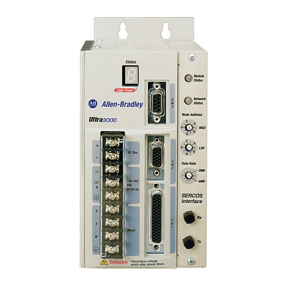
Page 41: Connectors And Indicators
DC bus connections for active shunt resistor kit AC input power connections Motor power connections Motor power cable shield clamp CN3 9-pin serial port connector CN2 15-pin motor feedback connector CN1 44-pin user I/O connector Rockwell Automation Publication 2198-RM003A-EN-P - February 2020... - Page 42 CN2 15-pin Motor Feedback Connector Resistor Kit Logic Power Status Indicator Data Rate Switch Seven Segment Status LED Sercos Interface Receive (Rx) and Transmit (Tx) Connectors Module Status Indicator CN1 44-pin User I/O Connector Rockwell Automation Publication 2198-RM003A-EN-P - February 2020...
-
Page 43: Kinetix 5100 Servo Drive Connector Data
• Reserved (P1, P2, and negative DC-bus) connections Ethernet (PORT2) RJ45 connector Motor feedback (MFB) connector Ethernet (PORT1) RJ45 connector Motor power output terminals I/O signal connector Shunt resistor terminals Auxiliary feedback (AUX) connector Rockwell Automation Publication 2198-RM003A-EN-P - February 2020... - Page 44 (Catalog numbers 2198-E2055-ERS, 2198-E2075-ERS, and 2198-E2150-ERS) 5100 CHARGE DC– Kinetix 5100 Drive, Top View Kinetix 5100 Drive, Bottom View (2198-E2055-ERS drive is shown) (2198-E2055-ERS drive is shown) Kinetix 5100 Drive, Front View (2198-E2055-ERS drive is shown) Rockwell Automation Publication 2198-RM003A-EN-P - February 2020...
-
Page 45: I/O Connector
Figure 17 - Ultra3000 Drive 44-Pin I/O Connector Pin Assignments Pin 30 Pin 15 Pin 44 Pin 31 Pin 1 Pin 16 Figure 18 - Kinetix 5100 Drive 50 Pin I/O Connector Pin Assignment Rockwell Automation Publication 2198-RM003A-EN-P - February 2020... - Page 46 Digital Input 2 INPUT2 Digital input INPUT6 Digital Input 3 INPUT3 Digital input INPUT5 Digital Input 4 INPUT4 Digital input INPUT3 Digital Input 5 INPUT5 External power input of BX+/BX- for single-end operation BPWR Rockwell Automation Publication 2198-RM003A-EN-P - February 2020...
-
Page 47: Motor Feedback Connectors
Figure 19 - 15-Pin Motor Feedback Connector Pin Assignments Pin 10 Pin 15 Pin 5 Pin 11 Pin 1 Pin 6 Rockwell Automation Publication 2198-RM003A-EN-P - February 2020... -
Page 48: Auxiliary Feedback
Figure 12 Figure 13 for locations of the auxiliary feedback connector on Ultra3000 drives. See Figure Figure 15, and Figure 16 for the locations of the auxiliary feedback connector on Kinetix 5100 drives Rockwell Automation Publication 2198-RM003A-EN-P - February 2020... - Page 49 Encoder Common Auxiliary Encoder CH I+ MTR_EPWR5V Encoder 5V Power Output Auxiliary Encoder CH I- Reserved Reserved — — — Reserved Reserved (1) CN1 Connector on the Ultra3000 drive is a 44-pin connector. Rockwell Automation Publication 2198-RM003A-EN-P - February 2020...
- Page 50 Chapter 3 Connectors and Indicators Notes: Rockwell Automation Publication 2198-RM003A-EN-P - February 2020...
-
Page 51: Ultra3000 Drive (230V) Dimensions
Table 46 - Ultra3000 Drive Dimensions Ultra3000 Drive Cat. No. mm (in.) mm (in.) mm (in.) mm (in.) 2098-DSD-005 65.02 (2.56) 13.26 (0.52) 32.77 (1.29) 72.64 2.86) 2098-DSD-005X 2098-DSD-010 98.1 (3.89) 2098-DSD-010X 2098-DSD-020 2098-DSD-020X Rockwell Automation Publication 2198-RM003A-EN-P - February 2020... - Page 52 91.44 (3.6) 50.8 (2.0) 20.32 (0.8) 243.84 (9.6) 2098-DSD-030-DN 2098-DSD-030X-DN 2098-DSD-075 2098-DSD-075X 138.68 (5.41) 88.9 (3.5) 24.89 (0.96) 247.14 (9.73) 2098-DSD-075-DN 2098-DSD-075X-DN 2098-DSD-150 2098-DSD-150X 188.97 (7.44) 139.7 (5.5) 24.6 (0.97) 241.05 (9.49) 2098-DSD-150-DN 2098-DSD-150X-DN Rockwell Automation Publication 2198-RM003A-EN-P - February 2020...
-
Page 53: Kinetix 5100 Drive Dimensions
(2.30) 2090-CTFB-MxDD Feedback Cable Cat. No. mm (in.) mm (in.) mm (in.) mm (in.) 2198-E1004-ERS 35.0 (1.37) 178 (7.0) 170 (6.68) 52.0 (2.05) 2198-E1007-ERS 50.0 (2.0) 188 (7.41) 180 (7.10) 47.0 (1.84) 2198-E1015-ERS Rockwell Automation Publication 2198-RM003A-EN-P - February 2020... - Page 54 Expansion Block 2090-K51CK-D15M 25.0 Feedback Connector Kit (0.97) 11.0 (0.43) Flying-lead Feedback Cable Additional clearance below the cable connector/connector kit is necessary to provide the recommended cable bend radius. 2090-CTFB-MxDD Feedback Cable 37.0 (1.50) Rockwell Automation Publication 2198-RM003A-EN-P - February 2020...
- Page 55 (in.) mm (in.) mm (in.) mm (in.) mm (in.) 2198-E2055-ERS 120 (4.72) 37.0 (1.47) 59.0 (2.32) 209 (8.24) 273 (10.75) 2198-E2075-ERS 141 (5.55) 16.0 (0.65) 35.0 (1.36) 225 (8.87) 312 (12.28) 2198-E2150-ERS Rockwell Automation Publication 2198-RM003A-EN-P - February 2020...
-
Page 56: Cables
50…72 mm (2…3 in.) of the drive. Table 48 - Motor Power (MP) Connector Kinetix MP or Kinetix TLP Servo Motor Terminal U = Brown V = Black W = Blue = Green/Yellow Rockwell Automation Publication 2198-RM003A-EN-P - February 2020... - Page 57 Power wires only (PW) (1) Threaded DIN connector (motor end) and bayonet connector for 2090-XXNFMP-Sxx cable. See the 2090-Series Motor Power and Feedback Transition Cables in the Kinetix Motion Accessories Technical Data, publication KNX-TD004. Rockwell Automation Publication 2198-RM003A-EN-P - February 2020...
- Page 58 • All feedback types (CA) (1) Threaded DIN connector (motor end) and bayonet connector for 2090-XXNFMP-Sxx cable. See the 2090-Series Motor Power and Feedback Transition Cables in the Kinetix Motion Accessories Specifications Technical Data, publication KNX-TD004. Rockwell Automation Publication 2198-RM003A-EN-P - February 2020...
- Page 59 For further information, see the Motion Control Accessories section in the Kinetix Motion Control Selection Guide, publication KNX-SG001, the bill of materials (BOM) configuration tool within Motion Analyzer, or ProposalWorks™ from Rockwell Automation. Rockwell Automation Publication 2198-RM003A-EN-P - February 2020...
-
Page 60: Network Cable
DSD-005x-xx, 2098-DSD-010x-xx, and 2098-DSD-020x-xx Ultra3000 drives (non-Sercos). To avoid a separate 5V DC auxiliary logic power supply, the 24V to 5V converter breakout board (catalog number 2090-U3CBB-DMxx) is used to wire the control interface (CN1) connector. Rockwell Automation Publication 2198-RM003A-EN-P - February 2020... - Page 61 Aux Power Converter (2090-U3CBB-DMxx) Aux +5V Common Cable Shield Single-phase Input Clamp 100...240V AC rms L2/N Terminal To additional Blocks* Ultra3000 drive START* STOP* CR1* * Indicates User-supplied Component 24V DC CR1* CR1* Rockwell Automation Publication 2198-RM003A-EN-P - February 2020...
- Page 62 Transformer * Single-phase Input 100...240V AC rms START * STOP * L2/N CR1 * 24V DC CR1 * Terminal M1 * Blocks * To additional CR1 * Ultra3000 drive. * Indicates User-supplied Component Rockwell Automation Publication 2198-RM003A-EN-P - February 2020...
- Page 63 L1C, L2C, P1, P2, DC– Control power input and DC bus connector (200V class drive) U, V, W Motor power output connector Ground terminals DC+, ISH, ESH Shunt Resistor Connector Input/Output signal connector-PLC and I/O functions Rockwell Automation Publication 2198-RM003A-EN-P - February 2020...
-
Page 64: Kinetix 5100 Servo Drive Power Wiring Examples
This example illustrates grounded three-phase power that is wired to three-phase Kinetix 5100 drives when phase-to-phase voltage is within drive specifications. You must supply input power components. The three-phase AC line filter is wired as shown in Figure Rockwell Automation Publication 2198-RM003A-EN-P - February 2020... - Page 65 2198-E1004-ERS, 2198-E1007-ERS, 2198-E1015-ERS, and 2198-E1020-ERS Drives with Single-phase Operation Bonded Cabinet Ground Bus Ground Grid or Power Distribution Ground Reducing the transformer output reduces motor speed. Feeder and branch short-circuit protection is not illustrated. Rockwell Automation Publication 2198-RM003A-EN-P - February 2020...
- Page 66 Mains AC Input Power AC Line Filter 230V AC Connector Output Circuit L1 (Neutral) Contactor Protection 2198-E1004-ERS, 2198-E1007-ERS, 2198-E1015-ERS, and 2198-E1020-ERS Drives with Single-phase Operation Bonded Cabinet Ground Bus Ground Grid or Power Distribution Ground Rockwell Automation Publication 2198-RM003A-EN-P - February 2020...
- Page 67 RSLogix 500 software is used to program MicroLogix 1100 or 1400 controllers. Kinetix TLP Compatible rotary motors include Kinetix TLP servo motors. Rotary Servo Motors Kinetix MP Compatible rotary motors include Kinetix MP servo motors. Rockwell Automation Publication 2198-RM003A-EN-P - February 2020...
- Page 68 AC line filters with 23 A, 30 A, and 50 A are available for Ultra3000 (460V) drive systems. External Shunt Modules 2090-UCSR-xxxx, 9101-1183, and 2090- External shunt modules are available when the Ultra3000 drive internal shunt capability is exceeded. SRxxx-xx Rockwell Automation Publication 2198-RM003A-EN-P - February 2020...
- Page 69 • MP-Series Integrated Linear Stages • MP-Series Electric Cylinders MP-Series and TL-Series Rotary Motors • LDC-Series and LDL-Series Linear Motors (MPL-A xxxx motors shown) Figure 37 - Ultra3000 Servo Drive System Architecture (DeviceNet Interface) Rockwell Automation Publication 2198-RM003A-EN-P - February 2020...
-
Page 70: Kinetix 5100 Drive System Architecture
Figure 38 - Ultra3000 Servo Drive System Architecture (Analog or Indexing) This section shows examples of typical Kinetix 5100 servo drive systems. Kinetix 5100 Drive System Kinetix 5100 drives work with different controllers and can receive commands Architecture from many different sources. Rockwell Automation Publication 2198-RM003A-EN-P - February 2020... -
Page 71: Instruction
FORCE SD GuardLogix® 5570 Safety Controllers ControlLogix 5580 Controllers or GuardLogix 5580 Safety Controllers CompactLogix 5370 Controllers or Compact GuardLogix 5370 Safety Controllers CompactLogix 5380 and 5480 Controllers or Compact GuardLogix 5380 Safety Controllers Rockwell Automation Publication 2198-RM003A-EN-P - February 2020... -
Page 72: Kinetix 5100 Drive Controlled Via Explicit Messaging
Mini-USB Interface Cable Controller Options with (with 2198-USBF filter) Explicit Messaging Capability 1585J-M8CBJM-x (shielded) or 5100 1585J-M8UBJM-x (high-flex shielded) CHARGE Ethernet Cable To Other EtherNet/IP Devices DC– Kinetix 5100 Servo Drive (2198-E1020-ERS drive is shown) Rockwell Automation Publication 2198-RM003A-EN-P - February 2020... -
Page 73: Kinetix 5100 Drive Controlled Via Pulse Train/ Analog
Kinetix 5100 drives 2198-USBC Mini-USB Interface Cable (with 2198-USBF filter) Controller Options with Pulse Train Output, Analog, or Digital I/O (indexing) 5100 CHARGE DC– Kinetix 5100 Servo Drive (2198-E1020-ERS drive is shown) Rockwell Automation Publication 2198-RM003A-EN-P - February 2020... - Page 74 Chapter 5 System Architecture Notes: Rockwell Automation Publication 2198-RM003A-EN-P - February 2020...
- Page 75 For information on how to use KNX5100C software, see the Kinetix 5100 User Manual, publication 2198-UM004. The following examples show the Ultraware software interface followed by the KNX5100C software interface and describe the differences between how they are used to configure the feature. Rockwell Automation Publication 2198-RM003A-EN-P - February 2020...
-
Page 76: Scenario 1: Analog Command To Analog Command
Analog Command, the drive operation mode must be set at T (analog torque), S (analog speed), or PT (analog position) mode (command source ID167 set as Analog Input) respectively. Figure 43 - Analog I/O Window in KNX5100C Software Rockwell Automation Publication 2198-RM003A-EN-P - February 2020... - Page 77 Figure 44 - Monitoring Output Window of Analog I/O in KNX5100C Software Ultraware software can execute commands that remove Velocity, Current, and Position Input Offsets for an online drive. KNX5100C software does not support this feature. Rockwell Automation Publication 2198-RM003A-EN-P - February 2020...
-
Page 78: Scenario 2: Indexing To Pr Mode
Figure 45 - Indexing Branch of Indexing Mode in Ultraware In Ultraware software, you can configure up to 64 indexes. The Ultra3000 drives can support move types including: • Absolute • Incremental • Jog • Registration Rockwell Automation Publication 2198-RM003A-EN-P - February 2020... - Page 79 (0x08) signal. You can program the 99 registers first before switching the drive to servo-on state and use the DI.POS0 … DI.POS6 signals as a binary weighted PR command selection. When using I/O mode, the Add-On Instructions are used to initiate PR commands. Rockwell Automation Publication 2198-RM003A-EN-P - February 2020...
-
Page 80: Scenario 3: Master/Follower Mode To Pt Mode
(these terminals double as PTO command input signals). The motor follows the input pulses based on the E-Gear ratio used. For details, see the Kinetix 5100 Single-axis EtherNet/IP Servo Drives Users Manual, publication 2198-UM004. Rockwell Automation Publication 2198-RM003A-EN-P - February 2020... - Page 81 Application Conversion Chapter 6 PT command configuration mode in KNX5100C software is shown in Figure Figure 48 - PT Mode Window in KNX5100C Software Rockwell Automation Publication 2198-RM003A-EN-P - February 2020...
-
Page 82: Scenario 4: Devicenet To I/O Mode
Logix Designer application provides the Input Assembly for monitoring and the Output Assembly for motion control (position, velocity, torque, and indexing). Additionally, Add-On Instructions are provided to emulate Logix 5000 controller motion instructions for application programming. Rockwell Automation Publication 2198-RM003A-EN-P - February 2020... -
Page 83: Scenario 5: Host Command To Explicit Messaging
This example shows how to replace the indexing function through the host commands of the Ultra3000 drive by using Explicit Messaging on the Kinetix 5100 drive: Rockwell Automation Publication 2198-RM003A-EN-P - February 2020... - Page 84 UDINT Value (3000, unit is 0.1 RPM)’ . • Set PR Command2 Setting (for example, positioning control) by explicit message ‘Set Attribute Single (16), Class 15, Instance 401, Attribute 1, UDINT Value (0x00000002)’ . Rockwell Automation Publication 2198-RM003A-EN-P - February 2020...
- Page 85 • Stop the PR Command by explicit message ‘Set Attribute Single (16), Class 15, Instance 300, Attribute 1, UINT Value (1000)’ . • Get the status of PR Command by explicit message ‘Get Attribute Single (14), Class 15, Instance 300, Attribute 1’ . Rockwell Automation Publication 2198-RM003A-EN-P - February 2020...
- Page 86 Chapter 6 Application Conversion Notes: Rockwell Automation Publication 2198-RM003A-EN-P - February 2020...
- Page 87 *Configurable in KNX5100C software Dual Loop Control — — — Yes* *PT mode only Multiple Motors Supported Yes* * Kinetix MP Motor, TLP Motor Dual-port Ethernet with DLR support — — — — Rockwell Automation Publication 2198-RM003A-EN-P - February 2020...
- Page 88 * Not natively, programming required Batch Count — — Yes* * Not natively, programming required Homing, Active/Switch/Marker — Homing, Absolute — Home to Torque Limit — — — — Define Home current position — Stop Indexing — Rockwell Automation Publication 2198-RM003A-EN-P - February 2020...
- Page 90 Rockwell Automation maintains current product environmental information on its website at http://www.rockwellautomation.com/rockwellautomation/about-us/sustainability-ethics/product-environmental-compliance.page. Allen-Bradley, CompactLogix, Connected Components Workbench, ControlFLASH, ControlLogix, GuardLogix, Kinetix, Logix 5000, Logix PAC, MicroLogix, Micro800, Micro830, PanelView, POINT I/O, Rockwell Automation, Rockwell Software, RSLinx, RSLogix 500, Stratix, Studio 5000, and Studio 5000 Logix Designer are trademarks of Rockwell Automation, Inc.
Need help?
Do you have a question about the Allen-Bradley Ultra3000 and is the answer not in the manual?
Questions and answers