Sign In
Upload
Manuals
Brands
Rockwell Automation Manuals
Servo Drives
Allen-Bradley Ultra3000
Rockwell Automation Allen-Bradley Ultra3000 Manuals
Manuals and User Guides for Rockwell Automation Allen-Bradley Ultra3000. We have
4
Rockwell Automation Allen-Bradley Ultra3000 manuals available for free PDF download: Integration Manual, Migration Manual, Manual
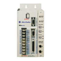
Rockwell Automation Allen-Bradley Ultra3000 Integration Manual (180 pages)
Digital Servo Drives
Brand:
Rockwell Automation
| Category:
Servo Drives
| Size: 4.92 MB
Table of Contents
Table of Contents
3
Preface
7
About this Publication
7
Who Should Use this Manual
7
Conventions Used in this Manual
7
Additional Resources
8
Commissioning Your Ultra3000 Drive
9
Introduction
9
General Startup Precautions
10
Understanding the Serial Connection
10
Configuring Your Ultra3000 Drive and Ultra3000 Drive with Indexing
11
Front Panel Connections
11
Apply Power to Your Ultra3000 Drive
15
Detect Your Ultra3000 Drive
16
Understanding the Workspace and Drive Branches
17
Select a Motor
21
Tune Your Motor
22
Configure Displayed Units
23
Test Your Motor (Non-Indexing Move)
25
Test Your Motor (Indexing Move)
26
Indexing and Non-Indexing Move Examples
29
Analog Position Mode (Non-Indexing)
32
Preset Velocity Control (Non-Indexing)
34
Preset Position Control (Indexing Move)
37
Master Follower and Preset Gear Ratios (Non-Indexing Move)
40
Incremental Indexing (Indexing Move)
44
Absolute Indexing (Indexing Move)
48
Configuring Your Ultra3000 Drive with
52
Rslogix 5000 Software
52
Configure Your Ultra3000 Drive
52
Configuring Your Logix Analog Motion Module
53
Download Your Program
58
Testing and Tuning Your Axis
59
Configuring Your Ultra3000 Drive with SERCOS
65
Front Panel Connections
65
Configure Your Ultra3000-SE Drive
70
Configuring Your Logix SERCOS Interface Module
72
Download Your Program
80
Apply Power to Your Ultra3000 Drive with SERCOS
81
Testing and Tuning Your Axis
83
Configuring Your Ultra3000 Drive with Devicenet
89
Front Panel Connections
89
Configure Your Ultra3000 Drive with Devicenet
93
Apply Power to Your Ultra3000 Drive with Devicenet
94
Troubleshooting Your Ultra3000 Servo Drive
97
Introduction
97
Safety Precautions
97
General Troubleshooting
98
Error Codes
98
Troubleshooting for SERCOS Drives
104
Understanding Drive Fault Behavior
105
Troubleshooting for Devicenet Drives
109
Node Problems
110
Device Failure - Indicator Status Check
110
Scanner Problems
111
Power Supply Problems
111
Cable Installation and Design Problems
112
Adjusting the Physical Network Configuration
112
Interconnect Diagrams
113
Introduction
113
Wiring Examples
114
Power Interconnect Diagrams
115
Shunt Module Interconnect Diagrams
119
Ultra3000 Drives/Rotary Motors and Actuators Wiring Examples
122
Ultra3000 Drives/Linear Actuators Wiring Examples
127
Control String Examples (120V Ac)
128
Controlling a Brake Example
131
Ultra3000 Drive to Logix Analog Module Diagrams
133
Ultra3000 Drive to IMC-S Compact Controller Diagram
136
Understanding Motor Feedback Signals and Outputs
137
Introduction
137
Unbuffered Encoder Outputs
138
Incremental Encoder Outputs
138
High Resolution Encoder Outputs
139
Minimizing the Effects of Feedback Signal Loss
141
Introduction
141
Rslogix 5000 Software
142
Minimizing the Position Error Limit Setting
142
Setting Position Error Limits in Ultraware and Rslogix 5000 Software
142
Setting Velocity Error Limits in Ultraware Software
144
Minimizing the Velocity Error Limit Setting
144
Configuring Fault Actions in Rslogix 5000 Software
145
Position and Velocity Error Limit Adjustment Example with Ultraware Software
147
Create and Run a Sample Application in Ultraware Software
147
Understanding Error Limit Settings in Ultraware Software
149
Use the Oscilloscope Feature
150
Interpreting the Results
153
Position Error Limit Adjustment Example with
154
Rslogix 5000 Software
154
Run the Rslogix 5000 Software Example Program
155
Observe the Default Position Error Tolerance Limit Setting
156
Trending Excursion Limits of the Position Error
159
Parameter
159
Set the New Position Error Limit
163
Verify the New Position Error Limit
164
Visualize the New Position Error Limit
166
Additional Methods
166
Exporting and Importing Drive Setup Files
167
Introduction
167
Export a Drive Setup File
167
Import a Drive Setup File
169
Advertisement
Rockwell Automation Allen-Bradley Ultra3000 Migration Manual (90 pages)
Brand:
Rockwell Automation
| Category:
Servo Drives
| Size: 6.01 MB
Table of Contents
Table of Contents
3
Integrated Architecture Builder Software
5
Motion Analyzer Software
5
Overview
5
Preface
5
Additional Resources
6
Migration Services
6
Migration Options
9
Chapter 1 Kinetix 5100 Servo Drive Catalog Numbers
10
Potential Design Changes
11
Chapter 2 Before You Begin
13
Selecting a Replacement Drive
14
Nominal Voltage and Output Current Comparison
15
Dimension Comparison
16
AC Input Power Wiring and Fusing
16
AC Input Power Wiring
16
Circuit Breaker and Fuse Considerations
17
Power Specifications
19
I/O Availability and Specifications
22
Digital Inputs
22
Functionality Inputs
23
Digital Outputs
25
Analog Inputs
28
Analog Output
29
Control and Auxiliary Power Specifications
31
Motors
32
Feedback Devices
32
Accessories
32
Required Drive Accessories
33
Optional Drive Accessories - Ethernet Cable
33
Optional Drive Accessories - Shunt Resistors
34
Optional Drive Accessories - AC Line Filters
36
Communication
38
Ultra3000 Servo Drive Configuration Port
38
Kinetix 5100 Servo Drive Configuration Port
38
Ultra3000 Servo Drive Control Port
38
Kinetix 5100 Servo Drive Control Port
39
Configuration and Programming Software
39
Replacement Considerations
13
Chapter 3
41
Connectors and Indicators
41
Ultra3000 Servo Drive Connector Data
41
Kinetix 5100 Servo Drive Connector Data
43
I/O Connector
45
Motor Feedback Connectors
47
Auxiliary Feedback
48
Ultra3000 Drive (230V) Dimensions
51
Chapter 4
53
Kinetix 5100 Drive Dimensions
53
Cables
56
Motor Power and Feedback Cables
56
Network Cable
60
Mini-USB Cable
60
Wiring
60
Ultra3000 Servo Drive Power Wiring Examples
60
Kinetix 5100 Servo Drive Power Wiring Examples
64
Chapter 5 Kinetix 5100 Drive System Architecture
70
Instruction
71
Kinetix 5100 Drive Controlled Via Explicit Messaging
72
Kinetix 5100 Drive Controlled Via Pulse Train/ Analog
73
Digital I/O
73
Scenario 1: Analog Command to Analog Command
76
Chapter 6
78
Scenario 2: Indexing to PR Mode
78
Scenario 3: Master/Follower Mode to PT Mode
80
Scenario 4: Devicenet to I/O Mode
82
Scenario 5: Host Command to Explicit Messaging
83
Rockwell Automation Allen-Bradley Ultra3000 Manual (80 pages)
Digital Servo Drives to Kinetix 5300 Servo Drives
Brand:
Rockwell Automation
| Category:
Servo Drives
| Size: 7.83 MB
Table of Contents
Table of Contents
3
Preface
5
Pre-Migration
5
Select a Replacement Drive
6
Engineering Effort and Product Liability
6
Migration Options
6
Additional Resources
7
Servo Drive and System
9
Kinetix 5300 Servo Drives
9
Kinetix 5300 Servo Drive Features
9
Kinetix 5300 Servo Drive Components
10
Kinetix 5300 Servo Drive Selection
10
Communication
11
Controller, Ethernet Cards, and Switches
12
Compatible Motors and Acuators
12
Cable Lengths
13
Physical Dimensions
13
Control and Auxiliary Power
13
Circuit Protection
14
Control Signals
14
Safe Torque off Safety Features
15
Drive Accessories
15
Servo Drive and System
17
Drive Replacement
17
Output Current Comparison
17
Dimension Comparison
19
Dimension Drawings
20
AC Input Power Cable Length and Fuse Protection
25
AC Input Power Cable Lengths
25
Circuit Breaker and Fuse Considerations
27
Drive Interconnects and Cable Considerations
30
Ultra3000 Servo Drives Motor/Actuator and Cable Compatibility
30
Ultra3000 Servo Drive Feedback Connector
31
Kinetix 5300 Servo Drives Servo Motor/Actuator and Cable Compatibility
32
Digital I/O
35
Ultra3000 Servo Drive Digital Inputs
35
Ultra3000 Servo Drive Outputs
36
Kinetix 5300 Servo Drive Digital Inputs
37
Typical System Layout
38
Ultra3000 Servo Drive System Example
38
Kinetix 5300 Servo Drive System Example
39
Accessories
39
Ultra3000 Servo System Accessories
39
Kinetix 5300 Servo System Accessories
41
Connector Locations
43
Ultra3000 Servo Drive Connector Data
43
Kinetix 5300 Servo Drive Connector Data
47
Input and Motor Power Connector Pinouts
47
Motor Feedback
49
I/O Connector and Auxiliary Feedback Pinouts
49
Safe Torque off Connector
51
About the Ultra3000 Servo Drive System
53
About the Kinetix 5300 Servo Drive System
54
Power Specifications
55
Ultra3000 (230V) Servo Drive Power Specifications
55
Ultra3000 (460V) Servo Drive Power Specifications
57
Kinetix 5300 Servo Drive Input Power Specifications
58
Control and Auxiliary Power Specifications
61
Ultra3000 Servo Drive Auxiliary Power Specifications
61
Kinetix 5300 Servo Drive Control Power Specifications
62
Power Dissipation Specifications
63
Ultra3000 Servo Drive Power Dissipation Specifications
63
Kinetix 5300 Servo Drive Power Dissipation Specifications
63
Cable Lengths
64
Ultra3000 Servo Drive Motor Feedback Cable Lengths
64
Kinetix 5300 Servo Drive Motor Cable Lengths
65
Environmental Specifications
65
Ultra3000 Servo Drive Environmental Specifications
65
Kinetix 5300 Servo Drive Environmental Specifications
65
Certifications
66
Ultra3000 Servo Drive Certifications
66
Kinetix 5300 Servo Drive Certifications
66
Ultra3000 Servo Drive Power Wiring Examples
67
Kinetix 5300 Servo Drive Power Wiring Examples
71
Kinetix 5300 Servo Drive Linear Topology
76
Ring Topology
77
Star Topology
78
Advertisement
Rockwell Automation Allen-Bradley Ultra3000 Migration Manual (96 pages)
Brand:
Rockwell Automation
| Category:
Servo Drives
| Size: 9.1 MB
Table of Contents
Table of Contents
3
Preface
5
Summary of Changes
5
Overview
6
Integrated Architecture Builder Software
6
Motion Analyzer Software
6
Migration Services
6
Additional Resources
7
Kinetix 5100 Servo Drive Catalog Numbers
10
Drive Sizing
14
AC Input Power Wiring and Fusing
17
Power Specifications
19
I/O Availability and Specifications
26
Feedback Devices
35
Accessories
35
Communication
40
Ultra3000 Servo Drive Connector Data
43
Kinetix 5100 Servo Drive Connector Data
46
I/O Connector
49
Motor Feedback Connectors
51
Auxiliary Feedback
52
Ultra3000 Drive (230V) Dimensions
55
Kinetix 5100 Drive Dimensions
58
Cables
61
Power Wiring
66
Kinetix 5100 Drive System Architecture
77
Scenario 1: Analog Command to Analog Command
82
Scenario 2: Indexing to PR Mode
84
Scenario 3: Master/Follower Mode to PT Mode
86
Scenario 4: Devicenet to
88
I/O Mode
88
Scenario 5: Host Command to Explicit Messaging
90
Advertisement
Related Products
Rockwell Automation Allen-Bradley Kinetix 6000
Rockwell Automation Allen-Bradley Kinetix VP Series
Rockwell Automation Allen-Bradley Kinetix 5500 Series
Rockwell Automation Allen-Bradley Kinetix 2000
Rockwell Automation Allen-Bradley Kinetix TLP Series
Rockwell Automation Allen-Bradley Kinetix 7000
Rockwell Automation Allen-Bradley Kinetix 5500
Rockwell Automation Allen-Bradley 2198-H***-ERS Series
Rockwell Automation Allen-Bradley 2198-H003-ERS
Rockwell Automation Allen-Bradley 2198-H008-ERS
Rockwell Automation Categories
Controller
Control Unit
Power Supply
DC Drives
Industrial Equipment
More Rockwell Automation Manuals
Login
Sign In
OR
Sign in with Facebook
Sign in with Google
Upload manual
Upload from disk
Upload from URL