
Related Manuals for Rockwell Automation Allen-Bradley Kinetix 3 2071-AP0


Summary of Contents for Rockwell Automation Allen-Bradley Kinetix 3 2071-AP0
- Page 1 User Manual Kinetix 3 Component Servo Drives Catalog Numbers 2071-AP0, 2071-AP1, 2071-AP2, 2071-AP4, 2071-AP8, 2071-A10, 2071-A15...
- Page 2 Identifies information that is critical for successful application and understanding of the product. Allen-Bradley, Kinetix, LDC-Series, LDL-Series, MicroLogix, MP-Series, Rockwell Automation, Rockwell Software, RSLogix 500, RSLogix 5000, TechConnect, and TL-Series are trademarks of Rockwell Automation, Inc. Trademarks not belonging to Rockwell Automation are property of their respective companies.
-
Page 3: About This Publication
Kinetix 3 drive. If you do not have a basic understanding of the Kinetix 3 drive, contact your local Rockwell Automation sales representative for information on available training courses. Conventions Used in This The conventions starting below are used throughout this manual. -
Page 4: Additional Resources
AG-7.1 A glossary of industrial automation terms and abbreviations. You can view or download publications at http://www.rockwellatuomation.com/literature. To order paper copies of technical documentation, contact your local Rockwell Automation distributor or sales representative. Rockwell Automation Publication 2071-UM001B-EN-P - October 2010... -
Page 5: Table Of Contents
Serial Interface Connection ........43 Rockwell Automation Publication 2071-UM001B-EN-P - October 2010... - Page 6 Test Your Motor (indexing move)......92 Rockwell Automation Publication 2071-UM001B-EN-P - October 2010...
- Page 7 Motor Brake Currents ........118 Rockwell Automation Publication 2071-UM001B-EN-P - October 2010...
- Page 8 Table of Contents Rockwell Automation Publication 2071-UM001B-EN-P - October 2010...
-
Page 9: Introduction
Use this chapter to become familiar with the Kinetix 3 drive components. This chapter also reviews design and installation requirements for Kinetix 3 drive systems. Topic Page Introduction About the Kinetix 3 Drive System Agency Compliance Rockwell Automation Publication 2071-UM001B-EN-P - October 2010... -
Page 10: About The Kinetix 3 Drive System
SLC 500 and MicroLogix controller families. 2090-CCMPCDS-23AAxx Serial communication cables provide an interface Serial communication cables 2090-CCMCNDS-48AAxx between your system components by using RS-232 or RS- 485 protocols. 2090-CCMDSDS-48AAxx Rockwell Automation Publication 2071-UM001B-EN-P - October 2010... - Page 11 MicroLogix 1400 Controller 2090-CCMCNDS-48AAxx Controller Cable 2090-DANFCT-Sxx 2071-Axxxx Motor Feedback Cable Kinetix 3 Servo Drives 2071-Axxxx Kinetix 3 Servo Drive 2090-DANPT-16Sxx Motor Power Cable 2090-CCMDSDS-48AAxx Drive-to-Drive Cable TL-Series Rotary Motors (TL-Axxxx motor shown) Rockwell Automation Publication 2071-UM001B-EN-P - October 2010...
-
Page 12: Catalog Number Explanation
Use shielded cable for power wiring and provide a grounded 360° clamp termination. Refer to Appendix B page 113 for interconnect diagrams, including input power wiring and drive/motor interconnect diagrams. Rockwell Automation Publication 2071-UM001B-EN-P - October 2010... -
Page 13: Introduction
• Size the drive enclosure so as not to exceed the maximum ambient temperature rating. Consider heat dissipation specifications for all drive components. Rockwell Automation Publication 2071-UM001B-EN-P - October 2010... -
Page 14: Fuse Selection
Refer to Fuse/Contactor Specifications on page 105 for recommended fuses. Refer to Kinetix 3 Drive Power Specifications on page 104 for input current and inrush current specifications for your Kinetix 3 drive. Rockwell Automation Publication 2071-UM001B-EN-P - October 2010... -
Page 15: Sizing The Enclosure
Because this cabinet size is considerably larger than what is necessary to house the system components, it may be more efficient to provide a means of cooling in a smaller cabinet. Contact your cabinet manufacturer for options available to cool your cabinet. Rockwell Automation Publication 2071-UM001B-EN-P - October 2010... -
Page 16: Minimum Clearance Requirements
Allow 30 mm (1.18 in.) clearance to side wall of enclosure. Allow 10 mm (0.39 in.) 50.0 mm (2.0 in.) clearance clearance between drives. for airflow and Installation. Refer to page 106 for power dissipation specifications. Rockwell Automation Publication 2071-UM001B-EN-P - October 2010... -
Page 17: Electrical Noise Reduction
Improper bonding of metal surfaces blocks the direct return path and allows high-frequency energy to travel elsewhere in the cabinet. Excessive high- frequency energy can effect the operation of other microprocessor controlled equipment. Rockwell Automation Publication 2071-UM001B-EN-P - October 2010... - Page 18 Flat Washer Star Washer Flat Washer If the mounting bracket is coated with a non-conductive material Star Washer (anodized or painted), scrape the material around the mounting hole. Rockwell Automation Publication 2071-UM001B-EN-P - October 2010...
-
Page 19: Bonding Multiple Subpanels
Figure 5 - Multiple Subpanels and Cabinet Recommendations Wire Braid. 25.4 mm (1.0 in.) by 6.35 mm (0.25 in.) Ground bus bonded to the subpanel. Wire Braid. Remove paint 25.4 mm (1.0 in.) by from cabinet. 6.35 mm (0.25 in.) Rockwell Automation Publication 2071-UM001B-EN-P - October 2010... -
Page 20: Establishing Noise Zones
(3) This is a clean 24V DC available for any device that may require it. The 24V enters the clean wireway and exits to the left. (4) This is a dirty 24V DC available for motor brakes and contactors. The 24V enters the dirty wireway and exits to the right. Rockwell Automation Publication 2071-UM001B-EN-P - October 2010... -
Page 21: Cable Categories For Kinetix 3 Drive Components
The brake is mounted inside the motor. How you connect to the drive depends on the motor series. Refer to Kinetix 3 Drive/Rotary Motor Wiring Examples beginning on page 114 for the interconnect diagram of your drive/motor combination. Rockwell Automation Publication 2071-UM001B-EN-P - October 2010... -
Page 22: Mount Your Kinetix 3 Drive
1.1 N•m (9.8 lb•in). Observe bonding techniques as described Bonding Drives on page IMPORTANT To improve the bond between the Kinetix 3 drive and subpanel, construct your subpanel out of zinc plated (paint-free) steel. 3. Tighten all mounting fasteners. Rockwell Automation Publication 2071-UM001B-EN-P - October 2010... -
Page 23: Introduction
Introduction This chapter provides power, feedback, and I/O connector locations and signal descriptions for your Kinetix 3 drive. Topic Page Introduction Kinetix 3 Drive Connectors and Indicators Motor Feedback Specifications Control Signal Specifications Rockwell Automation Publication 2071-UM001B-EN-P - October 2010... -
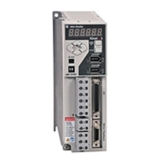
Page 24: Kinetix 3 Drive Connectors And Indicators
Main power indicator Enter key Shunt resistor (BC) connector Mode/set key Motor power (MP) connector 7-segment status indicator Ground lug 2071-AP0 Kinetix 3 drive shown 2071-AP4 Kinetix 3 and larger drives have 2 ground screws. Rockwell Automation Publication 2071-UM001B-EN-P - October 2010... - Page 25 AOUT1 Analog output #1 ground ACOM Analog output #2 AOUT2 Analog output #2 ground ACOM Figure 8 - Pin Orientation for 4-pin Header (A.out) Connector Pin 2 Pin 4 Pin 1 Pin 3 Rockwell Automation Publication 2071-UM001B-EN-P - October 2010...
-
Page 26: I/O (Iod) Connector Pinout
O/C for pulse of 24V level 24V_PULS + O/C for sign of 24V level 24V_SIGN + Reserved — Figure 9 - Pin Orientation for 50-pin I/O (IOD) Connector Pin 1 Pin 26 Pin 25 Pin 50 Rockwell Automation Publication 2071-UM001B-EN-P - October 2010... -
Page 27: Motor Feedback (Mf) Connector Pinout
RS-232 transmit RS-232 receive Reserved — +5V power ground RS-485 + RS-485 - Figure 11 - Pin Orientation for 6-pin Serial Interface (Comm0A and CommOB) Connector Pin 2 Pin 6 Pin 5 Pin 1 Rockwell Automation Publication 2071-UM001B-EN-P - October 2010... -
Page 28: Input Power Connector Pinout
Shunt resistor + DC bus positive (not supported) Shunt resistor - Motor Power Connector Pinout Table 9 - Motor Power (MP) Connector MP Pin Description Signal Motor power U Motor power V Motor power W Rockwell Automation Publication 2071-UM001B-EN-P - October 2010... -
Page 29: Motor Feedback Specifications
• Generic TTL incremental with Hall and Feedback device support thermistor sensors • 17-bit Serial Power supply voltage (EPWR5V) 5.08…5.45V Power supply current (EPWR5V) 300 mA, max Single-ended, under 1.6 k= no fault, over Thermostat 3.2 k= fault Rockwell Automation Publication 2071-UM001B-EN-P - October 2010... -
Page 30: Motor Feedback Specifications
– – – – – – -LIMIT – DATA+ – – – – – DATA- – – – – +LIMIT – – BAT+ – BAT- EPWR EPWR (1) If thermal sensor is used. Rockwell Automation Publication 2071-UM001B-EN-P - October 2010... - Page 31 Figure 12 - Motor Thermostat Interface Kinetix 3 Drive 6.8 kΩ 1 kΩ 0.01 µF State Resistance at TS No Fault 1.6 k Fault 3.2 k Rockwell Automation Publication 2071-UM001B-EN-P - October 2010...
- Page 32 BM + or IM+ AM - BM - or IM - Figure 14 - Generic TTL Interface, S1, S2, or S3 Signals Kinetix 3 Drive 4.7 kΩ or S3 1 kΩ 10 nF Rockwell Automation Publication 2071-UM001B-EN-P - October 2010...
-
Page 33: Feedback Power Supply
Table 14 - Motor Feedback Power Specifications Attribute Value Signal EPWR 5.08 Voltage nominal 5.25 5.45 Current, mA Figure 15 - Pin Orientation for 20-pin Motor Feedback (MF) Connector Pin 1 Pin 11 Pin 10 Pin 20 Rockwell Automation Publication 2071-UM001B-EN-P - October 2010... -
Page 34: Control Signal Specifications
• Start Homing • Start Indexing • Stop Homing • Stop Indexing • Pause Indexing • Index Select 0 • Index Select 1 • Index Select 2 • Index Select 3 • Index Select 4 Rockwell Automation Publication 2071-UM001B-EN-P - October 2010... - Page 35 Specifications. The inputs can be set up for PNP sourcing or NPN sinking. Figure 16 - Digital Inputs (PNP sourcing configuration) Kinetix 3 24V IN Drive 3.3 KΩ 4.7 KΩ 24V Supply 3300 Ω 0.01 µF Opto-coupler INPUTS Logic GND Rockwell Automation Publication 2071-UM001B-EN-P - October 2010...
- Page 36 On-state current at min voltage 6.3 mA On-state current at max voltage 7.71 mA Off-state voltage, max Off-state current, max 0 mA Hardware delay, off to on 8.4 µs Hardware delay, on to off 50.1 µs Rockwell Automation Publication 2071-UM001B-EN-P - October 2010...
-
Page 37: Digital Outputs
The fault outputs, FAULT1…FAULT3, can be reassigned through the parameter setting giving you three additional digital outputs, OUTPUT4…OUTPUT6. The drive contains four alarm outputs. The four alarm outputs include the alarm signals FAULT+ and FAULT- and three bits of fault information, FAULT1…FAULT3. Rockwell Automation Publication 2071-UM001B-EN-P - October 2010... - Page 38 E.012 Home Search Failed E.027 Axis Not Homed E.060 Drive Initialization Fault E.100 Drive Setup Fault Digital and fault outputs are grounded through FCOM/OUT COM. All digital outputs are active low, current sinking. Rockwell Automation Publication 2071-UM001B-EN-P - October 2010...
- Page 39 Maximum on-state voltage drop @ 50 mA 1.2mV DC Hardware delay, off to on, max 2.36 ms Hardware delay, on to off, max 310 ms Figure 18 - Digital Outputs Logic Power 200 Ω OUTPUT1+ OUTPUT1- TLP127 Rockwell Automation Publication 2071-UM001B-EN-P - October 2010...
-
Page 40: Analog Inputs
[which is 2 ICMD 12 bits — Resolution Input Open circuit impedance measured between the 10 k — Impedance positive (+) input and analog common. Input Signal Voltage applied to the input -10V +10V Range Rockwell Automation Publication 2071-UM001B-EN-P - October 2010... -
Page 41: Analog Outputs
• Bus Voltage • Velocity Command Offset • Current Command Offset • Motor Temperature • Analog Command – Velocity • Analog Command – Current Figure 20 shows the configuration of the analog outputs. Rockwell Automation Publication 2071-UM001B-EN-P - October 2010... - Page 42 12 Bits — (to the number of bits) into, which is 2 Output Current capability of the output. -10 mA +10 mA Current Output Range of the output voltage. -10V +10V Signal Range Rockwell Automation Publication 2071-UM001B-EN-P - October 2010...
-
Page 43: Serial Interface Connection
Table 19 - RS-485 Serial Communication Specifications Attribute Value Communication Protocol RS-485 Baud 192,000 Data bits Parity None Stop bit Operator interface bit pattern 1102 Cabling Catalog numbers 2090-CCMCNDS and 2090-CCMDSDS Rockwell Automation Publication 2071-UM001B-EN-P - October 2010... - Page 44 Chapter 3 Kinetix 3 Drive Connector Data Notes: Rockwell Automation Publication 2071-UM001B-EN-P - October 2010...
-
Page 45: Introduction
National Electrical Code, local electrical codes, special operating temperatures, duty cycles, or system configurations take precedence over the values and methods provided. Rockwell Automation Publication 2071-UM001B-EN-P - October 2010... -
Page 46: Building Your Own Cables
Electrical Noise Reduction page 17 for examples of routing high and low voltage cables in wireways. Refer to the System Design for Control of Electrical Noise Reference Manual, publication GMC-RM001, for more information. Rockwell Automation Publication 2071-UM001B-EN-P - October 2010... -
Page 47: Determining Your Type Of Input Power
Figure 22 - Three-phase Power Configuration (Delta secondary) Transformer (Delta) Secondary IPD Terminals AC Line Filter Kinetix 3 Drive Three-phase AC Input Grounded Center-tap (Optional) Bonded Cabinet Ground Bus Ground Grid or Power Distribution Ground Rockwell Automation Publication 2071-UM001B-EN-P - October 2010... - Page 48 Transformer (Delta) Secondary AC Line Filter Kinetix 3 Drive Three-phase AC Input Bonded Cabinet Ground Bus Corner Grounded (Optional) Ground Grid or Power Distribution Ground Feeder and branch short circuit protection is not illustrated. Rockwell Automation Publication 2071-UM001B-EN-P - October 2010...
-
Page 49: Single-Phase Power Wired To Single-Phase Drives
When using an isolation transformer, attach a chassis ground wire to the neutral connection. This accomplishes the following: • Prevents the system from floating and thereby avoids any high voltages that might otherwise occur, for example due to static electricity. Rockwell Automation Publication 2071-UM001B-EN-P - October 2010... -
Page 50: Three-Phase Power Wired To Single-Phase Drives
If a three-phase line filter is used to feed multiple single-phase drives (not recommended), it is important that the filter include a neutral connection as shown above. This applies if three-phase is brought directly into the filter and no isolating transformer is present. Rockwell Automation Publication 2071-UM001B-EN-P - October 2010... -
Page 51: Grounding Your Kinetix 3 Drive
Figure 26 - Connecting the Braided Ground Strap Example For dimensions, See Product Dimensions on page 109. Item Description Mounting Screw Braided Ground Strap Bonded Cabinet Ground Bus Ground Grid or Power Distribution Ground Rockwell Automation Publication 2071-UM001B-EN-P - October 2010... - Page 52 For information, refer to Bonding Multiple Subpanels on page Figure 28 - Subpanels Connected to a Single Ground Point Always follow NEC and applicable local codes. Bonded Ground Ground Grid or Power Distribution Ground Rockwell Automation Publication 2071-UM001B-EN-P - October 2010...
-
Page 53: Power Wiring Requirements
To avoid personal injury and/or equipment damage, make sure shielded power cables are grounded to prevent potentially high voltages on the shield. IMPORTANT The National Electrical Code and local electrical codes take precedence over the values and methods provided. Rockwell Automation Publication 2071-UM001B-EN-P - October 2010... -
Page 54: Shunt Resistor Power Wiring Requirement
Appendix 4. Gently pull on each wire to make sure it does not come out of its terminal; reinsert and tighten any loose wires. 5. Insert the connector plug into the drive connector. Rockwell Automation Publication 2071-UM001B-EN-P - October 2010... -
Page 55: Wiring The Kinetix 3 Drive Connectors
IMPORTANT For TL-Series motors, also connect the 152 mm (6.0 in.) termination wire to the closest earth ground. Refer to Pigtail Terminations on page 56 for more information. Rockwell Automation Publication 2071-UM001B-EN-P - October 2010... - Page 56 MP-Series (Bulletin MPAS) MPAS-Axxxx or 2090-CPBM4DF-xxAFxx (continuous-flex) (continuous-flex) Rectangular 2090-DANPT-16Sxx for power TL-Series (Bulletin TL) TL-Axxxx-B 2090-DANPT-16Sxx plastic 2090-DANBT-18Sxx for brake TL-Series (Bulletin TLY) TLY-Axxxx Circular 2090-CPBM6DF-16AAxx 2090-CPWM6DF-16AAxx plastic (standard) (standard) TL-Series (Bulletin TLAR) TLAR-Axxxx Rockwell Automation Publication 2071-UM001B-EN-P - October 2010...
- Page 57 Motor power (MP) connector plug Drive ground screw Motor cable ground wire Cable shield is tied to the ground wire in the cable. No further grounding is required with motor power cable, catalog number 2090-DANPT-16Sxx. Rockwell Automation Publication 2071-UM001B-EN-P - October 2010...
- Page 58 Description 2071-AP4 Kinetix 3 drive shown Motor power cable Ground wire Ground lug - user supplied Cable shield clamp Ground and secure the motor power cable in your system following instructions page 62. Rockwell Automation Publication 2071-UM001B-EN-P - October 2010...
- Page 59 (3) Diode 1N4004 rated 1.0A @ 400V DC. See Power Wiring Examples beginning on page 114. (4) Exposed shield under clamp and place within 50…75 mm (2…3 in). of drive, see page 62 for details. Rockwell Automation Publication 2071-UM001B-EN-P - October 2010...
- Page 60 MP-Series, TL-Series MP Pin Signal U / Brown V / Black W / Blue Green/yellow ground wire with ring lug is connected to the screw provided on the drive. Shown Figure on page Rockwell Automation Publication 2071-UM001B-EN-P - October 2010...
-
Page 61: Shunt Resistor
The information supplied here is for reference only. There are no adjustments or user serviceable parts associated with the shunt resistor. Figure 36 - Shunt Resistor (BC) Connector Kinetix 3 Drive Front view is shown. Shunt Resistor (BC) Connector Rockwell Automation Publication 2071-UM001B-EN-P - October 2010... -
Page 62: Apply The Motor Cable Shield Clamp
4. Position the exposed portion of the cable braid directly in line with the clamp. 5. Clamp the exposed shield to the panel with the clamp and two #6-32 x 1 screws provided. 6. Repeat steps 1…5 for each Kinetix 3 drive you are installing. Rockwell Automation Publication 2071-UM001B-EN-P - October 2010... -
Page 63: Feedback And I/O Cable Connections
High-resolution encoder 2090-CFBM6DF-CBAAxx TLAR-Axxxxx page 64 (standard) TLY-Axxxx-H Incremental encoder TL-Axxxx-B High-resolution encoder 2090-DANFCT-Sxx 2090-DANFCT-Sxx page 65 (1) Remove the premolded connector on the drive end and use Feedback Breakout Board, catalog number 2071-TBMF. Rockwell Automation Publication 2071-UM001B-EN-P - October 2010... -
Page 64: Flying-Lead Feedback Cable Pin-Outs
AM - BM + BM - IM + IM - S1 + S1 - — — S2 + S2 - — — S3 + S3 - — — EPWR 5V EPWR ECOM ECOM SHIELD Rockwell Automation Publication 2071-UM001B-EN-P - October 2010... - Page 65 Motor Drive Drive MF Connector Pin Signal Name Signal Name Connector Pin EPWR EPWR ECOM/BAT - ECOM (internally connected) BAT- SHIELD DATA + SD + DATA - SD - BAT + BAT + Rockwell Automation Publication 2071-UM001B-EN-P - October 2010...
-
Page 66: Wiring The I/O Connector
I/O interface cable, catalog number 2090-DAIO-D50xx provides access to all 50 pins of I/O. Figure 38 - Kinetix 3 Drive (IOD connector and I/O Interface cable) 2090-DAIO-D50xx I/O Interface Cable I/O (IOD) Connector Rockwell Automation Publication 2071-UM001B-EN-P - October 2010... -
Page 67: Wiring The Feedback Connector
Figure 39 - Kinetix 3 Drive (MF connector) Kinetix 3 Drive, Side View Kinetix 3 Drive Front View (2071-AP4 drive is shown) (2071-AP4 drive is shown) Premolded Connector 2090-DANFCT-Sxx Cable Motor Feedback (MF) Connector Rockwell Automation Publication 2071-UM001B-EN-P - October 2010... -
Page 68: Wiring The Feedback Breakout Board
Figure 40 - Kinetix 3 Drive (MF connector) Kinetix 3 Drive, Side View Kinetix 3 Drive Front View (2071-AP4 drive is shown) (2071-AP4 drive is shown) Motor Feedback 2071-TBMF Feedback breakout (MF) Connector board. Use with flying-lead feedback cable. Rockwell Automation Publication 2071-UM001B-EN-P - October 2010... - Page 69 13 mm (0.5 in.) exposed cable shield Bulletin 2090 feedback cable, catalog numbers 2090-XXNFMF-Sxx, 2090-CFBMxDF-CDAFxx, 2090-CFBM6DF-CBAAxx or 2090-DANFCT Ground pad 3.6V battery Mounting screws (1) Battery required if absolute position must be stored. Rockwell Automation Publication 2071-UM001B-EN-P - October 2010...
-
Page 70: Serial Communication Cable Connections
= the loss factor compared to fixed cable (typically 1.2…1.5). Figure 42 - Micrologix Serial Communication Port Location MicroLogix 1400 Programmable Controller 1766-L32BWAA Shown Comm Port 1 for RS-485 Modbus-RTU serial communications. Rockwell Automation Publication 2071-UM001B-EN-P - October 2010... - Page 71 Personal computer with Ultraware software Communications cable via RS-232, Ethernet or DF1 (1) See MicroLogix 1400 Programmable Controllers User Manual, publication 1766-UM001 or MicroLogix 1100 Programmable Controllers User Manual, publication 1763-UM001 for communication protocol. Rockwell Automation Publication 2071-UM001B-EN-P - October 2010...
- Page 72 Chapter 4 Connecting the Kinetix 3 Drive Figure 44 - RS-232 Serial Communication Wiring Example Item Description Kinetix 3 drive RS-232 serial communication cable, catalog number 2090-CCMPCDS-23AA Personal computer with Ultraware software Rockwell Automation Publication 2071-UM001B-EN-P - October 2010...
-
Page 73: Configure And Start Up The Kinetix 3 Drive
Figure 45 - Kinetix 3 Operator Interface Item Description 7-segment status indicator Up, down, left, and right directional keys Mode/Set key Enter key • The 7-segment status indicator displays status, parameters, function commands, and allows drive monitoring. Rockwell Automation Publication 2071-UM001B-EN-P - October 2010... - Page 74 Shifts the active digit to the right. digit in parameters to the groups digit Right (PR-x.xX to PR-X.xx). An invalid key for the Status mode. 2. Press RIGHT again to move to the most significant digit in Parameters (Pr-x.Xx). Rockwell Automation Publication 2071-UM001B-EN-P - October 2010...
-
Page 75: Status Display/Operation Mode
If the drive is faulted, it will not show the Operation Mode screen. Instead it will alternate between the Error Description and the Error Number. For an Emergency Stop error, this is what it would look like. Figure 46 - Error Descriptor Figure 47 - Error Number Rockwell Automation Publication 2071-UM001B-EN-P - October 2010... - Page 76 Number Velocity Feedback rpm or mm/s Velocity Command rpm or mm/s Velocity Error rpm or mm/s Current Command 0.1% of motor rated continuous torque Follower Position counts Master Position counts Position Error counts Rockwell Automation Publication 2071-UM001B-EN-P - October 2010...
- Page 77 0.01V Command Voltage Drive Rated Output Power Absolute Single-Turn – Motor Position – The Run mode is reserved for future use. There are no user accessible commands or information available from this screen. Rockwell Automation Publication 2071-UM001B-EN-P - October 2010...
-
Page 78: Download Ultraware Software
Kinetix 3 Drive Serial Port Comm0A or Comm0B Port XMT RS232 Transmit RCV RS232 Receive GND +5V Power Ground DX+ RS485 + DX= RS485- Use 2090-CCMPCDS-23AAxx Serial Communication Cable for easy computer to drive connection. Rockwell Automation Publication 2071-UM001B-EN-P - October 2010... -
Page 79: Configure Your Kinetix 3 Drive For Rs-232 Communication With Personal Computer
For information on the serial communication cables refer to Serial Communication Cables Installation Instructions, publication 2090-IN019 3. Run Ultraware software, version 1.80 or greater on your personal computer and proceed with Detect Your Kinetix 3 Drive. Rockwell Automation Publication 2071-UM001B-EN-P - October 2010... -
Page 80: Configure Your Kinetix 3 Drive For Rs-485 Communication With Micrologix Controller
Pr0.09 0 - 8 Data Bits, No Parity, 1 Stop Bit 1 - Modbus-RTU protocol 1 - RS-485 2. Using RSLogix 500 software, configure MicroLogix 1100 or 1400 controller channel 0 for Modbus-RTU. Rockwell Automation Publication 2071-UM001B-EN-P - October 2010... - Page 81 Instructions, publication 1766-IN001 3. Connect to the MicroLogix controller with the RS-485 serial communication cable, catalog number 2090-CCMCNDS-48AAxx. For information on the serial communication cables refer to Serial Communication Cables Installation Instructions, publication 2090-IN019. Rockwell Automation Publication 2071-UM001B-EN-P - October 2010...
-
Page 82: Apply Power To Your Kinetix 3 Drive
Important: If a 17-bit serial motor is not connected or a 17-bit character followed by a text string serial motor is installed without a battery backup, a fault or error code number. condition will occur. Go to Detect Your Kinetix 3 Drive on page Rockwell Automation Publication 2071-UM001B-EN-P - October 2010... -
Page 83: Detect Your Kinetix 3 Drive
2. Use Recover Communications (in Ultraware) to establish a connection. Is not detected. 3. Go to main step 1 of this section. 4. Verify no other program such as RSLinx is using the serial port. Rockwell Automation Publication 2071-UM001B-EN-P - October 2010... -
Page 84: Understanding The Workspace And Drive Branches
Configure drive parameters for an on-line drive. Monitor the status of an online drive. Software Enable icon. Disable All Drives icon. Execute commands to clear faults, reset the drive, or reset the EEPROM. Rockwell Automation Publication 2071-UM001B-EN-P - October 2010... - Page 85 Encoders Branch Use the Encoders Branch to configure the motor encoder. Digital Inputs Branch Use the Digital Inputs Branch to: • assign functionality to digital inputs. • monitor the status of digital inputs. Rockwell Automation Publication 2071-UM001B-EN-P - October 2010...
- Page 86 • open a dialog box where you can review the drive's fault history. Service Information Branch Use the Service Information Branch to: • display and monitor service information about the drive. • display the firmware revision of the drive. Rockwell Automation Publication 2071-UM001B-EN-P - October 2010...
-
Page 87: Select A Motor
Chapter 6 refer to troubleshooting for E30. Is not recognized by the Ultraware software Not an Allen-Bradley motor Step 3. with intelligent encoder 3. From the Motor Model pull-down menu, choose your motor. Rockwell Automation Publication 2071-UM001B-EN-P - October 2010... -
Page 88: Tune Your Motor
This procedure assumes your drive is detected and you have selected a motor. In this procedure you will autotune your motor. Follow these steps to autotune your motor. 1. Double-click the Tuning branch. The Tuning properties dialog box opens. Rockwell Automation Publication 2071-UM001B-EN-P - October 2010... - Page 89 The motor responds and the tuning process is complete. Actual values depend on your application. 5. Copy the Main Gains to alternate gains as needed, repeat, and then close the Tuning properties dialog box. Rockwell Automation Publication 2071-UM001B-EN-P - October 2010...
-
Page 90: Configure Displayed Units
Use these parameter settings for a 17-bit serial encoder. The Indexing parameters now list the position as revs and acceleration/ deceleration as revs/sec/sec as defined above. These examples are for rotary motors directly coupled to the machine. Rockwell Automation Publication 2071-UM001B-EN-P - October 2010... -
Page 91: Test Your Motor (Non-Indexing Move)
The motor should be turning at the velocity you entered in step 6. Click Disable All. The motor stops. 7. Close the velocity control panel. The drive is software disabled and the enable icon in the tool bar is no longer illuminated. Rockwell Automation Publication 2071-UM001B-EN-P - October 2010... -
Page 92: Test Your Motor (Indexing Move)
131,072 counts per revolution. Because the user units were already defined as 131,072 units per revolution, the distance here can be entered as 1.0 Revs. If using a Bulletin TLY motor with an incremental encoder, it would be 8,000 counts per revolution. Rockwell Automation Publication 2071-UM001B-EN-P - October 2010... - Page 93 8. Click Start Index. 9. Close the indexing control panel dialog box. The drive is software disabled and the tool bar Enable icon is no longer on. 10. Close the Indexing mode dialog box. Rockwell Automation Publication 2071-UM001B-EN-P - October 2010...
- Page 94 Chapter 5 Configure and Start Up the Kinetix 3 Drive Notes: Rockwell Automation Publication 2071-UM001B-EN-P - October 2010...
-
Page 95: Introduction
SHOCK HAZARD: Test equipment (such as an oscilloscope or chart recorder) must be properly grounded. Failure to include an earth ground connection could result in a potentially fatal voltage on the oscilloscope chassis. Rockwell Automation Publication 2071-UM001B-EN-P - October 2010... -
Page 96: Maintaining Your Kinetix 3 Drive
Apply motion in a negative direction to detected. move off of overtravel limit switch. Positive Overtravel A Negative Overtravel condition is Apply motion in a positive direction to detected. move off of overtravel limit switch. Negative Overtravel Rockwell Automation Publication 2071-UM001B-EN-P - October 2010... -
Page 97: Fault Codes
Motor rating larger than drive Match motor and drive sizing. rating. Motor Over Rated Output Power (1) Battery replacement causes loss of absolute position. Homing may be necessary. Rockwell Automation Publication 2071-UM001B-EN-P - October 2010... -
Page 98: Error Displays
• Set a value other than '0' in Homing Home Search Failed (IN-01.11) is elapsed. Velocity (IN-01.02) and Creep Velocity (IN-01.03). • Check if there is any obstacle that disturbs Homing. • Check mechanical parts and parameter settings for Homing. Rockwell Automation Publication 2071-UM001B-EN-P - October 2010... - Page 99 Fault Delay parameter is set too short. setting. • Reinitialize parameter. Error in parameter memory storage. • Reset drive to factory defaults. User Parameter Initialization Error Defective hardware. Replace the drive. Current Feedback Offset Rockwell Automation Publication 2071-UM001B-EN-P - October 2010...
- Page 100 • Confirm motor selection. Motor Instantaneous interval. Current Overload Defective current feedback sensing. Verify phase currents. Dynamic braking current of the Install a different motor. selected motor exceeds twice the Motor Mismatch drive peak current rating. Rockwell Automation Publication 2071-UM001B-EN-P - October 2010...
- Page 101 (current more than 300% of the rated current to the motor more than 10 ms). A user tries any indexing without Complete homing before indexing Homing operation completed. Axis Not Homed Rockwell Automation Publication 2071-UM001B-EN-P - October 2010...
- Page 102 Chapter 6 Maintaining and Troubleshooting Your Kinetix 3 Servo Drive Notes: Rockwell Automation Publication 2071-UM001B-EN-P - October 2010...
-
Page 103: Introduction
This appendix provides product specifications and mounting dimensions for your Kinetix 3 drive system components. Topic Page Introduction Kinetix 3 Drive Power Specifications Fuse/Contactor Specifications Power Dissipation Specifications General Specifications AC Line Filter Specifications Product Dimensions Rockwell Automation Publication 2071-UM001B-EN-P - October 2010... -
Page 104: Kinetix 3 Drive Power Specifications
Short circuit current rating 100,000 A (rms) symmetrical (1) Kinetix 3 drive modules are limited to 1 AC mains power cycling every 2 minutes. (2) Bandwidth values vary based on tuning parameters and mechanical components. Rockwell Automation Publication 2071-UM001B-EN-P - October 2010... -
Page 105: Fuse/Contactor Specifications
(3) LPJ fuses are described as dual-element time-delay fuses, Class J. (4) FRS-R fuses are described as dual-element time-delay fuses, Class RK5. (5) For contactors: x represents coil voltage, y represents the number of contacts. Rockwell Automation Publication 2071-UM001B-EN-P - October 2010... -
Page 106: Power Dissipation Specifications
(5V) 17-bit Encoder Actuator Cat. No. m (ft) m (ft) MPAS-Axxxx (direct drive) 30 (98.4) TLAR-Axxxxx-B 30 (98.4) Incremental/TTL Linear Motor Cat. No. (5V) Encoder – m (ft) LDC-Series or LDL-Series 30 (98.4) – Rockwell Automation Publication 2071-UM001B-EN-P - October 2010... -
Page 107: Weight Specifications
5…55 Hz @ 0.35 mm (0.014 in.) double amplitude, continuous displacement; 55…500 Hz @ Vibration 2.0 g peak constant acceleration (10 sweeps in each of 3 mutually perpendicular directions). Shock 15 g, 11 ms half-sine pulse (3 pulses in each direction of 3 mutually perpendicular directions) Rockwell Automation Publication 2071-UM001B-EN-P - October 2010... -
Page 108: Ac Line Filter Specifications
Table 34 - Replacement Battery Specifications Attribute Value International size reference 1/2AA, ER14252 Nominal capacity @ 0.5 mA, to 2V 1.2 Ah Rated Voltage 3.6V Max Recommended continuous current 50 mA Rockwell Automation Publication 2071-UM001B-EN-P - October 2010... -
Page 109: Product Dimensions
(flying-lead) Feedback Cables Drive Cat. No. mm (in.) mm (in.) mm (in.) mm (in.) 2071-AP0 53.0 2071-AP1 (2.09) 48.3 2071-AP2 (6.04) (5.55) (1.90) 58.0 2071-AP4 (2.29) 2071-AP8 59.0 81.0 2071-A10 (7.82) (7.33) (2.32) (3.19) 2071-A15 Rockwell Automation Publication 2071-UM001B-EN-P - October 2010... - Page 110 Appendix A Specifications and Dimensions Notes: Rockwell Automation Publication 2071-UM001B-EN-P - October 2010...
-
Page 111: Introduction
Appendix Interconnect Diagrams Introduction This appendix provides wiring examples and system block diagrams for your Kinetix 3 drive system components. Topic Page Introduction Interconnect Diagram Notes Rockwell Automation Publication 2071-UM001B-EN-P - October 2010... -
Page 112: Interconnect Diagram Notes
Motor power cables (2090-XXNPMF-xxSxx and 2090-CPBM6DF-16AAxx) have a drain wire that must be folded back under the cable shield clamp. Digital Input 1 configured as SV-ON (Enable), Digital Output 1 configured as RDY (Ready) Rockwell Automation Publication 2071-UM001B-EN-P - October 2010... -
Page 113: Power Wiring Examples
(ENABLE) to drive and Ground Connector RDY + monitor RDY signal Screw Note 11 back from drive. Cable RDY - Shield Clamp Refer to Attention statement (Note 8). Note 7 * Indicates User Supplied Component Rockwell Automation Publication 2071-UM001B-EN-P - October 2010... -
Page 114: Kinetix 3 Drive/Rotary Motor Wiring Examples
DATA- +5VDC GRAY ECOM WHT/GRAY BAT+ BAT+ ORANGE BAT- BAT- WHT/ORANGE SHIELD Refer to Motor Feedback Breakout Board Installation MBRK- Instruction Publication 2071-IN003 for proper grounding MBRK+ 2090-CFBM6DF-CBAAxx (flying-lead) Feedback Cable Note 9 Rockwell Automation Publication 2071-UM001B-EN-P - October 2010... -
Page 115: Kinetix 3 Drive/Linear Motor And Actuator Wiring Examples
Cable Instruction Publication Shield OUTPUT 3- (BK-) 2071-IN003 for proper grounding Clamp Note 7 2090-XXNFMF-Sxx (standard) or 2090-CFBMxDF-CDAFxx (continuous-flex) (flying-lead) Feedback Cable Note 9 24V DC 24V DC COM User Supplied 24V DC Rockwell Automation Publication 2071-UM001B-EN-P - October 2010... - Page 116 Note 4 2090-CFBM6DF-CBAAxx (flying-lead) or 2090- CFBM6DD-CCAAxx (with drive-end connector) OUTPUT 3+ (BK+) Feedback Cable Cable Note 9 OUTPUT 3- (BK-) Shield Clamp Note 7 24V DC 24V DC COM User Supplied 24V DC Rockwell Automation Publication 2071-UM001B-EN-P - October 2010...
-
Page 117: Kinetix 3 Drive/Micrologix Controller Wiring Examples
STEP - HF_PULS - DIRECTION + HF_SIGN + DIRECTION - HF_SIGN - Chassis Chassis STEP +/- and DIRECTION +/- should be twisted pairs. Use shield cable and ground and bond it to the chassis. Rockwell Automation Publication 2071-UM001B-EN-P - October 2010... -
Page 118: Motor Brake Currents
Table 37 - Motor Brake Coil Currents Rated at 1.0 A Compatible Brake Motors/Actuators Coil Current TL/TLY-A110, TL/TLY-A120, and TL/TLY-A130 0.18…0.22 A TL/TLY-A220 and TL/TLY-A230 0.33…0.41 A TL/TLY-A2530, TL/TLY-A2540, and TL/TLY-A310 0.35…0.43 A Rockwell Automation Publication 2071-UM001B-EN-P - October 2010... - Page 119 61 HF bonding 17 motor shield clamp 62 premolded feedback cables 67 high frequency energy 19 connector designators 25 contactor specifications control power status indicator 96 conventions used in this manual 3 Rockwell Automation Publication 2071-UM001B-EN-P - October 2010...
- Page 120 21 environmental 107 motor branch 85 feedback motors motor , general 29 power supply 33 brake wiring 61 fuse 105 feedback pin-outs 64 Kinetix 3 ground termination 55 contactor ratings 105 power wiring Rockwell Automation Publication 2071-UM001B-EN-P - October 2010...
- Page 121 Ultraware software 83 shunt resistor 54 analog outputs branch 86 routing power and signal wiring 46 digital inputs branch 85 TLY motor 114 wiring guidelines 54 digital outputs branch 86 encoders branch 85 Rockwell Automation Publication 2071-UM001B-EN-P - October 2010...
- Page 122 Rockwell Automation representative. New Product Satisfaction Return Rockwell Automation tests all of its products to ensure that they are fully operational when shipped from the manufacturing facility. However, if your product is not functioning and needs to be returned, follow these procedures.
Need help?
Do you have a question about the Allen-Bradley Kinetix 3 2071-AP0 and is the answer not in the manual?
Questions and answers