Rockwell Automation Allen-Bradley Kinetix 5100 User Manual
Ethernet/ip indexing servo drives
Hide thumbs
Also See for Allen-Bradley Kinetix 5100:
- Migration manual (70 pages) ,
- Selection manual (234 pages) ,
- Migration manual (90 pages)
Table of Contents
Advertisement
This manual links to Kinetix 5100 Servo Drive Fault Codes Reference Data, publication
2198-RD001, for fault codes and Kinetix 5100 Servo Drive Parameters Reference Data,
publication 2198-RD002, for parameters. Download the spreadsheets now for offline access.
Kinetix 5100 EtherNet/IP
Indexing Servo Drives
Catalog Numbers 2198-E1004-ERS, 2198-E1007-ERS,
2198-E1015-ERS, 2198-E1020-ERS, 2198-E2030-ERS,
2198-E2055-ERS, 2198-E2075-ERS, 2198-E2150-ERS,
2198-E4004-ERS, 2198-E4007-ERS, 2198-E4015-ERS,
2198-E4020-ERS, 2198-E4030-ERS, 2198-E4055-ERS,
2198-E4075-ERS, 2198-E4150-ERS
User Manual
Original Instructions
Advertisement
Table of Contents

Related Manuals for Rockwell Automation Allen-Bradley Kinetix 5100


Summary of Contents for Rockwell Automation Allen-Bradley Kinetix 5100
- Page 1 This manual links to Kinetix 5100 Servo Drive Fault Codes Reference Data, publication 2198-RD001, for fault codes and Kinetix 5100 Servo Drive Parameters Reference Data, publication 2198-RD002, for parameters. Download the spreadsheets now for offline access. Kinetix 5100 EtherNet/IP Indexing Servo Drives Catalog Numbers 2198-E1004-ERS, 2198-E1007-ERS, 2198-E1015-ERS, 2198-E1020-ERS, 2198-E2030-ERS, 2198-E2055-ERS, 2198-E2075-ERS, 2198-E2150-ERS,...
- Page 2 If this equipment is used in a manner not specified by the manufacturer, the protection provided by the equipment may be impaired. In no event will Rockwell Automation, Inc. be responsible or liable for indirect or consequential damages resulting from the use or application of this equipment.
-
Page 3: Table Of Contents
Auxiliary Feedback Connector Pinout........56 Rockwell Automation Publication 2198-UM004D-EN-P - December 2022... - Page 4 Cable Preparation for Kinetix TLP Feedback Cables ..... . . 101 Cable Preparation for 2090-CFBM7Dx Feedback Cables ....102 Rockwell Automation Publication 2198-UM004D-EN-P - December 2022...
- Page 5 Configure the Pulse Outputs ......... . . 168 Rockwell Automation Publication 2198-UM004D-EN-P - December 2022...
- Page 6 Guidelines for Gain/Phase Margin........229 Rockwell Automation Publication 2198-UM004D-EN-P - December 2022...
- Page 7 PR Mode Definitions ..........288 Rockwell Automation Publication 2198-UM004D-EN-P - December 2022...
- Page 8 E-CAM ..............384 Rockwell Automation Publication 2198-UM004D-EN-P - December 2022...
- Page 9 Use a MSG Instruction to Set Parameters ........447 Rockwell Automation Publication 2198-UM004D-EN-P - December 2022...
- Page 10 ..........505 Rockwell Automation Publication 2198-UM004D-EN-P - December 2022...
- Page 11 ..............547 Rockwell Automation Publication 2198-UM004D-EN-P - December 2022...
- Page 12 Table of Contents Notes: Rockwell Automation Publication 2198-UM004D-EN-P - December 2022...
-
Page 13: Preface
Kinetix 5100 drive. If you do not have a basic understanding of the Kinetix 5100 drive, contact your local Rockwell Automation sales representative for information on available training courses. Summary of Changes This publication contains the following new or updated information. -
Page 14: Additional Resources
MicroLogix 1100 Programmable Controllers User Manual, publication 1763-UM001 MicroLogix 1200 Programmable Controllers User Manual, Provides information on how to install, wire, and troubleshoot the MicroLogix™ publication 1762-UM001 programmable controllers. MicroLogix 1400 Programmable Controllers User Manual, publication 1766-UM001 Rockwell Automation Publication 2198-UM004D-EN-P - December 2022... - Page 15 Industrial Automation Wiring and Grounding Guidelines, publication 1770-4.1 Provides general guidelines for installing a Rockwell Automation industrial system. Product Certifications website, rok.auto/certifications. Provides declarations of conformity, certificates, and other certification details. Rockwell Automation Publication 2198-UM004D-EN-P - December 2022...
- Page 16 Preface Notes: Rockwell Automation Publication 2198-UM004D-EN-P - December 2022...
-
Page 17: Start
KNX5100C software, version 1.001 or later, provides configuration and tuning of Kinetix 5100 drives via the KNX5100C software mini-USB cable connection. RSLogix 500® software RSLogix 500 software is used to program MicroLogix 1100 and 1400 controllers. Rockwell Automation Publication 2198-UM004D-EN-P - December 2022... - Page 18 24V DC Power Supply 1606-XLxxx control. 2097-R6, and 2097-R7 Bulletin 2097 and 2198 external passive shunt resistors are available for when the internal shunt capability of the External Shunt Resistors drive is exceeded. 2198-R004, 2198-R031 Rockwell Automation Publication 2198-UM004D-EN-P - December 2022...
-
Page 19: Typical Hardware Configuration
2198-TBIO Terminal Protection DC– Expansion Block 2198-Rxxx or 2097-Rx Shunt Resistor (optional equipment) Ground Plate Kinetix 2090 for Motor Power Kinetix 2090 Motor Power Cable Ground Connection Motor Feedback Cable Kinetix TLP Servo Motor Rockwell Automation Publication 2198-UM004D-EN-P - December 2022... -
Page 20: Motor And Auxiliary Feedback Configurations
• Incremental encoder feedback (LDC-Cxxxxxxx linear motor shown) LDL-Series Linear Motors (LDL-xxxxxxxx linear motor shown) Kinetix MPAI Heavy-duty Electric Cylinders (MPAI-B3xxxx heavy-duty electric cylinder is shown) Kinetix MPAS Linear Stages (MPAS-B9xxx ballscrew linear stage is shown) Rockwell Automation Publication 2198-UM004D-EN-P - December 2022... -
Page 21: Typical Communication Configurations
POINT I O Module Status Network Activity 1734-AENTR POINT I/O™ Network Status Point Bus Link 1 Status Activity/ Status System Power Field Power EtherNet/IP Adapter Link 2 Activity/ Status PanelView™ 5310 Display Terminal Rockwell Automation Publication 2198-UM004D-EN-P - December 2022... -
Page 22: Ring Topology
Status EtherNet/IP Adapter Activity/ Status System Power 5100 5100 5100 Field Power 1585J-M8CBJM-x CHARGE CHARGE CHARGE Ethernet (shielded) Cable Link 2 Activity/ Status 1585J-M8CBJM-OM3 0.3 m (1.0 ft) Ethernet cable for drive-to-drive connections. Rockwell Automation Publication 2198-UM004D-EN-P - December 2022... -
Page 23: Star Topology
1734-AENTR POINT I/O Field Power EtherNet/IP Adapter Link 2 Activity/ Status (1) While a switch with PTP is shown in this example, the Kinetix 5100 drive does not require a switch with the PTP function. Rockwell Automation Publication 2198-UM004D-EN-P - December 2022... -
Page 24: Typical Control Configurations
This software is required to configure the following: • Motor direction (rotation) and unit scaling • Motor and feedback selection (including loop types) • Digital I/O • Tuning • E-CAM profiles • PR configurations Rockwell Automation Publication 2198-UM004D-EN-P - December 2022... -
Page 25: Logix Enabled Using A Class 1 Ethernet/Ip Connection
FORCE SD GuardLogix® 5570 Safety Controllers ControlLogix 5580 Controllers or GuardLogix 5580 Safety Controllers CompactLogix 5370 Controllers or Compact GuardLogix 5370 Safety Controllers CompactLogix 5380 and 5480 Controllers or Compact GuardLogix 5380 Safety Controllers Rockwell Automation Publication 2198-UM004D-EN-P - December 2022... -
Page 26: Micro800 Using A Class 3 Ethernet/Ip Connection
Mini-USB Interface Cable Controller Options with (with 2198-USBF filter) Explicit Messaging Capability 1585J-M8CBJM-x (shielded) or 5100 1585J-M8UBJM-x (high-flex shielded) CHARGE Ethernet Cable To Other EtherNet/IP Devices DC– Kinetix 5100 Servo Drive (2198-E1020-ERS drive is shown) Rockwell Automation Publication 2198-UM004D-EN-P - December 2022... -
Page 27: Pulse Train Output Control With Motion User Defined Function Block
Analog or Digital I/O 2198-USBC Mini-USB Interface Cable (with 2198-USBF filter) Controller Options with Pulse Train Output, Analog or Digital I/O (indexing) 5100 CHARGE DC– Kinetix 5100 Servo Drive (2198-E1020-ERS drive is shown) Rockwell Automation Publication 2198-UM004D-EN-P - December 2022... -
Page 28: Catalog Number Explanation
Motor feedback connector kit 2198-AUXKIT Auxiliary feedback connector kit 2198-KTBT Feedback battery-box replacement kit 2198-USBC Interface cable with mini-USB connector for KNX5100C software configuration. 2198-USBF Filter for mini-USB port to reduce the vulnerability to electrical noise. Rockwell Automation Publication 2198-UM004D-EN-P - December 2022... -
Page 29: Agency Compliance
Use shielded cable for power wiring and provide a grounded 360° clamp termination. See Appendix A on page 457 for interconnect diagrams, including input power wiring and drive/motor interconnect diagrams. Rockwell Automation Publication 2198-UM004D-EN-P - December 2022... - Page 30 Chapter 1 Start Notes: Rockwell Automation Publication 2198-UM004D-EN-P - December 2022...
-
Page 31: Plan And Install The Kinetix 5100 Drive System
2 (EN/IEC 61800-5-1) because the product is rated to protection class IP20 (EN 60529). • Size the drive enclosure so as not to exceed the maximum-ambient temperature rating. Consider heat dissipation specifications for all drive components. Rockwell Automation Publication 2198-UM004D-EN-P - December 2022... -
Page 32: Ac Line Filter Selection
2198-DB418-F 2198-E4020-ERS — 480V three-phase 2198-E4030-ERS — 2198-E4055-ERS — 2198-DB433-F 2198-E4075-ERS — 2198-E4150-ERS — 2198-DBR40-F IMPORTANT Select 2198-DB310-F and 2198-DB324-F line filters for replacements in existing installations and new systems of 2198-E10XX-ERS drives. Rockwell Automation Publication 2198-UM004D-EN-P - December 2022... -
Page 33: Circuit Breaker/Fuse Selection
Table 5 - Control Power Circuit-protection Specifications Fuse (Bussman) Miniature CB Cat. No. Cat. No Cat. No. 2198-E1004-ERS 2198-E1007-ERS 1489-M2D010 2198-E1015-ERS KTK-R-2 (2 A) 2198-E1020-ERS 1489-M2D020 2198-E2030-ERS 1489-M2D010 2198-E2055-ERS KTK-R-3 (3 A) 1489-M2D016 2198-E2075-ERS 2198-E2150-ERS KTK-R-5 (5 A) 1489-M2D030 Rockwell Automation Publication 2198-UM004D-EN-P - December 2022... - Page 34 2198-E4020-ERS 1489-M3D200 – 380…480V AC, three-phase 2198-E4030-ERS 1489-M3D300 – 2198-E4055-ERS 1489-M3D350 – 2198-E4075-ERS – 140G-G6C3-C45 2198-E4150-ERS – 140G-G6C3-C60 (1) There are no recommended motor protection circuit breakers for the Kinetix 5100 servo drives. Rockwell Automation Publication 2198-UM004D-EN-P - December 2022...
-
Page 35: Transformer Selection
– – 2198-E4020-ERS – – – – 2198-E4030-ERS – – 2198-E4055-ERS – – 2198-E4075-ERS – – 2198-E4150-ERS – – (1) Shunt resistor selection is based on the needs of your actual hardware configuration. Rockwell Automation Publication 2198-UM004D-EN-P - December 2022... -
Page 36: Enclosure Selection
Kinetix 5100 drive system. You need heat dissipation data from all components that are planned for your enclosure to calculate the enclosure size. Table 10 page 37 for the Kinetix 5100 drive heat dissipation specifications. Rockwell Automation Publication 2198-UM004D-EN-P - December 2022... - Page 37 2198-E1020-ERS 139.83 2198-E4020-ERS 2198-E2030-ERS 179.53 2198-E4030-ERS 2198-E2055-ERS 328.52 2198-E4055-ERS 2198-E2075-ERS 372.33 2198-E4075-ERS 2198-E2150-ERS 648.55 2198-E4150-ERS Table 10 provides total power dissipation for Kinetix 5100 drives, three-phase operation, with 100% rated current and speed. Rockwell Automation Publication 2198-UM004D-EN-P - December 2022...
-
Page 38: Minimum Clearance Requirements
2198-E1020, 2198-E2030, 2198-E2055, and 2198-E2075 servo drives - 300 mm (11.81 in.) for 2198-E4004, 2198-E4007, 2198-E4015, 2198-E4020, 2198-E4030, 2198-E4055, and 2198-E4075 servo drives - 350 mm (13.78 in.) for 2198-E2150 and 2198-E4150 servo drives Rockwell Automation Publication 2198-UM004D-EN-P - December 2022... - Page 39 D mm (in.) Mount the drive in an upright position as shown. Do not mount the IMPORTANT drive on its side. See Kinetix Servo Drives Specifications Technical Data, publication KNX-TD003 for Kinetix 5100 drive dimensions. Rockwell Automation Publication 2198-UM004D-EN-P - December 2022...
-
Page 40: Electrical Noise Reduction
Excessive high-frequency energy can affect the operation of other microprocessor controlled equipment. These illustrations show recommended practices for bonding the painted panels, enclosures, and brackets. Rockwell Automation Publication 2198-UM004D-EN-P - December 2022... - Page 41 Flat Washer Star Washer Flat Washer If the mounting bracket is coated with a non-conductive material (anodized or Star Washer painted), scrape the material around the mounting hole. Rockwell Automation Publication 2198-UM004D-EN-P - December 2022...
-
Page 42: Hf Bond Multiple Subpanels
Wire Braid. 25.4 mm (1.0 in.) by 6.35 mm (0.25 in.) Ground bus that is bonded to the subpanel. Wire Braid. Remove paint 25.4 mm (1.0 in.) by from cabinet. 6.35 mm (0.25 in.) Rockwell Automation Publication 2198-UM004D-EN-P - December 2022... -
Page 43: Establish Noise Zones
(1) When space to the right of the module does not permit 150 mm (6.0 in.) segregation, use a grounded steel shield instead. For examples, refer to the System Design for Control of Electrical Noise Reference Manual, publication GMC-RM001. Rockwell Automation Publication 2198-UM004D-EN-P - December 2022... -
Page 44: Cable Categories For Kinetix 5100 Drive Systems
Kinetix 5100 drive, and as close to the drive as possible. • Good HF bonding to the panel is critical. For painted panels, see the examples on page • Segregate input and output wiring as far as possible. Rockwell Automation Publication 2198-UM004D-EN-P - December 2022... - Page 45 (required for CE and UK) No sensitive equipment within 150 mm (6.0 in.). Motor Feedback Cable Motor Power Cable Route motor cables Route registration and communication in shielded cable. signals in shielded cables. Rockwell Automation Publication 2198-UM004D-EN-P - December 2022...
- Page 46 (required for CE and UK) No sensitive equipment within 150 mm (6.0 in.) Motor Feedback Cable Motor Power Cable Route motor cables Route registration and communication in shielded cable. signals in shielded cables. Rockwell Automation Publication 2198-UM004D-EN-P - December 2022...
-
Page 47: Mount Your Kinetix 5100 Drive
Dimensions are in mm (in.) (0.31) (0.31) 2198-E4020-ERS 2198-E2055-ERS 2198-E4030-ERS 2198-E4055-ERS Kinetix 5100 Drive Kinetix 5100 Drive 244.3 (9.62) (10.12) (0.31 ) (0.31 ) (0.31 ) (0.31 ) 94.5 (3.72) (4.09) (0.31) (0.31) (0.31) (0.31) Rockwell Automation Publication 2198-UM004D-EN-P - December 2022... -
Page 48: Mount The Drive
The recommended mounting hardware is M4 (#8-32) steel machine screws. Observe bonding techniques as described in HF Bond the Drives page 4. Tighten all mounting fasteners. 5. Apply 2.0 N•m (17.7 lb•in) maximum torque to each fastener. Rockwell Automation Publication 2198-UM004D-EN-P - December 2022... - Page 49 Also included in this chapter are control/feedback signal specifications and overviews of the functional safety feature and the Kinetix 5100 drive modes of operation. Topic Page Kinetix 5100 Connector Data Control Signal Specifications Feedback Specifications Safe Torque Off Feature Operation Modes Rockwell Automation Publication 2198-UM004D-EN-P - December 2022...
-
Page 50: Connector Data And Feature Descriptions
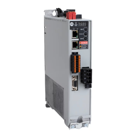
• Reserved (P1, P2, and negative DC-bus are not used) Ethernet (PORT2) RJ45 connector Motor feedback (MFB) connector Ethernet (PORT1) RJ45 connector Motor power output terminals I/O signal connector Shunt resistor terminals Auxiliary feedback (AUX) connector Rockwell Automation Publication 2198-UM004D-EN-P - December 2022... - Page 51 Kinetix 5100 Drive, Bottom View Kinetix 5100 Drive, Top View (2198-E4020-ERS drive is shown) (2198-E4020-ERS drive is shown) Kinetix 5100 Drive, Front View For feature descriptions see table on page (2198-E4020-ERS drive is shown) Rockwell Automation Publication 2198-UM004D-EN-P - December 2022...
-
Page 52: Safe Torque-Off Connector Pinout
(1) Control power terminals are labeled L1C/L2C for 2198-1xxx-ERS and 2198-2xxx-ERS (200V-class) drives and 24V+/24V- for 2198-4xxx-ERS (400V-class) drives. Safe Torque-off Connector Pinout The hardwired safe torque-off (STO) connector pinouts apply to all Kinetix 5100 servo drives. For feature descriptions and wiring information, refer to Chapter 13 beginning on page 415. Rockwell Automation Publication 2198-UM004D-EN-P - December 2022... -
Page 53: Power Connector Pinouts
DC+ and ESH. Table 18 - Motor-Power Connector Pinout Signal Description Motor power out - U phase Motor power out - V phase Motor power out - W phase Rockwell Automation Publication 2198-UM004D-EN-P - December 2022... - Page 54 (applies to only 2198-E1020-ERS, 2198-E2030-ERS, 2198-E4004-ERS, 2198-E4007-ERS, and 2198-E4015-ERS drives) External shunt connection (applies to all drives) (1) For internal shunt, keep jumper applied between DC+ and ISH (default). Remove jumper and connect external shunt between DC+ and ESH. Rockwell Automation Publication 2198-UM004D-EN-P - December 2022...
- Page 55 Buffered encoder output Ch B+ ZMOUT+ Buffered encoder output Ch Z+ Drain wire (1) The reserved pins are not present on the 2198-TBIO terminal expansion block. Figure 23 - Pin Orientation for 50-pin SCSI I/O Connector Rockwell Automation Publication 2198-UM004D-EN-P - December 2022...
-
Page 56: Auxiliary Feedback Connector Pinout
Channel B Differential Input - Reserved Reserved Channel Index Differential Input + Reserved Reserved Figure 25 - Pin Orientation for Auxiliary Feedback (AUX) Connector Front of Soldered Pins View from rear of Connector Kit connector kit. Rockwell Automation Publication 2198-UM004D-EN-P - December 2022... -
Page 57: Ethernet Communication Connector Pinout
433. If the defined digital input function needs to change to meet your application requirements, you can change the functions by using a PR Write to Parameters program type for the function of INPUT1…INPUT10 by using the corresponding parameters listed in Table Rockwell Automation Publication 2198-UM004D-EN-P - December 2022... - Page 58 NPN sinking. Figure 27 - Digital Input Circuitry Servo Drive DCOM 4.7 kΩ, approx. NPN Transistor (Source mode) 24V DC INPUTx Servo Drive INPUTx PNP Transistor (Sink mode) 24V DC 4.7 kΩ, approx. DCOM Rockwell Automation Publication 2198-UM004D-EN-P - December 2022...
- Page 59 In this example, Servo On is assigned to digital input 1 as a sinking type input. Figure 28 - Digital Input Example 2198-Exxxx-ERS Kinetix 5100 Servo Drive I/O Connector with 2198-TBIO Expansion Block +24V DC Servo On (INPUT1) 24V DC –24V COM Supply DCOM Rockwell Automation Publication 2198-UM004D-EN-P - December 2022...
-
Page 60: Digital Outputs
Table 26 - Digital Output Signal Parameters Configuration Configuration Signal Signal Parameter Parameter OUTPUT1+ OUTPUT4+ ID203 ID206 (P2.018) (P2.021) OUTPUT1- OUTPUT4- OUTPUT2+ 5 OUTPUT5+ ID204 ID207 (P2.019) (P2.022) OUTPUT2- OUTPUT5- OUTPUT3+ 3 OUTPUT6+ ID205 ID225 (P2.020) (P2.041) OUTPUT3- OUTPUT6- Rockwell Automation Publication 2198-UM004D-EN-P - December 2022... - Page 61 Interval of the digital outputs status updating in Scan time – 250 µs drive firmware Signal propagation delay from the firmware- Pass through delay – 1.0 ms accessible registers to the digital output Rockwell Automation Publication 2198-UM004D-EN-P - December 2022...
- Page 62 Relay 700-HK36Z24 with DIN mount 700-HN121 or equivalent • Choose from these suppression devices: - 1N4004 diodes or equivalent - Bulletin 199-MSMV1 MOV or equivalent Digital Outputs page 60 for the default digital output assignments for Kinetix 5100 drives. Rockwell Automation Publication 2198-UM004D-EN-P - December 2022...
-
Page 63: Analog Inputs
Pulse B+ 51 Ω 5 1 Ω Pulse B– APWR Pulse input frequency (max): 1 .5 K Ω 200 kHz 51 Ω Pulse A+ 51 Ω Pulse A– I/O Connector with 2198-TBIO Expansion Block Rockwell Automation Publication 2198-UM004D-EN-P - December 2022... - Page 64 4 MHz 51 Ω SIGN Pulse B+ 51Ω /SIGN Pulse B– Pulse input frequency (max): 4 MHz PULSE 51 Ω Pulse A+ 51 Ω /PULSE Pulse A– I/O Connector with 2198-TBIO Expansion Block Rockwell Automation Publication 2198-UM004D-EN-P - December 2022...
-
Page 65: Analog Outputs
Encoder output signals can be connected to the receiving device with line receiver (differential) or -coupler isolated inputs. The encoder output opto signals are flexible. The signals are scaled and programmed by using KNX5100C software > Function List > Pulse Output. Rockwell Automation Publication 2198-UM004D-EN-P - December 2022... - Page 66 AMOUT– High Speed Photo Coupler I/O Connector with 2198-TBIO Expansion Block 200 Ω BMOUT+ BMOUT– High Speed Photo Coupler I/O Connector with 2198-TBIO Expansion Block 200 Ω ZMOUT+ ZMOUT– High Speed Photo Coupler Rockwell Automation Publication 2198-UM004D-EN-P - December 2022...
-
Page 67: Ethernet Communication Specifications
Logix Designer application. Communication 100BASE-TX, full-duplex is recommended for maximum performance. Request Packet Interval (RPI) 2.0 ms, min (20 ms default) Auto MDI/MDIX crossover detection/ correction Cabling CAT5e shielded, 100 m (328 ft), max Rockwell Automation Publication 2198-UM004D-EN-P - December 2022... -
Page 68: Motor Brake Circuit
Relay 700-HK36Z24 with DIN mount 700-HN121 or equivalent • Suppression device examples include 1N4004 diode, Bulletin 199-MSMV1 MOV, or equivalent See Kinetix Rotary Motion Specifications Technical Data, publication KNX-TD001, for coil current ratings and brake response times. Rockwell Automation Publication 2198-UM004D-EN-P - December 2022... - Page 69 You must command the servo drive to 0 rpm and engage the brake only after verifying that the motor shaft is at 0 rpm. 7. In Brake Time Settings, enter ID149 (P1.042) Disengage Delay Time and ID150 (P1.043) Engage Delay Time parameter values. Rockwell Automation Publication 2198-UM004D-EN-P - December 2022...
- Page 70 OFF (scenario 2). If the zero speed condition is not met and the Engage Delay Time expires, the brake output is OFF (scenario 1). IMPORTANT If the ZeroSpeedWindow and Brake Delay parameters are not set correctly, the brake can set while the motor is in motion. Rockwell Automation Publication 2198-UM004D-EN-P - December 2022...
-
Page 71: Control Power
18.20 0.22 37.40 2198-E1015-ERS 0.38 19.20 0.22 39.80 2198-E1020-ERS 0.63 19.20 0.35 32.40 2198-E2030-ERS – – 0.35 36.40 2198-E2055-ERS – – 0.46 32.80 2198-E2075-ERS – – 0.48 40.0 2198-E2150-ERS – – 0.92 37.0 Rockwell Automation Publication 2198-UM004D-EN-P - December 2022... -
Page 72: Feedback Specifications
• Digital AqB with or without UVW, incremental Power supply (EPWR5V) 5.09…5.41V, 300 mA, max Power supply (EPWR9V) 8.3…9.9V, 150 mA, max Single-ended input: Motor thermostat • Under 500 Ω = No Fault • Over 10 kΩ = Fault Rockwell Automation Publication 2198-UM004D-EN-P - December 2022... -
Page 73: Motor Feedback Supported By Using The Mfb Connector
Programmed with Kinetix TLP motor data as Allen-Bradley memory Encoder nonvolatile memory usage format Differential input voltage 1.0…7.0V Data communication 8 Mbps, 21 data bits with ECC, no parity Battery type 3.6V, ER14252 or equivalent, 1/2AA size Rockwell Automation Publication 2198-UM004D-EN-P - December 2022... -
Page 74: Auxiliary Feedback Specifications
10-pin auxiliary feedback connector (AUX). See Table 38 page 74 for Digital AqB encoder feedback specifications. Table 40 - Auxiliary Feedback Signals by Device Type Digital AqB Incremental AUX_AM+ AUX_AM- AUX_BM+ AUX_BM- AUX_IM+ AUX_IM- AUX_ECOM AUX_EPWR5V Reserved Reserved Rockwell Automation Publication 2198-UM004D-EN-P - December 2022... -
Page 75: Encoder Phasing Definitions
The drive MFB connector uses Hall signals to initialize the commutation angle for permanent magnet motor commutation. Rockwell Automation Publication 2198-UM004D-EN-P - December 2022... -
Page 76: Absolute Position Feature
Figure 44 - Absolute Position Limits (measured in turns or revolutions) 65,536 Revolutions 4096 Turns 2048 Turns +4096 +32,768 -32,768 -16,384 -8192 -4096 -2048 -1024 +1024 +2048 +8192 +16,384 Position at Power Down Rockwell Automation Publication 2198-UM004D-EN-P - December 2022... -
Page 77: Safe Torque Off Feature
Switches S and T mode with DI signals. – – Reserved Position mode PT (I/O terminal block input) and Position mode PR (register PT-PR Switches PT and PR Mode with DI signals. input) Rockwell Automation Publication 2198-UM004D-EN-P - December 2022... - Page 78 Switches PT, PR, and S mode with DI signals. input), and Speed mode Position mode PT (I/O terminal block input), Position mode PR (register PT-PR-T Switches PT, PR, and T mode with DI signals. input), and Torque mode Rockwell Automation Publication 2198-UM004D-EN-P - December 2022...
-
Page 79: Connect The Kinetix 5100 Drive System
National Electrical Code, local electrical codes, special operating temperatures, duty cycles, or system configurations take precedence over the values and methods provided. Rockwell Automation Publication 2198-UM004D-EN-P - December 2022... -
Page 80: Build Your Own Cables
For Kinetix 5100 drive power specifications, see Kinetix Servo Drives Specifications Technical Data, publication KNX-TD003. For Kinetix 5100 drive input-wiring diagrams, see Power Wiring Examples page 458. Rockwell Automation Publication 2198-UM004D-EN-P - December 2022... -
Page 81: Three-Phase Power Wired To Three-Phase Drives
Transformer (wye) Secondary AC Line Mains AC Input Feeder and branch short-circuit Filter Power Connector protection is not illustrated. Circuit Protection 2198-Exxxx-ERS Servo Drives Bonded Cabinet Ground Bus Ground Grid or Power Distribution Ground Rockwell Automation Publication 2198-UM004D-EN-P - December 2022... -
Page 82: Single-Phase Input Power Used With Single-Phase Drives
Mains AC Input AC Line 230V AC Power Connector Filter Output Circuit L1 (Neutral) Protection 2198-E1004-ERS, 2198-E1007-ERS, 2198-E1015-ERS, and 2198-E1020-ERS Drives with Single-phase Operation Bonded Cabinet Ground Bus Ground Grid or Power Distribution Ground Rockwell Automation Publication 2198-UM004D-EN-P - December 2022... -
Page 83: Three-Phase Input Power Used With Single-Phase Drives
Kinetix 5100 Drives AC Line Circuit (System C) Filter Protection Single-phase AC Input Grounded 2198-E1004-ERS, 2198-E1007-ERS, Neutral 2198-E1015-ERS, and 2198-E1020-ERS Bonded Cabinet Ground Bus Drives with Single-phase Operation Ground Grid or Power Distribution Ground Rockwell Automation Publication 2198-UM004D-EN-P - December 2022... -
Page 84: Voiding Of Ce And Uk Compliance
EMC and aspect for CE and UK compliance. Therefore, EMC validity and CE and UKCA marking by Rockwell Automation is voided when three-phase and neutral in-line filters are used. ATTENTION: The three-phase isolation transformers with neutral in-line... -
Page 85: Ground The Drive System
Braided ground strap (customer supplied) Ground grid or power distribution ground Bonded cabinet ground bus (customer supplied) Refer to the System Design for Control of Electrical Noise Reference Manual, publication GMC-RM001, for more information. Rockwell Automation Publication 2198-UM004D-EN-P - December 2022... -
Page 86: Ground Multiple Subpanels
Appendix A beginning on page 457 for interconnect diagrams. IMPORTANT The National Electrical Code and local electrical codes take precedence over the values and methods provided. Rockwell Automation Publication 2198-UM004D-EN-P - December 2022... - Page 87 (4) Motor power wire size depends on drive and motor combination. See Kinetix 5100 Drive Systems Design Guide, publication KNX-RM011, for specific drive and motor combination. (5) Attach using a terminal crimp lug. Rockwell Automation Publication 2198-UM004D-EN-P - December 2022...
-
Page 88: Wiring Guidelines
2198-E4150-ERS (400V) drives to the specified torque value. - Connectors on 2198-E1004-ERS, 2198-E1007-ERS, 2198-E1015-ERS, 2198-E1020-ERS, and 2198-E2030-ERS (200V) drives and 2198-E4004-ERS, 2198-E4007-ERS, 2198-E4015-ERS (400V) drives use spring tension to hold wires in place. Rockwell Automation Publication 2198-UM004D-EN-P - December 2022... -
Page 89: Wire The Input Power Connectors
Front View CHARGE Mains Input Power Connections DC– Reserved DC– (not used) DC– 2198-E1020-ERS and 2198- E2030-ERS 2198-E2055-ERS, 2198-E2075-ERS, and 2198-E2150-ERS Kinetix 5100 Servo Drives Kinetix 5100 Servo Drives Front View Front View Rockwell Automation Publication 2198-UM004D-EN-P - December 2022... - Page 90 2198-E4030-ERS 0.82…8.36 24V- 2198-E4055-ERS (18…8) (13.90) 2198-E4075-ERS 11 (0.4) 2.08…21.1 2198-E4150-ERS 13 (0.5) (14…4) (27.44) (1) This connector uses spring tension to hold wires in place. (2) Attach using a terminal crimp lug. Rockwell Automation Publication 2198-UM004D-EN-P - December 2022...
-
Page 91: Wire The I/O Connector
Figure 59 - 2198-E1004-ERS, 2198-E1007-ERS and 2198-E1015-ERS Servo Drives Kinetix 5100 Servo Drives (2198-E1004-ERS drive is shown) Bottom View Motor Power Connector Rockwell Automation Publication 2198-UM004D-EN-P - December 2022... - Page 92 (13.90) 2198-E4055-ERS 2198-E4075-ERS 2.08…21.1 2198-E4150-ERS (14…4) (27.44) (1) Motor power cable depends on motor/drive combination. (2) This connector uses spring tension to hold wires in place. (3) Attach using a terminal crimp lug. Rockwell Automation Publication 2198-UM004D-EN-P - December 2022...
-
Page 93: Servo Motor And Motor Cable Compatibility
Logix Designer Application Version Kinetix 5100 AOP Needed? 30, 31, or 32 1.xxx or 2.xxx 33.00 or later Install the Kinetix 5100 Add-On Profile on page 190 for information on downloading the AOP. Rockwell Automation Publication 2198-UM004D-EN-P - December 2022... -
Page 94: Motor Power And Brake Cables
MPAI-A/Bxxxx, MPAR-A/B3xxx, MPAR-A/B1xxx and MPAR-A/B2xxx (series B) MPAS-Bxxxxx-ALMx2C LDAT-Sxxxxxx-xBx (these devices do not include a brake option) LDC-Cxxxxxx LDL-xxxxxxx (1) Refer to the Kinetix Motion Accessories Specifications Technical Data, publication KNX-TD004, for cable specifications. Rockwell Automation Publication 2198-UM004D-EN-P - December 2022... -
Page 95: Maximum Cable Length
Incremental MPL-A3xxx-Hx7xAA MPL-A4xxx-Hx7xAA MPL-A45xxx-Hx7xAA 30 (98.4) MPAS-Axxxx-ALMx2C (direct drive) Incremental, magnetic linear TLY-Axxxx-B Tamagawa (17-bit) absolute high-resolution, multi-turn TL-Axxxx-B TLY-Axxxx-H Incremental LDAT-Sxxxxxx-xBx Incremental, magnetic scale 10 (33.1) LDC-Cxxxxxx-xH, LDL-xxxxxxx-xH Sin/Cos or TTL encoder Rockwell Automation Publication 2198-UM004D-EN-P - December 2022... -
Page 96: Cable Preparation For Kinetix Tlp Servo Motors
Cables Installation Instructions, publication 2090-IN048, to attach motor-side power and feedback connector kits to bulk cable. Also, see Kinetix 5100 Feedback Connector Kit Installation Instructions, publication 2198-IN019, to terminate the flying lead feedback cable connections. Rockwell Automation Publication 2198-UM004D-EN-P - December 2022... -
Page 97: Cable Preparation For Kinetix Mp Servo Motors
See Build Your Own Kinetix TLP Motor Cables Installation Instructions, publication 2090-IN048, to attach the proper ring lugs to PE, U, V, and W conductors to 2090-CPBM7DF power cables when used with 2198-E2055-ERS, 2198-E2075-ERS, 2198-E2150-ERS, and 2198-4xxx-ERS servo drives. Rockwell Automation Publication 2198-UM004D-EN-P - December 2022... -
Page 98: Cable Preparation For Kinetix Tl And Tly Motor Power Cables
2090-IN048, to attach the proper ring lugs to PE, U, V, and W conductors to 2090-CPBM7DF power cables. SHOCK HAZARD: To avoid hazard of electrical shock, make sure shielded power cables are grounded according to recommendations. Rockwell Automation Publication 2198-UM004D-EN-P - December 2022... - Page 99 Figure 64 - Kinetix 5100 Drive Ground Plate Examples 2198-E1020-ERS 2198-E2055-ERS 2198-E2150-ERS 2198-E2075-ERS 2198-E2030-ERS 2198-E4055-ERS 2198-E4150-ERS 2198-E4075-ERS 2198-E1004-ERS 2198-E4004-ERS 2198-E1007-ERS 2198-E4020-ERS 2198-E4007-ERS 2198-E1015-ERS 2198-E4015-ERS 2198-E4030-ERS Rockwell Automation Publication 2198-UM004D-EN-P - December 2022...
-
Page 100: Motor Brake Connections
2090-CTFB-MADD-CFAxx (standard) or TLP-A046-xxx, TLP-A/B070-xxx, TLP-A/B090-xxx, TLP-A100-xxx 2090-CTFB-MADD-CFFxx (continuous-flex) 2090-CTFB-MFDD-CFAxx (standard) or TLP-A/B115-xxx, TLP-A/B145-xxx, TLP-A/B200-xxx, TLP-A/B235-xxx 2090-CTFB-MFDD-CFFxx (continuous-flex) (1) Refer to the Kinetix Motion Accessories Specifications Technical Data, publication KNX-TD004, for cable specifications. Rockwell Automation Publication 2198-UM004D-EN-P - December 2022... -
Page 101: Cable Preparation For Kinetix Tlp Feedback Cables
Cables Installation Instructions, publication 2090-IN048, and make flying-lead feedback connections to the 2198-K51CK-D15M connector kit. Figure 65 - Battery Box Wired With Battery Battery Battery backup wires inserted in terminals. Feedback Cable Battery Box (cover removed) Rockwell Automation Publication 2198-UM004D-EN-P - December 2022... -
Page 102: Cable Preparation For 2090-Cfbm7Dx Feedback Cables
Kinetix 5100 Servo Drive (front view) 5100 CHARGE DC– 2198-K51CK-D15M Feedback Connector Kit (battery backup is optional) 2090-DANFCT-Sxx 2090-DANPT-16Sxx Motor Feedback Cable Motor Power Cable (drive-end connector removed) Kinetix TL (TL-Axxxx-B) Servo Motors (high-resolution encoder) Rockwell Automation Publication 2198-UM004D-EN-P - December 2022... -
Page 103: Motor Feedback Cable Preparation
2. Determine the length for each wire and trim as necessary. 3. Remove 5.0 mm (0.2 in.) of insulation from the end of each wire. Dimensions are in mm (in.) 5.0 (0.2) Cable Shield Cable Jacket 120 (4.7) 7.0 (0.3) 127 (5.0) Rockwell Automation Publication 2198-UM004D-EN-P - December 2022... - Page 104 Refer to the connector pinout as shown in Figure 67 page 107. 4. Attach the tie-wrap (customer-supplied) through the slots and around the cable shield for stress relief and to create a high-frequency bond between shield and ground pad. Rockwell Automation Publication 2198-UM004D-EN-P - December 2022...
-
Page 105: Kinetix 2090 Feedback Cable Pinouts
Table 62 - 2090-CTFB-MxDD-CFxxx Feedback Cables TLP-Axxx-xxx and TLP-Bxxx-xxx 2198-K51CK-D15M Motor Pin 24-bit Absolute, Multi-turn/Single-turn Wire Color Connector Kit Pin High-resolution White T– White/Red BAT+ Pin + BAT– Black Pin – Drain – ECOM Blue EPWR_5V Brown Rockwell Automation Publication 2198-UM004D-EN-P - December 2022... - Page 106 17-bit Absolute, Multi-turn, High-resolution Feedback Connector Kit Pin DATA+ Green DATA– White/Green 10 EPWR_5V Gray ECOM and BAT- White/Gray BAT+ Orange BAT+ Drain – (1) BAT- is tied to ECOM (pin 23) in the cable. Rockwell Automation Publication 2198-UM004D-EN-P - December 2022...
- Page 107 Exposed Shield Aligned Stress Relief and Under the Shield Clamp Wire Management (1) The ECOM and TS- connections are tied together and connect to the cable shield. (2) See cable pinouts for wire colors. Rockwell Automation Publication 2198-UM004D-EN-P - December 2022...
-
Page 108: External Passive-Shunt Resistor Connections
Front View CHARGE DC– Shunt Connections 2198-E1020-ERS, 2198-E2055-ERS, 2198-E2075-ERS, 2198-E2030-ERS, 2198-E2150-ERS, 2198-E4020-ERS, 2198-E4004-ERS, 2198-E4030-ERS, 2198-E4055-ERS, 2198-E4007-ERS, and 2198-E4075-ERS, and 2198-E4150-ERS 2198-E4015-ERS Kinetix 5100 Servo Drives Kinetix 5100 Servo Drives Front View Front View Rockwell Automation Publication 2198-UM004D-EN-P - December 2022... - Page 109 (27.44) (1) This connector uses spring tension to hold wires in place. (2) Attach using a terminal crimp lug. Passive Shunt Considerations page 35 for shunts compatible with your Kinetix 5100 servo drive. Rockwell Automation Publication 2198-UM004D-EN-P - December 2022...
-
Page 110: Ethernet Cable Connections
1 GB Ethernet Port Port 2, Rear Bottom View The Logix 5000 controllers accept linear, ring (DLR), and star network configurations. Refer to Typical Communication Configurations page 21 for linear, ring, and star configuration examples. Rockwell Automation Publication 2198-UM004D-EN-P - December 2022... - Page 111 BOOTP-DHCP tool on page 115 The drive is factory programmed to static IP address of 192.168.1.1 and Gateway address of 192.168.1.254. IMPORTANT Only standalone mode is supported for linear motors and induction motors. Rockwell Automation Publication 2198-UM004D-EN-P - December 2022...
-
Page 112: Set Up Ethernet/Ip Communication
2. In the Device Information screen or Drive Status screen, the current IP address is shown. 3. Press key. SETTING appears on the display. 4. Press key. NET SETTING scrolls across the display. 5. Press key. STATIC IP scrolls across the display. Rockwell Automation Publication 2198-UM004D-EN-P - December 2022... - Page 113 The display toggles between OFF and ON. To apply the setting, press key or to exit the setting press keypad. Chapter Use the Keypad Interface for help with setting the network parameters Rockwell Automation Publication 2198-UM004D-EN-P - December 2022...
-
Page 114: Set Network Parameters By Using Knx5100C Software
3. If STATIC IP, then configure the following parameters: - IP address - Gateway - Subnet mask 4. Click Apply. 5. To have the IP Settings take effect, click Reset Module from the tool bar. Rockwell Automation Publication 2198-UM004D-EN-P - December 2022... -
Page 115: Configure Ip Address By Using Bootp-Dhcp Tool
DHCP on the network, and displays the device MAC addresses as shown. You can find the MAC address of your drive on the drive label. In this example, the MAC address 00:00:BC:01:01:01 is used. Rockwell Automation Publication 2198-UM004D-EN-P - December 2022... - Page 116 Set Up EtherNet/IP Communication 3. From the dialog box, double-click the MAC address of your drive. The New Entry dialog appears. 4. Type your specified IP address in the New Entry dialog, and then click Rockwell Automation Publication 2198-UM004D-EN-P - December 2022...
-
Page 117: Use The Keypad Interface
Use this key to toggle between the digits or menus in the same level. Use this key to enter a sub-menu, if one exists, or to confirm a value Set key that you have edited. Rockwell Automation Publication 2198-UM004D-EN-P - December 2022... -
Page 118: Drive Displays
Drive Status screen to view information. If no button is pressed and no fault or alarm occurs within one minute, then the display reverts back to Real Time Data. Rockwell Automation Publication 2198-UM004D-EN-P - December 2022... - Page 119 Input pulse number of pulse command before the Count scaling of electronic gear ratio. (encoder unit) Error pulse number after the scaling of electronic Count gear ratio. (encoder unit) Input frequency of pulse command. Motor speed. Speed command. Volt Rockwell Automation Publication 2198-UM004D-EN-P - December 2022...
- Page 120 Offset value between motor position and Z phase in PUU unit. The value is 0 when the position overlaps User Unit with Z phase. The greater the value, the greater the offset. Current drive fault. — Rockwell Automation Publication 2198-UM004D-EN-P - December 2022...
-
Page 121: Drive Status Display
When the drive is disabled/servo off, the Setting screen lets you edit the network address or drive parameters, or reset the drive. For more information, see Edit Settings From the Display on page 122. Rockwell Automation Publication 2198-UM004D-EN-P - December 2022... -
Page 122: Edit Settings From The Display
Figure 4. Press in any one of those settings displays and use the keys to edit the values. 5. Press the key twice to set the values and return to the original display. Rockwell Automation Publication 2198-UM004D-EN-P - December 2022... - Page 123 OFF or ON. 3. Press the key to return to the DHCP editing display. 4. Press the key to return to the IP Setting display. Network Setting Static IP Setting DHCP ON/OFF Rockwell Automation Publication 2198-UM004D-EN-P - December 2022...
-
Page 124: Edit Parameter Settings
See Table 69 on page 125. Network Setting Setting Parameter Parameter Mode Confirm Parameter Group 0 Parameter Group 0 Change Value Change Digits Parameter Parameter Cancel Parameter Parameter Parameter Parameter Rockwell Automation Publication 2198-UM004D-EN-P - December 2022... -
Page 125: Reset The Drive Via Keypad
To reset the drive, perform the following steps. 1. From the Parameter display, press the key to get to the Reset display. 2. On the Reset display, press the key. The reset string blinks. 3. Press the key again. Rockwell Automation Publication 2198-UM004D-EN-P - December 2022... -
Page 126: Display Low Byte, High Byte, And Negative Values
L0000 in hexadecimal format. (Hex low) Figure 76 shows the panel display of positive and negative signs. Figure 76 - Panel Display Positive Sign Negative Sign Rockwell Automation Publication 2198-UM004D-EN-P - December 2022... -
Page 127: Display Fault Record
You can use the keypad to display the status of digital inputs and outputs. Digital Input Diagnosis Operation When external output signal triggers DI1…DI10, the display shows the corresponding signal by bit. When the bit is equal to 1, the DI is on. Rockwell Automation Publication 2198-UM004D-EN-P - December 2022... -
Page 128: Display Firmware Upgrade Information
F is 1111, then DO1…DO4 are on. Binary code 0 0 0 1 1 1 1 1 Corresponding DI status The display is in hexadecimal format. Display Firmware Upgrade Information Upgrade Kinetix 5100 Drive Firmware on page 477. Rockwell Automation Publication 2198-UM004D-EN-P - December 2022... -
Page 129: Configure The Drive With Knx5100C Software
Kinetix 5100 drive. These procedures assume that you have wired your Kinetix 5100 drive system. KNX5100C software is required for all applications. It is used to commission, configure, and possibly program the Kinetix 5100 drive. Rockwell Automation Publication 2198-UM004D-EN-P - December 2022... -
Page 130: Download Knx5100C Software
Launch KNX5100C Configuration Tool To launch the KNX5100C configuration tool, perform the following steps. 1. Use one of two methods to launch the KNX5100C software: a. On your personal computer desktop, double-click the KNX5100C shortcut icon. Rockwell Automation Publication 2198-UM004D-EN-P - December 2022... - Page 131 If you are connected to your drive, click the Com port pull-down menu and select a COM port. In some cases, the mini-USB cable has to be removed and reinserted to refresh the COM port state. Rockwell Automation Publication 2198-UM004D-EN-P - December 2022...
-
Page 132: Connect To The Drive/Set Your Com Port
1. From the Function List, click Communication Setting. 2. Choose the COM port associated with your drive. You can choose the COM port from the pull-down menu, or click to refresh the COM port. Rockwell Automation Publication 2198-UM004D-EN-P - December 2022... - Page 133 OK. 5. If you select the first option, an uploading message box appears until the process is completed. 6. In the Communication Setting dialog, communication status is shown as online. Rockwell Automation Publication 2198-UM004D-EN-P - December 2022...
-
Page 134: Configure Drive Settings
Configure the Motor In the KNX5100C software, navigate to Function List > Settings > Selection in KNX5100C Motor Selection. There are three data sources available to configure the motor/ Software actuator through the Function List. Rockwell Automation Publication 2198-UM004D-EN-P - December 2022... -
Page 135: Data Source
Motor NV on page 136. When the data source is Catalog Number and a Kinetix LDC or Kinetix LDL motor is selected, you must manually enter the parameters in the Motor Feedback dialog box. Rockwell Automation Publication 2198-UM004D-EN-P - December 2022... - Page 136 Motor Device Specification dialog box except for the Motor Overload Limit field and the Next button. 1. Type an appropriate Motor Overload Limit and click Next. 2. On the Motor Model Phase screen, click Next. Rockwell Automation Publication 2198-UM004D-EN-P - December 2022...
- Page 137 Automatically triggers a drive reset and power cycle After the reset and power cycle, the identified motor catalog number is shown in the motor page, and the motor related parameters are updated according to encoder internal memory. Rockwell Automation Publication 2198-UM004D-EN-P - December 2022...
- Page 138 IMPORTANT If the startup method is Absolute and the TLP motor is configured, a battery must be used to establish absolute positioning; regardless of single or multi-turn operation. See Table 36 on page 73 for battery specifications. Rockwell Automation Publication 2198-UM004D-EN-P - December 2022...
- Page 139 Change Catalog Number dialog box. To change the catalog number, perform the following steps. 1. Choose Function List > Settings > Motor Selection, and select Catalog Number from the Data Source pull-down menu. 2. Click Change Catalog… Rockwell Automation Publication 2198-UM004D-EN-P - December 2022...
- Page 140 If your motor has an intelligent encoder and you select the wrong catalog IMPORTANT number, an E 60A (Catalog Number Match Error) fault occurs at the drive. Rockwell Automation Publication 2198-UM004D-EN-P - December 2022...
- Page 141 2. After you add data manually to the fields under the Nameplate/ Datasheet-Phase to Phase Parameters section, click Next. 3. From the Motor Model Phase to Neutral Parameters dialog box, add data manually. When you are done, click Next. Rockwell Automation Publication 2198-UM004D-EN-P - December 2022...
- Page 142 1. Select Motor > Analyzer. 2. Click Start to initiate the analyze process. 3. After each step of the analyzing process is completed, a confirmation window appears; click OK. A results window appears with suggested parameter values. Rockwell Automation Publication 2198-UM004D-EN-P - December 2022...
- Page 143 A results window appears with suggested parameter values. 4. Click Accept if you want to use those values, or click Cancel if you want to stay with the parameters that you added manually. Rockwell Automation Publication 2198-UM004D-EN-P - December 2022...
- Page 144 A results window appears with suggested parameter values. 4. Click Accept if you want to use those values, or click Cancel if you want to stay with the parameters that you added manually. Rockwell Automation Publication 2198-UM004D-EN-P - December 2022...
- Page 145 2. Select Inertia Estimation and click Start to initiate the analysis. A confirmation dialog box displays. 3. Click Yes and a dialog box appears indicating that the drive will perform servo-on to execute dynamic analysis. A results window appears with suggested parameter values. Rockwell Automation Publication 2198-UM004D-EN-P - December 2022...
-
Page 146: Selection Of Motor Thermal Models
1st order filter, with a 20 minute time constant, to the output current. The hot curve corresponds to a filtered output current of 100% or greater rated current. The cold curve corresponds to a filter output current of 0%. Rockwell Automation Publication 2198-UM004D-EN-P - December 2022... - Page 147 MotorThermalOverloadUserLimit values for this thermal model are both 110%. IMPORTANT This thermal model does not derate the motor-rated current when operating at low speeds. Operating at low output frequencies does not cause the MotorCapacity behavior to change. Rockwell Automation Publication 2198-UM004D-EN-P - December 2022...
-
Page 148: Motor Feedback
For others, the selection can be changed. IMPORTANT If you select Digital AqB when the attached motor has a Hall sensor, the drive ignores the Hall sensor. Figure 78 - Supported Motor Feedback Rockwell Automation Publication 2198-UM004D-EN-P - December 2022... - Page 149 If you select Drive Offset as the Commutation Alignment type, the valid range of the Commutation Offset is calculated based on the Commutation Offset from the encoder’s internal value (x): x-85 < Commutation Offset setting < x+85 (unit: degree) Rockwell Automation Publication 2198-UM004D-EN-P - December 2022...
-
Page 150: Run A Commutation Test
ATTENTION: To avoid personal injury or damage to equipment, you must uncouple the motor from each load you test as uncontrolled motion can occur if an axis with an integral motor brake is released during the test. Rockwell Automation Publication 2198-UM004D-EN-P - December 2022... - Page 151 6. Click Yes. A message window alerts you that the process might take some time to complete. When the process is complete, a results window appears with suggested parameter values. Rockwell Automation Publication 2198-UM004D-EN-P - December 2022...
-
Page 152: Parameter Editor
(page 154), and a status indicator that includes the firmware version and other information. To access the Parameter Editor, select Start > Kinetix 5100 > Setting > Parameter Editor in the Function List. Rockwell Automation Publication 2198-UM004D-EN-P - December 2022... - Page 153 (S) Value is set when servo power is off • (P) Value is applied after a Power Cycle • (V) Value is volatile (cleared once power is cycled) The firmware version is also shown in this window. Rockwell Automation Publication 2198-UM004D-EN-P - December 2022...
-
Page 154: Parameter Wizard
When online with the Kinetix 5100 drive, a dialog box lets you choose to download all the parameters or just the parameters that have been modified. Stop Operation This stops any operation in progress. Rockwell Automation Publication 2198-UM004D-EN-P - December 2022... - Page 155 Use this function to compare the file you open with existing parameters. n your personal computer, navigate to your target saved *.par file. 2. Select the file and click Open. A message appears that the comparison process has started. Rockwell Automation Publication 2198-UM004D-EN-P - December 2022...
-
Page 156: Choose An Operation Mode
If you click No, you are returned to the Settings view without a power cycle. However, a reminder appears until you initiate a power cycle. IMPORTANT ControlMode Parameter ID117 (P1.001) is valid only after power cycle. Rockwell Automation Publication 2198-UM004D-EN-P - December 2022... -
Page 157: Using The Setting Page
If you click No, the original operation mode is used. Using the Parameter Editor To change the control mode in the Parameter Editor, perform the following steps. 1. From Function List, select Start > Kinetix 5100 > Setting > Parameter Editor. Rockwell Automation Publication 2198-UM004D-EN-P - December 2022... - Page 158 The drive is polled immediately and updates the Value field. 3. In KNX5100C software, choose the Operation Mode from the main screen pull-down menu. After the parameter value is changed, the following reminder appears. Rockwell Automation Publication 2198-UM004D-EN-P - December 2022...
-
Page 159: Configure Settings
From the Settings selection, you can view and change the operation mode. The Operation Mode control loop diagram is updated based on the mode. When the Operation Mode value is changed from the pull-down menu, subsequent pull-down menus can appear. Rockwell Automation Publication 2198-UM004D-EN-P - December 2022... -
Page 160: Configure General Settings
2. In General Settings, change the fields manually as needed. Any changes to these settings require the motor to be disabled. 3. Click Download to send any changed parameters to the servo drive. Rockwell Automation Publication 2198-UM004D-EN-P - December 2022... - Page 161 • Requires an enabling signal (second input is used to enable the motor). [0x47] Profile Quick Stop • Uses a programmable deceleration profile AutoProtectionDecelTime ID296 (P5.003). • Alarm is issued at the end of the disable operation. Rockwell Automation Publication 2198-UM004D-EN-P - December 2022...
- Page 162 Servo on with Holding Brake and make this a NO type of input. 6. Verify that the motor holding brake has been selected; if it is not selected, use the pull-down menu and associate a DO as Brake Control. Rockwell Automation Publication 2198-UM004D-EN-P - December 2022...
- Page 163 Chapter 7 Configure the Drive with KNX5100C Software Rockwell Automation Publication 2198-UM004D-EN-P - December 2022...
-
Page 164: Configure The Command Source
If you have configured a dual or multiple operation mode, more than one tab is visible. For example, if you have PT/S mode, you get a Position mode (I/O terminal block input) tab and a Speed mode tab. Rockwell Automation Publication 2198-UM004D-EN-P - December 2022... - Page 165 The Speed Mode tab is visible if you have configured a dual or IMPORTANT multiple operation mode, such as PT/S mode. 1. From the Function List, choose Start>Kinetix 5100> Setting and select the Operating Mode as S:Speed Control Mode. 2. Click the Speed Command box. Rockwell Automation Publication 2198-UM004D-EN-P - December 2022...
- Page 166 The Torque Mode tab is visible if you have configured a dual or IMPORTANT multiple operating mode. 1. From the Function List, choose Start>Kinetix 5100>Setting and select the Operating Mode as T:Torque Control Mode. 2. Click the Torque Command box. Rockwell Automation Publication 2198-UM004D-EN-P - December 2022...
- Page 167 DI.TCM0 and DI.TCM1. You can change the values of the torque registers 1…3 by using ID128…ID130 (P1.012…P1.014). For more information, see Selection of Torque Command on page 252. Rockwell Automation Publication 2198-UM004D-EN-P - December 2022...
-
Page 168: Configure The Pulse Outputs
3. You can also use the Settings>Parameter Editor>General to manually change the Encoder Output Resolution ID153 (P1.046), which is counts. 4. Click Download to send any changes to the servo drive. Rockwell Automation Publication 2198-UM004D-EN-P - December 2022... -
Page 169: Configure Electronic Gear (E-Gear) Ratio
GearRatioFollowerCounts N3 - ID237 (P2.061) Pulse Time Constant GearRatioFollowerCounts N4 - ID238 (P2.062) Numerators ID170 (P1.068) GearRatioMasterCounts - ID152 (P1.045) Denominator Position Command Low Pass Filter Time Constant ID124 (P1.008) Pulse Error Feedback Pulse Rockwell Automation Publication 2198-UM004D-EN-P - December 2022... - Page 170 Gear Ratio value. The Gear Ratio Selection (1) and GNUM0/1 (4) are not used in IO mode. They are used in PT Mode to select different gear ratios. Rockwell Automation Publication 2198-UM004D-EN-P - December 2022...
- Page 171 Master source input and is used to define your overall gearing relationship. So, this Master counts value is used to define the effective 'ratio' of your gearing relationship. Rockwell Automation Publication 2198-UM004D-EN-P - December 2022...
- Page 172 Opr_AOI), your position scaling changes. When you keep a 'fixed' gearing ratio, then the positioning is maintained because the E- Gear ratio values did not change. The drive follows pulses based on the present value of the E-Gear ratio. Rockwell Automation Publication 2198-UM004D-EN-P - December 2022...
- Page 173 Moving Distance per 1 Pulse Command µm 3000 3000 µm E-Gear is not applied (Unit: pulse pulse 16777216 16777216 µm 3000 16777216 µm 16777216 E-Gear is applied 1 (Unit: pulse pulse 3000 3000 16777216 Rockwell Automation Publication 2198-UM004D-EN-P - December 2022...
-
Page 174: Configure Filter
Command Smoothing Constant (ID122(P1.006) and ID123(P1.007)) except the units are ms and not 10 ms. • The Moving Average Filter time constant parameters for Position Command ID170 (P1.068), and Speed Command ID164 (P1.059). Rockwell Automation Publication 2198-UM004D-EN-P - December 2022... - Page 175 Filters available for Position Mode, Speed Mode, and Torque Mode are described in Filter on page 256 Chapter Modes of Operation. 3. Click Download to send any changes to the servo drive. Rockwell Automation Publication 2198-UM004D-EN-P - December 2022...
-
Page 176: Configure Notch Filter
You can use the System Analysis tool to diagnose the frequency of resonance. 3. Click Download to send any changes to the servo drive. For more information, see Resonance Suppression (Notch Filter, Speed Mode) on page 259. Rockwell Automation Publication 2198-UM004D-EN-P - December 2022... -
Page 177: Configure Limits
Function List>Motion Control>PR Mode Editor>Deceleration Time for Auto-protection ID296 (P5.003) Click Download to send any changes to the servo drive. For more information, see Analog Outputs and Monitoring on page 282. Rockwell Automation Publication 2198-UM004D-EN-P - December 2022... -
Page 178: Configure Analog I/O
In the Analog I/O dialog box, there are two tabs: Command Input and Output Monitor. On the Command Input tab, you can configure three types of analog input: position mode (I/O terminal block input), speed input, and torque input. Rockwell Automation Publication 2198-UM004D-EN-P - December 2022... - Page 179 The volts/rev is scaled using this formula. On this tab, you can enable the analog position function, set the initial position of the motor, and the maximum motor position value (in motor rotations). Rockwell Automation Publication 2198-UM004D-EN-P - December 2022...
- Page 180 % is scaled by using this formula. For example, if a ControlLogix 1756-M02AE module was configured for Torque mode, its analog output could be used with this torque input for the Kinetix 5100 drive to provide full closed- loop control. Rockwell Automation Publication 2198-UM004D-EN-P - December 2022...
- Page 181 Motor Speed) with your desired Analog Voltage at that speed. Click Calculate to determine the corresponding Maximum values and analog scaling ID120 (P1.004). For more information, see Analog Outputs and Monitoring on page 282. Rockwell Automation Publication 2198-UM004D-EN-P - December 2022...
-
Page 182: Configure Position, Velocity, And Current Loops
Table 73 - Position Loop Parameters Parameter Name PositionProportionalGain ID185 (P2.000) VelocityFeedforwardGain ID187 (P2.002) VelocityFeedforwardLowPassFilterTimeConstant ID188 (P2.003) PositionIntegralGain ID235 (P2.053) Click Download to download any changed parameters to the servo drive. Rockwell Automation Publication 2198-UM004D-EN-P - December 2022... -
Page 183: Configure Velocity Loop
Table 74 - Velocity Loop Parameters Parameter Name VelocityProportionalGain ID189 (P2.004) VelocityIntegralGain ID191 (P2.006) ID192 (P2.007) AccelerationFeedforwardGain VelocityFeedforwardLowPassFilterTimeConstant ID232 (P2.049) LoadInertiaRatio ID144 (P1.037) Click Download to write any changed parameters to the servo drive. Rockwell Automation Publication 2198-UM004D-EN-P - December 2022... -
Page 184: Configure Current Loop
I/O function and to see the status of digital inputs (DI) and digital outputs (DO), or to control the I/O signals manually. There are three sections in the dialog box: Digital Input (DI), Digital Output (DO), and Jog Control. Rockwell Automation Publication 2198-UM004D-EN-P - December 2022... -
Page 185: Configuration And Status Of Digital Input (Di) And Digital Output (Do) Signals
This dialog box also shows the On/Off status of the DI or DO signals and offers manual control of the DI or DO signal state. This control is useful when testing or troubleshooting the signals. Rockwell Automation Publication 2198-UM004D-EN-P - December 2022... - Page 186 5. Check Enable DO Override so that On/Off is visible. 6. Click On/Off to change the status of the DO signals directly. You can see the signal status by looking at the Status window. Rockwell Automation Publication 2198-UM004D-EN-P - December 2022...
-
Page 187: Edit Dio Configurations
2. Use the pull-down menu to change the DIO function in the drive. 3. Click OK to save the changes and write to the drive. 4. When you have configured all your I/O, clear the Edit DIO Configurations checkbox. Rockwell Automation Publication 2198-UM004D-EN-P - December 2022... -
Page 188: Jog Function
Stop clicking the left and right arrows to stop the motor rotation. c. If the observed rotation is opposite to what is desired, check Invert Direction. The direction of the jog command is inverted. Rockwell Automation Publication 2198-UM004D-EN-P - December 2022... -
Page 189: Configure The Drive In Studio 5000 Logix Designer Application
Kinetix 5100 drive Add-on Profile. Table 75 shows whether the AOP must be downloaded and installed. In later versions of Logix Designer application, the AOP is already installed. Rockwell Automation Publication 2198-UM004D-EN-P - December 2022... -
Page 190: Install The Kinetix 5100 Add-On Profile
To use your Kinetix 5100 servo drive with the provided AOP and pre- IMPORTANT defined Add-On Instructions, you must configure your Kinetix 5100 drive in KNX5100C software first and change the control mode to IO Mode. See Download KNX5100C Software on page 130. Rockwell Automation Publication 2198-UM004D-EN-P - December 2022... - Page 191 ControlLogix 5570 Controller 4. From the Revision pull-down menu, choose your software revision. 5. Click Finish. The new controller appears in the Controller Organizer under the I/O Configuration folder. CompactLogix 5370 Controller ControlLogix 5570 Controller Rockwell Automation Publication 2198-UM004D-EN-P - December 2022...
- Page 192 7. By using the filters, check Communication and Allen-Bradley, and select 1756-EN2T, 1756-EN2TR, or 1756-EN3TR as appropriate for your hardware configuration. In this example, the 1756-EN2T module is selected. 8. Click Create. The New Module dialog box appears. Rockwell Automation Publication 2198-UM004D-EN-P - December 2022...
- Page 193 11. When prompted to confirm your module definition changes, click Yes. 12. To close the New Module dialog box, click OK. Your new 1756-ENxT Ethernet module appears under the I/O Configuration folder in the Controller Organizer. 13. Click OK. Rockwell Automation Publication 2198-UM004D-EN-P - December 2022...
-
Page 194: Configure The Kinetix 5100 Drive Modules
The Select Module Type dialog box appears. 2. By using the filters, check Motion and Allen-Bradley, and select your 2198-Exxxx-ERS drive as appropriate for your hardware configuration. 3. Click Create. The New Module dialog box appears. Rockwell Automation Publication 2198-UM004D-EN-P - December 2022... - Page 195 From the Connection pull-down menu, choose the Connection mode for your motion application. IMPORTANT For new applications, it is typical to use Data with Camming. For legacy applications, use the following guidance to choose Data or Data with Camming. Rockwell Automation Publication 2198-UM004D-EN-P - December 2022...
-
Page 196: Support Automatic Device Configuration (Adc) In Aop Version 2 And Later
Ethernet network in the I/O Configuration folder. CompactLogix 5370 Controller ControlLogix 5570 Controller Support Automatic Device ADC function can be enabled by setting 'Configured by' as 'This Controller'. Configuration (ADC) in AOP Version 2 and Later Rockwell Automation Publication 2198-UM004D-EN-P - December 2022... -
Page 197: Connection Rpi
If ADC is not configured, uncheck ‘Inhibit Module’ and apply changes after configuration changes are completed. If ADC is configured, import the configuration changes into the Studio 5000 project and controller before un-inhibiting the I/O connection. Figure 83 - Inhibit Module Rockwell Automation Publication 2198-UM004D-EN-P - December 2022... -
Page 198: Download The Program
Add-On Instruction library. For new applications, use the Logix Designer application with the Plug-in Wizard once the Power Device library (which includes the new Add-On Instructions) is downloaded from the PCDC site. Rockwell Automation Publication 2198-UM004D-EN-P - December 2022... -
Page 199: Tuning
Drive Parameters Reference Data, publication 2198-RD002, for parameters. Download the spreadsheets now for offline access. See Motion System Tuning, publication MOTION-AT005 for more information regarding tuning. IMPORTANT Linear motors are not supported with Autotune. Rockwell Automation Publication 2198-UM004D-EN-P - December 2022... -
Page 200: Tuning Process
Lower bandwidth systems indicate a lower response. See MOTION-AT005 for additional details on the bandwidth term. Rockwell Automation Publication 2198-UM004D-EN-P - December 2022... - Page 201 As shown in this bode plot using Hz (left), the usable bandwidth is the area below the -3.0dB point and cutoff frequency. This same representation is shown in Hz (right) and the bandwidth is indicated. Rockwell Automation Publication 2198-UM004D-EN-P - December 2022...
- Page 202 Satisfactory performance? Enter Tuning mode 2. page 215.ID217 (P2.032) = 2 Satisfactory performance? Enter Manual mode.See page 218. ID217 (P2.032) = 0 All parameters can be adjusted in Manual mode. Satisfactory performance? Complete Rockwell Automation Publication 2198-UM004D-EN-P - December 2022...
-
Page 203: Autotuning
ID260 P(2.101) Notch Filter5Frequency ID261 P(2.102) Notch Filter5Depth Autotuning Configuration Parameters Parameters ID264 (P2.105) AutoTuningBandwidth and ID265 (P2.106) Auto TuningOvershoot can be used to adjust the responsiveness and stiffness, respectively, in autotuning mode. Rockwell Automation Publication 2198-UM004D-EN-P - December 2022... -
Page 204: Autotuning Via The Drive Panel
Autotuning via the Drive Panel Figure 87 for an overview of autotuning via the drive panel. Make sure that the emergency stop and the positive and negative limit works properly before you start to tune the system. Rockwell Automation Publication 2198-UM004D-EN-P - December 2022... - Page 205 M key to exit auto-tuning mode. auto-tuning mode. auto-tuning mode. press the M key to exit auto-tuning mode. Press the S key to complete the setting. Press the S key to complete the setting. Complete Rockwell Automation Publication 2198-UM004D-EN-P - December 2022...
-
Page 206: Autotuning Via Knx5100C Software
Once you are connected with your drive and you are Online, the following window is displayed. 3. Click Auto Tuning from the Function list Settings>Tuning . 4. Continue with the steps that are shown in Motion Command From Controller Motion Command From Servo Drive. Rockwell Automation Publication 2198-UM004D-EN-P - December 2022... - Page 207 Set the motor to operate at least one cycle in both forward and backward directions. 2. After the setting is done, run the motor repeatedly by using the path you just set, and then click Next. Rockwell Automation Publication 2198-UM004D-EN-P - December 2022...
- Page 208 You can click Emergency Stop to stop the tuning process. A table is displayed that shows the values of parameters before and after autotuning. 4. Click Download (apply the tuning result) or Exit (ignore the tuning result) to complete autotuning. Rockwell Automation Publication 2198-UM004D-EN-P - December 2022...
- Page 209 Position 2. When you have chosen a location for Position 2, click Position 2. f. Then, click Start to move the motor between the two positions. The motor uses bi-directional movements between Position 1 and Position g. Click Next. Rockwell Automation Publication 2198-UM004D-EN-P - December 2022...
- Page 210 You can click Emergency Stop to stop the tuning process. A table is displayed that shows the values of parameters before and after autotuning. 4. Click Download (apply the tuning result) or Exit (ignore the tuning result) to complete autotuning. Rockwell Automation Publication 2198-UM004D-EN-P - December 2022...
-
Page 211: Alarms Related To Autotuning
3000 rpm, set the value as high as your application allows. Inertia mismatch. Verify that load inertia is not more than 50 times the motor inertia. Inertia variation is too vigorous. Resize the system requirements. Rockwell Automation Publication 2198-UM004D-EN-P - December 2022... -
Page 212: Tuning Via Tuning Mode 1 And Tuning Mode 2
Enter Manual Mode ID217 (P2.032) = 0 ID217 (P2.032) = 0 All parameters can All parameters can be adjusted in be adjusted in Satisfactory Manual Mode Satisfactory Manual Mode. Performance? Performance? Complete Complete Rockwell Automation Publication 2198-UM004D-EN-P - December 2022... -
Page 213: Tuning Mode 1
200 rpm. • The load inertia should be less than 50 times the motor inertia. • The change in the external force or inertia ratio cannot be too great. Rockwell Automation Publication 2198-UM004D-EN-P - December 2022... - Page 214 The Smoothing and Filtering tab lets you configure the parameters related to the Low Pass and Moving filters and S-curve, depending upon your configured Operating mode. See Chapter 10 for details on filters and s-curves. Rockwell Automation Publication 2198-UM004D-EN-P - December 2022...
-
Page 215: Tuning Mode 2
ID209 (P2.024) ID210 (P2.025) ID226 (P2.043) ID144 (P1.037) Tuning Mode 2 Value of ID144 (P1.037) ID227 (P2.044) ID216 (P2.031) ID228 (P2.045) ID229 (P2.046) ID232 (P2.049) ID257 (P2.098) ID258 (P2.099) ID260 (P2.101) ID261 (P2.102) Rockwell Automation Publication 2198-UM004D-EN-P - December 2022... - Page 216 (P2.000) PositionProportionalGain and and ID189 (P2.004) VelocityProportional Gain. Figure 91 - Settings for SysGainResponseLevel Servo Bandwidth Level Increases 84 Hz 26 Hz Inertia Ratio ID144 (P1.037) Position Position Command Command Response Response Feedback Feedback Time Time Before After Rockwell Automation Publication 2198-UM004D-EN-P - December 2022...
- Page 217 The Smoothing and Filtering tab lets you configure the parameters related to the Low Pass and Moving filters and S-curve, depending upon your configured Operating mode. See Chapter 10 for details on filters and s-curves. Rockwell Automation Publication 2198-UM004D-EN-P - December 2022...
-
Page 218: Tuning In Manual Mode
The machinery stiffness and the application determines the selection of the position and speed response frequency. Generally, for applications or machines that require high speed and high precision, higher bandwidth is required. However, increasing the bandwidth might cause resonance. Rockwell Automation Publication 2198-UM004D-EN-P - December 2022... - Page 219 • Coordinated motion • Rotary knife • Packaging • Pick and place • Indexing Point to Point • Robotics • Palletizing • Conveyors Constant Speed • Line shafts • Cranks Positioning High performance position control Rockwell Automation Publication 2198-UM004D-EN-P - December 2022...
-
Page 220: Gain Adjustment Of The Position Loop
ID191 (P2.006) are in the Velocity (Speed) loop and once they are set, you can manually change the outer loop (position) gains. The PositionProportionalGain ID185 (P2.000), PositionIntegralGain ID235 (P2.053), and VelocityFeedforwardGain ID187 (P2.002). The actual position curve changes from (1…3) with the increase in the KPP value. Rockwell Automation Publication 2198-UM004D-EN-P - December 2022... - Page 221 ID187 (P2.002) VelocityFeedforwardGain [PFG] This parameter can reduce the position error and shorten the settling time. However, if you set the value too high, it might cause overshoot in positioning. Rockwell Automation Publication 2198-UM004D-EN-P - December 2022...
-
Page 222: Gain Adjustment Of Velocity Loop
AccelFeedForwardGain (KAFF) Theoretically, a stepping response can be used to explain proportional gain (KVP), integral gain (KVI), and feed forward gain (KVF). Speed over time diagrams are shown below to illustrate the basic principle. Rockwell Automation Publication 2198-UM004D-EN-P - December 2022... - Page 223 When ID144 (P1.037) (auto estimation or manually set value) is equal to the real inertia ratio (JL / JM), the real velocity loop frequency response is: Hz ------------- 2 Rockwell Automation Publication 2198-UM004D-EN-P - December 2022...
- Page 224 / deceleration. The default value is 0. This value is not typically set when you use Manual Tuning. It is set when you use Mode 1, Mode 2, or Autotune. Rockwell Automation Publication 2198-UM004D-EN-P - December 2022...
- Page 225 The Smoothing and Filtering tab lets you configure the parameters related to the Low Pass and Moving filters and S-curve, depending upon your configured Operating mode. See Chapter 10 for details on filters and S-curves. Rockwell Automation Publication 2198-UM004D-EN-P - December 2022...
-
Page 226: Low Frequency Vibration Suppression In Position Mode
The default for this value is 8000 counts. This value changes based on your E-Gear scaling value. IMPORTANT When the detection level is set too small, noise might be regarded as low-frequency vibration. Rockwell Automation Publication 2198-UM004D-EN-P - December 2022... -
Page 227: Mechanical Resonance Suppression
ID209 (P2.024) to 4. ID208 (P2.023) and set ID209 (P2.024) to 4. Increase the value of ID209 Resonance Resonance Increase the value of (P2.024) eliminated? eliminated? ID209 (P2.024) Tuning Tuning Complete Completed Rockwell Automation Publication 2198-UM004D-EN-P - December 2022... -
Page 228: System Analysis
The Gain Margin is measured at this point of the bode plot and is shown as the available gain until the 0 dB point is reached, which is shown in Figure Figure 95 - Phase and Gain Margin Rockwell Automation Publication 2198-UM004D-EN-P - December 2022... -
Page 229: Guidelines For Gain/Phase Margin
The System Analysis can also show resonances that exist with your system. If you are not able to use an FFT (Fast Fourier Transform) tool, you can use the System Analysis tool. Rockwell Automation Publication 2198-UM004D-EN-P - December 2022... - Page 230 Line B - Figure 96 on page 229 shows the Line-B plot. These curves are the measurements before the System Analysis is performed. To transfer these measurements from Line-A to Line-B, click >>. Rockwell Automation Publication 2198-UM004D-EN-P - December 2022...
-
Page 231: System Analysis Results
It is common to use an FFT (Fast Fourier Transform) tool that can help diagnose the frequency of the resonance (see MOTION-AT005). If such a tool is not available, you can also see resonance (and anti-resonance) frequencies from the bode plot. Rockwell Automation Publication 2198-UM004D-EN-P - December 2022... - Page 232 Chapter 9 Tuning Notes: Rockwell Automation Publication 2198-UM004D-EN-P - December 2022...
-
Page 233: Modes Of Operation
The servo drive receives commands from the Logix controller through the EtherNet/IP network Class 1 connection. IO mode Commands are issued through the Add-On Profile (AOP) and uses the Add-On Instruction instructions in the Logix Designer application. Rockwell Automation Publication 2198-UM004D-EN-P - December 2022... -
Page 234: Select Operation Mode And Direction Control
YX = Control Mode Setting Z = Directional Control DIO Setting Value Control 0 = Forward direction 0 = Same value Where: See below 1 = Reverse direction 1 = Resets to default value Rockwell Automation Publication 2198-UM004D-EN-P - December 2022... - Page 235 U: DIO Setting Value Control Setting No. Description When switching modes, DIO settings ID195…ID207 (P2.010…P2.022) remain the same value. When switching modes, DIO settings ID195…ID207 (P2.010…P2.022) and ID220...ID225 (P2.036...P2.041)are reset to the default of each mode. Rockwell Automation Publication 2198-UM004D-EN-P - December 2022...
-
Page 236: Position Control
- Use DIPOS0…DIPOS6 signals on the I/O connector to represent the binary weighted PR number to execute - Execute the PR commands using the DI Command Triggered - You can directly set the register values via communication Rockwell Automation Publication 2198-UM004D-EN-P - December 2022... -
Page 237: Mode (Position Command With I/O Terminal Block Input)
UY: Filter Width Setting on Where: 3 = Reserved 1 = Negative logic page 239 4 = AUX, AB phase pulse (4X) 5 = AUX, clockwise and counterclockwise pulse 6 = AUX, pulse + direction Rockwell Automation Publication 2198-UM004D-EN-P - December 2022... - Page 238 Forward Reverse type type Sign = high Sign = low Min. Allowed Time Width Max. Input Pulse Specification Frequency Differential signal Open-collector Max. Input Frequency Voltage Forward current Pulse Specification Differential signal Open-collector Rockwell Automation Publication 2198-UM004D-EN-P - December 2022...
- Page 239 If 125 ns (4 MHz) input pulse is used, set the filter setting value Y to 0 as no filter function. When the signal is the high-speed pulse specification of 125 ns IMPORTANT 4 MHz) and the setting value of the filter is 0, then the pulse is not filtered. Rockwell Automation Publication 2198-UM004D-EN-P - December 2022...
-
Page 240: Pulse Command Input Inhibitor (Inhp)
Command Source is set for Analog Input ID167 (P1.064 X=1). The source for the analog position command comes from two terminals of the 50- pin I/O connector: 42 (V_REF) and 44 (GND). Figure 97 - Analog Input Rockwell Automation Publication 2198-UM004D-EN-P - December 2022... - Page 241 By using a smoothing constant of 0 or 1, you are creating, essentially, a step input to maximum speed as defined by the Volts/(Max. Rotation Number). A typical value for the smoothing constant is 200…400. Rockwell Automation Publication 2198-UM004D-EN-P - December 2022...
- Page 242 Motor position when DI is Analog input triggered command (V) When DI is on, analog input Voltage command when DI is changed the triggered amount; motor does not move Rockwell Automation Publication 2198-UM004D-EN-P - December 2022...
-
Page 243: Pr Mode (Position Command With Internal Register Input)
The drive provides the following methods to initiate a PR: • Digital input (DI) • Event-triggered • PRCmdTrigger Digital Input ID300 (P5.007) with PR selection using binary weighted Digital Inputs • Capture (high-speed position capturing) • Compare-triggered (high-speed position comparing) • E-CAM Rockwell Automation Publication 2198-UM004D-EN-P - December 2022... -
Page 244: Control Structure Of Position Mode
Low-pass Filter Analog Input Command Filter ID169 (P1.066) ID124 (P1.008) ID168 (P1.065) Notch Filter ID135…ID136 (1) For more information, see Pulse Command Input Inhibitor (INHP) on page 240. (P1.025…P1.026) Notch Filter ID137…ID138 (P1.027…P1.028) Rockwell Automation Publication 2198-UM004D-EN-P - December 2022... -
Page 245: Position Mode Timing (Pr Mode)
ID159 (P1.054) InPositionWindow When the deviation between the target position and the actual motor position is smaller than the setting range of ID159 (P1.054) in PR Mode, then the DO.TPOS signal is on. Rockwell Automation Publication 2198-UM004D-EN-P - December 2022... -
Page 246: Speed Mode
(bits 0 and 1). 2. From Function List > Analog I/O, use the pull-down menus for SPD0 and SPD1 to associate the Digital I/O with the appropriate binary weighting. Rockwell Automation Publication 2198-UM004D-EN-P - December 2022... -
Page 247: Scaling The Analog Command (Speed Mode)
(P1.040) and AnalogToVelocityScale2 ID679 (P1.081) to adjust the slope of speed and its range. Table 89 - Relevant Parameters Parameter Name ID147 (P1.040) AnalogToVelocityScale ID679 (P1.081) AnalogToVelocityScale2 IMPORTANT: Use a digital input 0x0F (shown below) to switch between ID147 (P1.040) and ID679 (P1.081). Rockwell Automation Publication 2198-UM004D-EN-P - December 2022... -
Page 248: Control Structure Of Speed Mode
Analog Signal Speed Scale Feedback Pulse Time Constant ID147 (P1.040) ID164 (P1.059) Smoothing Time Speed Acceleration Deceleration of S-curve I/O Mode - Speed = I/O Assembly Output Parameter Reference Reference Reference ID143 (P1.036) Rockwell Automation Publication 2198-UM004D-EN-P - December 2022... -
Page 249: Speed Mode Timing
• Condition 3: Motor speed is lower than the value of the parameter ZeroSpeedWindow ID145 (P1.038) • The analog input is used in this example. Analog Input ID167 (P1.064 X = 1) Rockwell Automation Publication 2198-UM004D-EN-P - December 2022... - Page 250 The Zero Speed Threshold (sometimes called ZClamp) feature uses the preset speed commands without acceleration/deceleration to determine if any motor speed limiting should be performed. The motor speed is limited at zero speed when the Zero Speed Threshold conditions are true. Rockwell Automation Publication 2198-UM004D-EN-P - December 2022...
- Page 251 When the Zero Speed Threshold conditions are met, the motor speed is set to 0 rpm. For more information on the Zero Speed Threshold feature, see the Description of Digital Input Functions on page 433. Rockwell Automation Publication 2198-UM004D-EN-P - December 2022...
-
Page 252: Torque Mode
TCM1 to associate the Digital I/O with the appropriate binary weighting. 3. Enter the Preset Torques to use for your application. Notice that you can change the Preset Torques by using the ID128, ID129, and ID130 (P1.012, P1.013, and P1.014) respectively. Rockwell Automation Publication 2198-UM004D-EN-P - December 2022... -
Page 253: Control Structure Of Torque Mode
DI.TCM0 and DI.TCM1 signals, and with the Operation Mode set to T or Tz. The lower path is used when the operation mode is IO mode. The intention is to use the raC_xxx_K5100_MAT add-on instruction. Rockwell Automation Publication 2198-UM004D-EN-P - December 2022... -
Page 254: Scaling Of Analog Command (Torque Mode)
5V, the torque command is 50% of the rated torque. 5V x 100 Torque control command = = 50% In Speed, PT and PR Modes set the torque limit corresponding to 10V (max. voltage) for analog torque limit. Rockwell Automation Publication 2198-UM004D-EN-P - December 2022... -
Page 255: Torque Mode Timing
When it is in Tz mode, the torque command T1 equals 0; when it is in T mode, the torque command T1 is the external analog voltage input. • In the servo-on (SON) state, the command is selected according to the state of DI.TCM0 and DI.TCM1 inputs. Rockwell Automation Publication 2198-UM004D-EN-P - December 2022... -
Page 256: Filter
Table 93 - Relevant Parameters Parameter Name ID124 (P1.008) PositionCmdLowPassFilterTime IMPORTANT The filter functions are disabled when the parameter values are set to 0. Rockwell Automation Publication 2198-UM004D-EN-P - December 2022... -
Page 257: Speed Mode
(P1.036) = 1 (P1.036) >1 Smoothing function of S-curve Disable Disable Enable Determine by ID 241 Following error compensation function Disable Enable (P2.068.X) (1) For ID241 (P2.068) following error compensation, 0: Disable or 1: Enable. Rockwell Automation Publication 2198-UM004D-EN-P - December 2022... - Page 258 Low Pass applies smoothing at the end of the cycle. If the Operation Mode contains a position loop, use the VelocityCmdLowPassFilterTIme ID122 (P1.006). If the Operation mode is Speed Control (or Sz), then use VelocityCmdMovingFilterTime ID164 (P1.059). Rockwell Automation Publication 2198-UM004D-EN-P - December 2022...
- Page 259 Notch filter, which is better than the low pass filter in this case. If the resonance frequency drifts along with time or other causes and the drifting amount is too great, using a notch filter is not recommended. Rockwell Automation Publication 2198-UM004D-EN-P - December 2022...
- Page 260 Auto Suppression function = 0. If there is still a resonance or the drive is unstable, set this value back to 1 and the drive executes this process again. Rockwell Automation Publication 2198-UM004D-EN-P - December 2022...
- Page 261 Then, data of the second point is written to the third set of resonance suppression parameters. Therefore, the first and second resonant frequencies are attenuated. Rockwell Automation Publication 2198-UM004D-EN-P - December 2022...
-
Page 262: Torque Mode Low Pass Filter
Low pass filter for commands is typically used to filter out unwanted highfrequency response or noise so that the torque command becomes smoother. Table 98 - Relevant Parameter Parameter Name ID123 (P1.007) TorqueCmdLowPassFilterTime Rockwell Automation Publication 2198-UM004D-EN-P - December 2022... -
Page 263: Speed And Torque Limit Functions
Digital Inputs SPD0/1. The speed limit is applied when DI.Speed Limit/SPDLM is ON. The overall speed limit is still active. That means Max. Speed Limit ID160 (P1.055) is still observed. Rockwell Automation Publication 2198-UM004D-EN-P - December 2022... -
Page 264: Apply A Speed Limit
See the following timing diagram. To set the speed limit, see the following diagram. Vref (analog command) PresetVelocityCmd_Limit_1 ID125 (P1.009) Speed Limit Command PresetVelocityCmd_Limit_2 ID126 (P1.010) PresetVelocityCmd_Limit_3 ID127 (P1.011) Select by I/O Connector DI.SPD0, DI.SPD1 signal Rockwell Automation Publication 2198-UM004D-EN-P - December 2022... -
Page 265: Torque Limits
The preset torques are selected using the binary weighted value of Digital Inputs TCM0/1. The torque limit is applied when DI.Torque Limit/TRQLM is ON. Rockwell Automation Publication 2198-UM004D-EN-P - December 2022... - Page 266 When the digital inputs for TCM0/1 are changed, the torque limits are changed dynamically. This table shows the binary weighting representation: Speed Command TCM0 TCM1 Analog Input Torque Torque Register 1 Torque Register 2 Torque Register 3 Rockwell Automation Publication 2198-UM004D-EN-P - December 2022...
-
Page 267: Apply The Torque Limit
(P1.041) value is used to limit torque. See the following timing diagram. To set the torque limit, see the following diagram. Vref (analog command) PresetTorqueCmd_Limit_1 ID128 (P1.012) Torque Limit Command PresetTorqueCmd_Limit_2 ID129 (P1.013) PresetTorqueCmd_Limit_3 ID130 (P1.014) Select by I/O Connector DI.TCM0, DI.TCM1 signal Rockwell Automation Publication 2198-UM004D-EN-P - December 2022... -
Page 268: Enable/Disable Limits By Using Velocitytorquelimitaction
X.1 in VelocityTorqueLimitAction (ID118, P1.002). • More than once - This is flexible so that the speed limit can be modified by changing the speed presets and toggling the digital input. Rockwell Automation Publication 2198-UM004D-EN-P - December 2022... -
Page 269: Dual And Multi-Modes
4. Command Triggered DI (CTRG) is selected. In Speed Mode, when the transition to Position mode occurs, we require the CTRG (CmdTriggered) input to transition Off to On to begin the selected PR. Rockwell Automation Publication 2198-UM004D-EN-P - December 2022... - Page 270 S-curve Smoothing constant to the time your application requires to transition to the worst case preset speed. When modes are changed dynamically, the change to the control loops are immediate. Care must be used so speed/torque limits do not exceed application requirements. Rockwell Automation Publication 2198-UM004D-EN-P - December 2022...
-
Page 271: Io Mode
Ethernet/IP network. It does not operate in the Motion Group and does not use the motion group for synchronization. The Kinetix 5100 drive operates as a Class 1 I/O device on an Ethernet/IP network. This is not a CIP Motion drive. Rockwell Automation Publication 2198-UM004D-EN-P - December 2022... - Page 272 Position Reference (DINT) Home Return Speed (DINT) Non-cyclic Move Type Cyclic Move Type Travel Mode Captured Position Position Position Command Command Select Overlap Override Torque Reference (DINT) Torque Ramp Time (DINT) Starting Index Rockwell Automation Publication 2198-UM004D-EN-P - December 2022...
- Page 273 NonCyclicMoveType (SINT) CyclicMoveType (SINT) TravelMode (SINT) Captured Position Position Position Command Command Select Overlap Override TorqueReference (DINT) TorqueRampTime (DINT) StartingIndex (SINT) CamMasterReference (SINT) (Future) CamExecutionSchedule (SINT) (Future) CamExecutionMode (SINT) (Future) CamStop Mode (Future) Rockwell Automation Publication 2198-UM004D-EN-P - December 2022...
- Page 274 Byte Bit7 Bit6 Bit5 Bit4 Bit3 Bit2 Bit1 Bit0 CamSlaveScaling (DINT) (Future) Reserved CamLockPosition (DINT) (Future) CamMasterLockPosition (DINT) (Future) CamMasterLeadingCounts (DINT) (Future) CamMasterUnlockCounts (DINT) (Future) CamMasterCyclicLeadingCounts (DINT) (Future) Reserved GearRatioSlaveCounts (DINT) GearRatioMasterCounts (DINT) Rockwell Automation Publication 2198-UM004D-EN-P - December 2022...
- Page 275 • 1: Overlaps the next movement Vendor specific. Captured Selects between the high speed digital inputs BOOL 0: DI9 is selected position select used to capture position feedback. 1: DI10 is selected Rockwell Automation Publication 2198-UM004D-EN-P - December 2022...
- Page 276 Active Reference Status Progress Present Reserved Operating Mode Active Index Reserved Motor Type Actual Speed (DINT) Fault Code (UINT) Warning Code (UINT) Actual Position (DINT) Actual Torque (DINT) Parameter Monitor 1 Value (DINT) Rockwell Automation Publication 2198-UM004D-EN-P - December 2022...
- Page 277 Indicates whether the motor is stopped 1: Motor is stopped Motor actual at reference (position, speed, 1: Motor actual at reference (position, At reference torque) based on mode speed, torque) based on mode Rockwell Automation Publication 2198-UM004D-EN-P - December 2022...
- Page 278 KNX5100C Function value List>Parameter Editor>StatusMonitor ID063 0 - no parameter is selected Parameter 0x0001…0xFFFF - returned value monitor 5 Parameter monitor selection 5 mapped from KNX5100C Function value List>Parameter Editor>StatusMonitor ID064 Rockwell Automation Publication 2198-UM004D-EN-P - December 2022...
-
Page 279: Io Mode - Position
Denominator O.Acceleration Other Position O.Deceleration Commands NOTE: ‘O.xxx’ are the output parameters of the I/O assembly. Appendix Use Add-On Instructions on page 489, for more information. Homing on page 298 for more information. Rockwell Automation Publication 2198-UM004D-EN-P - December 2022... -
Page 280: Io Mode - Gear
Low-pass Filter Analog Input Command Filter ID169 (P1.066) ID124 (P1.008) ID168 (P1.065) Notch Filter (1) For more information, see Pulse Command Input Inhibitor (INHP) on page 240. ID135…ID136 (P1.025…P1.026) Notch Filter ID137…ID138 (P1.027…P1.028) Rockwell Automation Publication 2198-UM004D-EN-P - December 2022... -
Page 281: Io Mode - Index
The control structure of torque mode is as follows. 1. ID117 (P1.001) 2. O. Operation O.TorqueReference Torque Mode Setting Low-pass Filter Command ID122 (P1.006) Generator O.TorqueSlope Other NOTE: ‘O.xxx’ are the output parameters of the I/O assembly. Torque Commands Rockwell Automation Publication 2198-UM004D-EN-P - December 2022... -
Page 282: Analog Outputs And Monitoring
8V for a motor with a maximum speed of 5000 rpm, use the following equation: Required speed 1000 rpm ID120 (1.004) = x 100% x 100% = 20% Max speed 5000 rpm Rockwell Automation Publication 2198-UM004D-EN-P - December 2022... - Page 283 If analog voltage drift occurs, the voltage level defined as zero volts is different from the measured zero volts point. To compensate for this offset, AnalogOutput1Offset DOF1 ID290 (P4.020) and AnalogOutput2Offset DOF2 ID291 (P4.021) can be used to calibrate the offset voltage output. Rockwell Automation Publication 2198-UM004D-EN-P - December 2022...
- Page 284 Chapter 10 Modes of Operation Notes: Rockwell Automation Publication 2198-UM004D-EN-P - December 2022...
-
Page 285: Motion Control In Pr Mode
This manual links to Kinetix® 5100 Servo Drive Fault Codes Reference Data, publication 2198-RD001, for fault codes and Kinetix 5100 Servo Drive Parameters Reference Data, publication 2198- RD002, for parameters. Download the spreadsheets now for offline access. Rockwell Automation Publication 2198-UM004D-EN-P - December 2022... -
Page 286: Detailed Operation In Pr Mode
1. Open the Parameter Editor; unction List>Settings>Parameter Editor. 2. Choose the Motion tab. This tab shows the locations for the individual PR settings. 3. Change the parameters by using explicit read/write Ethernet/IP messaging with an external controller. Rockwell Automation Publication 2198-UM004D-EN-P - December 2022... - Page 287 Figure 100 - Setting Parameters for Each PR Command PR Command Command Setting Command Data ID398 (P6.001) PR#0 ID397 (P6.000) PR#1 ID399 (P6.002) ID400 (P6.003) PR#2 ID401 (P6.004) ID402 (P6.005) PR#50 ID497 (P7.000) ID498 (P7.001) PR#99 ID595 (P7.098) ID596 (P7.099) Rockwell Automation Publication 2198-UM004D-EN-P - December 2022...
-
Page 288: Pr Mode Definitions
This parameter ID399 (P6.002) for PR1 contains a High and Low word that can be changed from Hex into Decimal. This section shows how to ‘decode’ the settings so you can change any indexing value. Rockwell Automation Publication 2198-UM004D-EN-P - December 2022... - Page 289 It also implies that you use all the possible Speed/Accel/Decel/Delay that are pre-loaded in the drive and then the control setting selects your dynamics by using the pull-down value. Figure 101 - Point-to-Point Index Setting in KNX5100C Software Rockwell Automation Publication 2198-UM004D-EN-P - December 2022...
- Page 290 10: INC, Incremental Position, CMD = Previous CMD + DATA 11: CAP, High Speed Position Capturing, CMD = Captured Position + DATA - UNIT is the speed unit selection: 0 signifies 0.1 rpm and 1 signifies pulse per second (PPS). Rockwell Automation Publication 2198-UM004D-EN-P - December 2022...
- Page 291 1200 ID320 (P5.028) 1500 ID321 (P5.029) 2000 ID322 (P5.030) 2500 ID323 (P5.031) 3000 ID324 (P5.032) 5000 ID325 (P5.033) 8000 ID326 (P5.034) ID327 (P5.035) Accel/Decel are used from the same pull-down menu as follows: Rockwell Automation Publication 2198-UM004D-EN-P - December 2022...
- Page 292 This function is only enabled when X = A indexing position control. Description of each bit: 0: disable auto function Bit 2 AUTO 1: once current PR command is finished, automatically load the next command Bit 0, Bit 1 Reserved Rockwell Automation Publication 2198-UM004D-EN-P - December 2022...
-
Page 293: Shared Pr Parameters
The Accel/Decel times that are used for a Position Command are calculated based on reaching 3000 rpm. So, changing this preset velocity also affects the Accel and Decel times for any profile that uses the same Preset Velocity. Rockwell Automation Publication 2198-UM004D-EN-P - December 2022... -
Page 294: Monitoring Variables In Pr Mode
Feedback position (PUU): The feedback position (coordinates) for the motor, simplified as Fb_PUU (Feedback PUU). • Position error (PUU): The deviation between the command position (PUU) and the feedback position (PUU), simplified as Err_PUU (Error PUU). Rockwell Automation Publication 2198-UM004D-EN-P - December 2022... - Page 295 PR command is triggered. Fb_PUU is the feedback position, which is the motor actual position. For example, Cmd_O is the target of this command section and Err_PUU is the deviation between target position and feedback position. Rockwell Automation Publication 2198-UM004D-EN-P - December 2022...
- Page 296 DO signals are on and the servo drives outputs the MC_OK [0x17] signal to signify that this PR command is completed. Figure 106 - Operation of DI and DO Signals in PR Mode Rockwell Automation Publication 2198-UM004D-EN-P - December 2022...
- Page 297 Chapter 11 Motion Control in PR Mode Figure 107 - Operation of DI and DO Signals in PR Mode(including delay time) Description of System Variable Monitoring on page 440 for more information. Rockwell Automation Publication 2198-UM004D-EN-P - December 2022...
-
Page 298: Homing
The Homing Method values shown are for the PR Operation mode. The IMPORTANT homing operations are the same as in IO Mode, however, the Homing Method values are different. See raC_xxx_K5100_MAH on page 520. Rockwell Automation Publication 2198-UM004D-EN-P - December 2022... -
Page 299: Configuring Homing Setting Id397 (P6.000) - Pr Mode
Home Position (Origin Definition). The Home position does not have to be zero. Homing speed is limited to 200 rpm in rotary motors. Linear motors do not have this restriction. Rockwell Automation Publication 2198-UM004D-EN-P - December 2022... -
Page 300: Homing Speed And Position
(Home Switch/ORG for example). The homing method value is used when you want to change the homing type with IO mode (Class 1 Ethernet/IP); the raC_xxx_K5100_MAH Add-On Instruction uses these methods with Set_HomingMethod value. Rockwell Automation Publication 2198-UM004D-EN-P - December 2022... - Page 301 Look for Z pulse in reverse direction and regard it as homing origin. Shows error when encounter limit. Look for Z pulse in reverse direction and regard it as homing origin. Reverse direction when encounter limit. Rockwell Automation Publication 2198-UM004D-EN-P - December 2022...
- Page 302 Look for the collision point in reverse direction and regard it as the origin. Do not look for Z pulse. IMPORTANT The Homing Method values shown are for the IO Operation mode. The homing operations are the same as in PR Mode, however, the Homing Method values are different. Rockwell Automation Publication 2198-UM004D-EN-P - December 2022...
- Page 303 Limit Signal Start Point Positive Limit OFF to ON Positive Limit ON to OFF Z-Pulse ON HS = High Speed (1st Speed) End Point LS = Low Speed (2nd Speed) Home Position Set Rockwell Automation Publication 2198-UM004D-EN-P - December 2022...
- Page 304 Limit Signal Start Point Positive Limit OFF to ON Positive Limit ON to OFF Z-Pulse ON HS = High Speed (1st Speed) End Point LS = Low Speed (2nd Speed) Home Position Set Rockwell Automation Publication 2198-UM004D-EN-P - December 2022...
- Page 305 Limit Signal Start Point Positive Limit OFF to ON Positive Limit ON to OFF Z-Pulse ON End Point HS = High Speed (1st Speed) Home Position Set LS = Low Speed (2nd Speed) Rockwell Automation Publication 2198-UM004D-EN-P - December 2022...
- Page 306 Limit Signal Start Point Negative Limit OFF to ON Negative Limit ON to OFF Z-Pulse ON HS = High Speed (1st Speed) End Point LS = Low Speed (2nd Speed) Home Position Set Rockwell Automation Publication 2198-UM004D-EN-P - December 2022...
- Page 307 Limit Signal Start Point Negative Limit OFF to ON Negative Limit ON to OFF Z-Pulse ON End Point HS = High Speed (1st Speed) Home Position Set LS = Low Speed (2nd Speed) Rockwell Automation Publication 2198-UM004D-EN-P - December 2022...
- Page 308 Limit Signal Start Point Negative Limit OFF to ON Negative Limit ON to OFF Z-Pulse ON End Point HS = High Speed (1st Speed) LS = Low Speed (2nd Speed) Home Position Set Rockwell Automation Publication 2198-UM004D-EN-P - December 2022...
- Page 309 Start Point ORG OFF to ON ORG ON to OFF ORG = Home Limit Z-Pulse ON HS = High Speed (1st Speed) End Point LS = Low Speed (2nd Speed) Home Position Set Rockwell Automation Publication 2198-UM004D-EN-P - December 2022...
- Page 310 ORG (Home Input) OFF to ON ORG (Home Input) ON to OFF ORG = Home Limit Z-Pulse ON HS = High Speed (1st Speed) End Point LS = Low Speed (2nd Speed) Home Position Set Rockwell Automation Publication 2198-UM004D-EN-P - December 2022...
- Page 311 ORG (Home Input) OFF to ON ORG (Home Input) ON to OFF ORG = Home Limit Z-Pulse ON HS = High Speed (1st Speed) End Point LS = Low Speed (2nd Speed) Home Position Set Rockwell Automation Publication 2198-UM004D-EN-P - December 2022...
- Page 312 ORG (Home Input) OFF to ON ORG (Home Input) ON to OFF ORG = Home Limit Z-Pulse ON HS = High Speed (1st Speed) End Point LS = Low Speed (2nd Speed) Home Position Set Rockwell Automation Publication 2198-UM004D-EN-P - December 2022...
- Page 313 ORG (Home Input) OFF to ON ORG (Home Input) ON to OFF ORG = Home Limit Z-Pulse ON HS = High Speed (1st Speed) End Point LS = Low Speed (2nd Speed) Home Position Set Rockwell Automation Publication 2198-UM004D-EN-P - December 2022...
- Page 314 ORG (Home Input) OFF to ON ORG (Home Input) ON to OFF ORG = Home Limit Z-Pulse ON HS = High Speed (1st Speed) End Point LS = Low Speed (2nd Speed) Home Position Set Rockwell Automation Publication 2198-UM004D-EN-P - December 2022...
- Page 315 Homing Method: 18 and 19 Start point Homing Method: 20 Start point and 21 Home Position Set Z pulse Limit signal HS = High Speed (1st Speed) V = Velocity t = Time Rockwell Automation Publication 2198-UM004D-EN-P - December 2022...
- Page 316 ORG (Home Input) OFF to ON ORG (Home Input) ON to OFF ORG = Home Limit Z-Pulse ON HS = High Speed (1st Speed) End Point LS = Low Speed (2nd Speed) Home Position Set Rockwell Automation Publication 2198-UM004D-EN-P - December 2022...
- Page 317 ORG (Home Input) OFF to ON ORG (Home Input) ON to OFF ORG = Home Limit Z-Pulse ON HS = High Speed (1st Speed) End Point LS = Low Speed (2nd Speed) Home Position Set Rockwell Automation Publication 2198-UM004D-EN-P - December 2022...
- Page 318 ORG (Home Input) OFF to ON ORG (Home Input) ON to OFF ORG = Home Limit Z-Pulse ON HS = High Speed (1st Speed) End Point LS = Low Speed (2nd Speed) Home Position Set Rockwell Automation Publication 2198-UM004D-EN-P - December 2022...
- Page 319 ORG (Home Input) OFF to ON ORG (Home Input) ON to OFF ORG = Home Limit Z-Pulse ON HS = High Speed (1st Speed) End Point LS = Low Speed (2nd Speed) Home Position Set Rockwell Automation Publication 2198-UM004D-EN-P - December 2022...
- Page 320 ORG (Home Input) OFF to ON ORG (Home Input) ON to OFF ORG = Home Limit Z-Pulse ON HS = High Speed (1st Speed) End Point LS = Low Speed (2nd Speed) Home Position Set Rockwell Automation Publication 2198-UM004D-EN-P - December 2022...
- Page 321 ORG (Home Input) OFF to ON ORG (Home Input) ON to OFF ORG = Home Limit Z-Pulse ON HS = High Speed (1st Speed) End Point LS = Low Speed (2nd Speed) Home Position Set Rockwell Automation Publication 2198-UM004D-EN-P - December 2022...
- Page 322 HomingCollisionTorqueLimitTime ID178 (P1.088), the optional marker homing is executed and the homing is complete. Be sure that the torque used for this homing method is within any user defined torque limit or the homing does not complete. Rockwell Automation Publication 2198-UM004D-EN-P - December 2022...
- Page 323 Motor HomingCollisionTorqueLimitTime ID178m Start point Homing Method: 37 Home Position Start point Homing Method: 38 V = Velocity HS = High Speed (1st Speed) t = Time LS = Low Speed (2nd Speed) Rockwell Automation Publication 2198-UM004D-EN-P - December 2022...
-
Page 324: Constant Speed Control
The constant speed control is useful when it is triggered by using an event input to interrupt a currently executing PR. Use the interrupt to change the speed of a currently executing constant speed command. Figure 132 - PR Mode Speed Screen Rockwell Automation Publication 2198-UM004D-EN-P - December 2022... - Page 325 Target speed [0.1 rpm / PPS] • Y OPT: option Command Type - UNIT AUTO INS PR Mode Setting on page 346, where you can configure the PR Mode for speed and control in KNX5100C Software. Rockwell Automation Publication 2198-UM004D-EN-P - December 2022...
-
Page 326: Position Control Command
Figure 134 - Parameters for PR Mode Position Settings Speed Speed Position Position Command Target Speed command Target speed Delay Time Delay time Time Time Acceleration Time Deceleration Time Acceleration time Deceleration time Rockwell Automation Publication 2198-UM004D-EN-P - December 2022... -
Page 327: Position Command Types
Absolute): when executed, the target position value equals the absolute command value. In Figure 135, an ABS command with the value of 60000 PUU is inserted in the previous PR command with setting target position of 60000 PUU on the coordinate axis. Rockwell Automation Publication 2198-UM004D-EN-P - December 2022... - Page 328 Capturing Target position 60000 position High-speed position position (Fb_PUU) position position (Fb_PUU) High-speed position capturing (CAP) capturing (CAP) 60000 PUU 60000 PUU 10000 20000 30000 40000 50000 60000 70000 80000 90000 100000 Rockwell Automation Publication 2198-UM004D-EN-P - December 2022...
-
Page 329: Jump Command
Figure 136 - Jump Command in PR Mode PR #01 Jump Jump PR #07 PR #08 PR #09 PR #10 Figure 137 - Using PR Mode Jump Command Rockwell Automation Publication 2198-UM004D-EN-P - December 2022... - Page 330 Jump to target PR command(0…99) • Y: OPT: option Command Type - Use the PR Mode Editor in KNX5100C Software on page 342, where you can configure the PR Mode as Jump to specified command. Rockwell Automation Publication 2198-UM004D-EN-P - December 2022...
-
Page 331: Write Command
The table below shows the bit function when a write command is used. Writing Target Data Source Parameter Constant Data array Parameter Data array Monitoring variables Figure 138 - Using PR Write Command Rockwell Automation Publication 2198-UM004D-EN-P - December 2022... - Page 332 Data array number Monitoring Data source: Monitoring variable - variable number Use the PR Mode Editor in KNX5100C Software on page 342 to configure the PR Mode as Write to Parameters or Data Array. Rockwell Automation Publication 2198-UM004D-EN-P - December 2022...
-
Page 333: Index Position Command
Table 113 - Relevant Parameters Parameter Name ID8 (PM.032) MotorMaxSpeed ID151 (P1.044) GearRatioslaveCountsN1 ID152 (P1.045) GearRatioMasterCounts ID234 (P2.052) IndexingCoordinatesScale ID600 (PM.004) EncoderResolution IMPORTANT Prior to using the Index Position function, homing must be completed. Rockwell Automation Publication 2198-UM004D-EN-P - December 2022... -
Page 334: Hex Settings For Index Coordinate System
SPD, Target speed index TYPE, Command type - Set to 0xA DLY, Delay time index OPT, Option OPT2 ACC, Acceleration time index Reserved DEC, Deceleration time index Index Position command [PUU](0 – Data Content P2.052-1) Rockwell Automation Publication 2198-UM004D-EN-P - December 2022... -
Page 335: Index Coordinates Settings Wizard
PR# entries to represent the information entered in the wizard. Click Index Coordinates Setting Wizard in the PR screen of the configuration software to launch the wizard. Figure 141 - Indexing Coordinates Setting Wizard Rockwell Automation Publication 2198-UM004D-EN-P - December 2022... - Page 336 Chapter 11 Motion Control in PR Mode Figure 142 - Indexing Coordinates Setting Wizard in PR Mode Rockwell Automation Publication 2198-UM004D-EN-P - December 2022...
- Page 337 Coordinates function. If you choose a command type of [0xA]: Index Position Control, you can configure the OPTIONS and the Speed and Time Setting on the PR Mode tab. Figure 145 - PR Mode Editor for Index Position Command Rockwell Automation Publication 2198-UM004D-EN-P - December 2022...
-
Page 338: Index Position Command Operation
IMPORTANT The indexing coordinate system may not reflect actual motor counts, because its absolute range is persistent through the natural rollover of the motor feedback. For this reason, it is not considered a true rotary unwind. Rockwell Automation Publication 2198-UM004D-EN-P - December 2022... -
Page 339: Arithmetic Operation Commands
When you configure a PR command type as [0xB] Statement, you must use the Arithmetic Operations dialog box in KNX5100C software to define the commands, including addition, subtraction, multiplication, division, and logic conditions. The configuration dialog box has three sections: Expressions, Procedure, and Statement. Rockwell Automation Publication 2198-UM004D-EN-P - December 2022... - Page 340 Statements are executed once (the statement does not continuously evaluate; unless a JMP statement is used) • Statements only operate while the drive is enabled Figure 148 - PR Arithmetic Operations Screen Value Data Format Data Format Value Rockwell Automation Publication 2198-UM004D-EN-P - December 2022...
- Page 341 Greater than or equal to(≥) Data array Constant Less than (<) (Arr[0…799]) (Constant) Less than or equal to (≤) Equal to (=) Not equal to (≠) Parameter (PX.XXX) Data array (Arr[0…799]) Monitoring variable (Mon[*]) Rockwell Automation Publication 2198-UM004D-EN-P - December 2022...
-
Page 342: Use The Pr Mode Editor In Knx5100C Software
Figure 149 - PR Procedure Use the PR Mode Editor in The PR Mode Editor is accessed by KNX5100C software: KNX5100C Software Function List>Motion Control>Parameter Editor Figure 150 - PR Mode Editor Rockwell Automation Publication 2198-UM004D-EN-P - December 2022... -
Page 343: Speed And Time Settings
Editor>Motion or from Function List>PR Mode Editor>Speed and Time Setting. You can modify these parameters by using explicit writes via Class 3 Messages, or by using KNX5100C software. Figure 151 - Speed/Time Setting Tab Rockwell Automation Publication 2198-UM004D-EN-P - December 2022... -
Page 344: General Parameter Settings
Deceleration time, and Event On/Off. See Configure Electronic Gear (E- Gear) Ratio on page 169, Configure Limits on page 177, and Event Trigger page for more information. Figure 152 - General Parameter Settings Rockwell Automation Publication 2198-UM004D-EN-P - December 2022... -
Page 345: Homing Setting
The homing operation is also PR#00. This is not changeable and is selectable in PR Mode when choosing a PR to execute. Figure 153 - Homing Tab Rockwell Automation Publication 2198-UM004D-EN-P - December 2022... -
Page 346: Pr Mode Setting
3: Point-to-point command (Proceed to the next command when completed) 7: Jump to the specified PR command 8: Write to parameter or Data Array. A: Index position control B: Statement / arithmetic operation Rockwell Automation Publication 2198-UM004D-EN-P - December 2022... - Page 347 Write to Parameter or Data Array (8) - This command type lets you write a specific parameter or data array value. See Write Command on page 331 for more information. Figure 155 - PR Command Settings Rockwell Automation Publication 2198-UM004D-EN-P - December 2022...
-
Page 348: Display Of Pr Procedure In Knx5100C Software
4. Next PR command: if followed by a PR command, the arrow points to the specified PR command. 5. Command information: displays the details of this PR command. The color depends on the information types. Rockwell Automation Publication 2198-UM004D-EN-P - December 2022... -
Page 349: Homing Pr Display
X = A: look for collision point in reverse direction and use it as the origin A: R_BUMPZ A: R_BUMP 3. Offset: origin offset, ID398 (P6.001) 4. Command: next PR command to be executed after homing 5. Homing at high speed: first homing speed, ID298 (P5.005) HomingSpeed. Rockwell Automation Publication 2198-UM004D-EN-P - December 2022... -
Page 350: Speed Command Pr Display
4. Acceleration time (ACC): determined by shared PR parameters; length of time to reach the 3000 rpm speed from stopped. 5. Deceleration time (DEC): determined by shared PR parameters; length of time to decelerate from 3000 rpm speed to stopped. Rockwell Automation Publication 2198-UM004D-EN-P - December 2022... -
Page 351: Position Command Pr Display
6. Acceleration time (ACC): determined by shared PR parameters; the length of time to reach the 3000 rpm speed from stopped. 7. Deceleration time (DEC): determined by shared PR parameters; the length of time to decelerate from 3000 rpm speed to stopped. Rockwell Automation Publication 2198-UM004D-EN-P - December 2022... -
Page 352: Jump Command Pr Display
Note that constants can be written in DEC or HEX format. Writing Target Data Source Parameter (PX.XXX) Constant Data array (Arr[#]) Parameter (PX.XXX) Data array (Arr[#]) Monitoring variable (Mon[#]) Rockwell Automation Publication 2198-UM004D-EN-P - December 2022... -
Page 353: Index Position Command Pr Display
Shared PR Parameters on page 293. 8. Deceleration time (DEC): determined by shared PR parameters; the length of time to decelerate from 3000 rpm speed to stopped. See Shared PR Parameters on page 293. Rockwell Automation Publication 2198-UM004D-EN-P - December 2022... -
Page 354: Arithmetic Operation Pr Display
Description of Digital Input Functions on page 433 for more information. This can also be set in the Digital I/O and Jog Function dialog box in KNX5100C software, as shown in Figure 164. Rockwell Automation Publication 2198-UM004D-EN-P - December 2022... - Page 355 When Stop is executed, any currently executing PR and motor movement is stopped. Digital I/O and Jog Function in KNX5100C Software on page 184 for more information on configuring the Digital I/O. Rockwell Automation Publication 2198-UM004D-EN-P - December 2022...
-
Page 356: Event Trigger
Figure 165 - I/O Setting Screen Notice the Events can be triggered with the ON transition or the OFF transition. Different PR#s can be triggered for different conditions. Figure 166 - Event Setting for Event Trigger Rockwell Automation Publication 2198-UM004D-EN-P - December 2022... -
Page 357: Use Pr Command Trigger Id300 (P5.007)
You can use this method when one of the pre- defined Motion Operation Add-On-Instructions cannot meet your requirements. For example, you can use this method to trigger a PR that writes a parameter to the drive. Rockwell Automation Publication 2198-UM004D-EN-P - December 2022... -
Page 358: Pr Execution Process
PR procedure within the same ms, commands with higher priority are executed first. If multiple trigger commands are generated at the same time (within 1 ms), the last command is not sent to the PR queue. Rockwell Automation Publication 2198-UM004D-EN-P - December 2022... -
Page 359: Sequence Command Execution
When you use position commands, the Delay Time begins timing when the target position is reached. When you use speed commands, the Delay Time begins timing after the target speed is reached. Rockwell Automation Publication 2198-UM004D-EN-P - December 2022... - Page 360 PR#1 PR#2 executor Position Position executor DLY=[1] 100 ms DLY=[0] 0 ms 10000 PUU 10000 PUU 200 rpm 500 rpm Motion Motion command command generator generator 100ms Command with Delay Command with Delay Rockwell Automation Publication 2198-UM004D-EN-P - December 2022...
- Page 361 DLY=[0] 0 ms 100 rpm 500 rpm Acc=[0] 33.3 ms Acc=[11] 100 ms Dec=[11] 100 ms Dec=[0] 33.3 ms Speed (rpm) Motion command Motion generator command generator Time 100ms Command with Delay Command with Delay Rockwell Automation Publication 2198-UM004D-EN-P - December 2022...
- Page 362 Jump Write executor DLY=[0] 0 ms DLY=[0] 0 ms 5000 PUU 10000 PUU DLY=[0] 0 ms DLY=[0] 0 ms P5.045=100 PR#5 200 rpm 500 rpm Speed Motion Motion command generator command generator Time Rockwell Automation Publication 2198-UM004D-EN-P - December 2022...
-
Page 363: Command Interrupts Execution
PR#02 (still a point-to-point index). Once PR#02 is completed, PR#03 is sent to the motion command generator and PR#03 is executed. Rockwell Automation Publication 2198-UM004D-EN-P - December 2022... - Page 364 Target current position (Fb_PUU) (Cmd_E) position 60000 Internal interruption (Cmd_E) position (Fb_PUU) Internal interruption INC (I) INC (I) 60000 PUU 60000 PUU 10000 20000 30000 40000 50000 60000 70000 80000 90000 100000 Rockwell Automation Publication 2198-UM004D-EN-P - December 2022...
- Page 365 PR#02 and sends it to the motion command generator and the command profile executes PR#02 (still a constant speed type). Once PR#02 is completed (reaches target speed), PR#03 is sent to the motion command generator and PR#03 is executed. Rockwell Automation Publication 2198-UM004D-EN-P - December 2022...
- Page 366 Therefore, in the same PR group, only one PR command with motion command is executed. This sequence is different for non-motion PR types where jump and write commands are executed once received by the PR queue (see Figure 175). Rockwell Automation Publication 2198-UM004D-EN-P - December 2022...
- Page 367 DLY=[0] 0 ms 1000 PUU 10000 PUU DLY=[1] 100 ms DLY=[0] 0 ms P5.045=100 PR#10 200 rpm 500 rpm Speed Motion command Motion generator command generator Time Multiple Command without Delay Multiple Commands with Delay Rockwell Automation Publication 2198-UM004D-EN-P - December 2022...
- Page 368 Acc=[12] 333 ms Acc=[0] 33.3 ms Dec=[12] 333 ms Dec=[0] 33.3 ms Speed (rpm) Motion command Motion generator command generator Time (B) - External Interruption - Speed Command (B) - External Interruption - Speed Command Rockwell Automation Publication 2198-UM004D-EN-P - December 2022...
-
Page 369: Overlap Command Execution
2nd command acceleration time of the 2 command Command with Delay - Acceleration and Deceleration Time are Identical Command with Delay - Acceleration and Deceleration Time are Identical Rockwell Automation Publication 2198-UM004D-EN-P - December 2022... -
Page 370: Arithmetic Operation Command Execution
(1 ms command cycle) (1 ms command cycle) (1 ms command cycle) PR#6 (I) PR#1 (I) PR#30 (I) PR executor executor Statement Write Write DLY=[0] 0 ms DLY=[0] 0 ms (P5.007 = 30) P5.045=100 P5.045=400 Exe.Time=1.89μs Rockwell Automation Publication 2198-UM004D-EN-P - December 2022... -
Page 371: Motion Control Applications
ID396 (P5.110) DI10FirstCaptureResetPosition There are two capture functions can be used simultaneously and are configured using KNX5100C software. To use the capture functions, navigate to Function List>Motion Control>Capture(CAP)/Compare(CMP) and: • Configure the Capture Options Rockwell Automation Publication 2198-UM004D-EN-P - December 2022... - Page 372 Enter a positive value in CAPTURE remained count (DI9) This option essentially enables the capture function, alternatively, you can see the status of the function from the Function List>Motion Control>Parameter Editor, Capture Control DI9 (ID331m P5.039 X.0); Rockwell Automation Publication 2198-UM004D-EN-P - December 2022...
- Page 373 This range defines the pulses that must occur before any new data is stored. Rockwell Automation Publication 2198-UM004D-EN-P - December 2022...
- Page 374 PR#1…PR#99 (1) Compare function only supported in first capture. (2) See Use IO Mode and Add-On Instruction on page 357. PR mode operation is fixed with DI9 using PR#50 and DI10 using PR#60 Rockwell Automation Publication 2198-UM004D-EN-P - December 2022...
-
Page 375: Using Pr Command Programming With The Capture Function
With PR write command programming, write commands configure the high- speed position capture function, as well as execute the motion commands once configuration is complete. See Chapter 11 for details on PR command programming. Rockwell Automation Publication 2198-UM004D-EN-P - December 2022... - Page 376 #102, respectively. Once the first capture cycle is completed, the DO:CAP_OK [0x16] signal turns on and then PR#50 (high speed position capture command) and PR#51 (motion with fixed speed) are executed. The servo drive will execute Rockwell Automation Publication 2198-UM004D-EN-P - December 2022...
- Page 377 45678 45678 45678 #101 12501 12501 12501 50345 50345 #102 26789 26789 26789 56789 10000 PUU CAP axis position (PUU) 10000 PUU Time DI9: CAP DO: [0x16] CAP_OK PR path #1 ~ 6 Rockwell Automation Publication 2198-UM004D-EN-P - December 2022...
-
Page 378: High-Speed Position Compare Function (Cmp)
Define the start position for data compare in the data array • Set the amount of data to be compared • Enable the cyclic mode Figure 188 describes the compare function. (1) With execution time 5 µs only. Rockwell Automation Publication 2198-UM004D-EN-P - December 2022... - Page 379 1: N.C. (normally closed) – Trigger PR command If bit 0 is set to 1, PR#50 (DI9) or PR#60 (DI10) is triggered when the last data array segment is compared. Pulse output duration – – (ms) Rockwell Automation Publication 2198-UM004D-EN-P - December 2022...
- Page 380 When EncoderOutputDenominator ID179 (P1.097) has been set (value is not 0), OA/OB pulse output needs to be calculated via the numerator and denominator of EncoderOutputResolution ID153 (P1.046) and EncoderOutputDenominator ID179 (P1.097), and converted using quadruple (4x frequency). Rockwell Automation Publication 2198-UM004D-EN-P - December 2022...
- Page 381 Call PR#45 ID351 (P5.059.X) Bit 1 = 1 completed ID351 (P5.059.U) Bit 0 = 1 ID350 (P5.058) = Previous setting ID351 (P5.059.X) Bit 2 = 1 ID351 (P5.059.X) Bit 3 = 1 value Rockwell Automation Publication 2198-UM004D-EN-P - December 2022...
- Page 382 DLY=[10] 1 ms P5.059= Acc=[0] 3.33 ms P5.056=50 P5.058=3 0x0064103B Dec=[0] 3.33 ms PR#46 PR#45 (I) Speed Position DLY=[0] 0 ms DLY=[0] 0 ms 50000 PUU 50 rpm Acc=[0] 3.33 ms 100rpm Dec=[0] 3.33 ms Rockwell Automation Publication 2198-UM004D-EN-P - December 2022...
-
Page 383: Data Array
Force Function = 35; this operation writes the Data Array values to EEPROM. Now, they persist through a power cycle. You can see the present values of the Data Array by navigating KNX5100C software; Motion Control>Capture/Compare>Data Array Editor. Rockwell Automation Publication 2198-UM004D-EN-P - December 2022... -
Page 384: E-Cam
Figure 192. The E-CAM function can be enabled or disable by setting parameter ID376 (P5.088.X). Figure 192 - E-CAM Curve Rockwell Automation Publication 2198-UM004D-EN-P - December 2022... - Page 385 (5) Slave Axis Gear Ratio: output signal resolution is set by ID151 (P1.044), ID152 (P1.045) Table 121 - E-CAM General Settings Parameter Name ID245 (P2.073) ECamConfiguration ID246 (P2.074) ECamDIDelayTimeCompensation ID247 (P2.075) ECamAlignementTargetPosition ID248 (P2.076) ECamControlConfiguration ID249 (P2.078) ECAMDOCamArea_RisingEdge ID250 (P2.079) ECAMDOCamArea_FallingEdge Rockwell Automation Publication 2198-UM004D-EN-P - December 2022...
-
Page 386: E-Cam Control Settings
When U = 4: Avoid jittering when it returns to pre-enagaged status • BA: auto execute the specified PR command When disengaging condition (ID376 (P5.088.U: 2, 4, 6)) is met, a PR 00…3F (hexadecimal; 00 means no action) is executed automatically. Rockwell Automation Publication 2198-UM004D-EN-P - December 2022... - Page 387 Chapter 12 Motion Control Applications • C: reserved • D: reserved Rockwell Automation Publication 2198-UM004D-EN-P - December 2022...
-
Page 388: Master Axis Signal Source
45 90 135 180 225 270 315 360 DO: 0x18 ID378 (P5.090) ≤ ID379 (P5.091) ID378 (P5.090) = 135 ID379 (P5.091) = 240 DO: 0x18 ID378 (P5.090) > ID379 (P5.091) ID378 (P5.090) = 270 ID379 (P5.091) = 45 Rockwell Automation Publication 2198-UM004D-EN-P - December 2022... - Page 389 E-CAM angle ° E-Cam angle ( ) ID249 (P2.078) ≤ ID250 (P2.079) DO:0x1A ID250 (P2.079) = 240 ID249 (P2.078) = 135 ID249 (P2.078) > ID250 (P2.079) DO:0x1A ID250 (P2.079) = 45 ID249 (P2.078) = 270 Rockwell Automation Publication 2198-UM004D-EN-P - December 2022...
- Page 390 199, then the value of ID173 (P1.074.Y) of each drive shall be set to 1. If the I/O connector is used as the pulse input channel, as shown in Figure 200, then the value of ID173 (P1.074.Y) of each drive is set to 2. Rockwell Automation Publication 2198-UM004D-EN-P - December 2022...
- Page 391 Figure 200 - Using Kinetix 5100 TBIO Pulses (Master) and Kinetix 5100 TBIO Pulses (Slave) Pin 21 AMOUT+ OA Pin 43 AM+ PULSE Pin 22 AMOUT- /OA Pin 41 AM- /PULSE Pin 25 BMOUT+ OB Pin 36 BM+ SIGN Pin 26 BMOUT- /OB Pin 37 BM- SIGN Rockwell Automation Publication 2198-UM004D-EN-P - December 2022...
-
Page 392: Clutch Engagement And Disengagement
DI is on, the clutch remains engaged until a disengagement condition is reached. Figure 201 - Clutch Engagement Diagram IMPORTANT The E-CAM function does not allow E-CAM engagement based on the absolute position of the master feedback source. Rockwell Automation Publication 2198-UM004D-EN-P - December 2022... - Page 393 This action is shown in Figure 203. If the clutch is disengaged, the slave axis remains stationary regardless of the action of the master axis. Figure 203 - Clutch Disengagement Diagram Rockwell Automation Publication 2198-UM004D-EN-P - December 2022...
- Page 394 E-CAM system enters the stop state, as shown in Figure 205. This disengagement condition is suitable for the application where the slave axis must be slowly decelerated to a stop. Figure 205 - Deceleration Stop After Disengagement ID377 (P5.089) Rockwell Automation Publication 2198-UM004D-EN-P - December 2022...
- Page 395 Figure 207 shows the schematic diagram of the combination of these two. Figure 207 - Lead pulses before engaged and Skipped master position pulses before re-engage ID375 ID380 ID377 (P5.089) ID377 (P5.089) (P5.087) (P5.092) Rockwell Automation Publication 2198-UM004D-EN-P - December 2022...
- Page 396 ID376 (P5.088.BA), that PR command is executed. (ID376 (P5.088.U) = 4), the slave axis continues in the next motion cycle after PR command complete. That is because the E-CAM function doesn't support interrupt. Rockwell Automation Publication 2198-UM004D-EN-P - December 2022...
-
Page 397: E-Cam Alignment
When the alignment error is too large, correcting this error once may cause motor vibration or overloading. Using this parameter can divide the alignment correction into several stages to smooth the process, but it may need more time to complete the alignment correction. Rockwell Automation Publication 2198-UM004D-EN-P - December 2022... - Page 398 0: if the mark is on the master axis, the position of the mark is not affected when aligning. Position of the mark 1: if the mark is on the slave axis, the position of the mark is affected when aligning. Reserved Rockwell Automation Publication 2198-UM004D-EN-P - December 2022...
- Page 399 Alignment direction Backward alignment only Forward 80%, backward 20% Forward 30%, backward 70% >= 100 Forward alignment only Alignment with the shortest distance Data Array 3000 20000 4000 45000 3000 20000 20000 5000 Rockwell Automation Publication 2198-UM004D-EN-P - December 2022...
-
Page 400: E-Cam Profile Types
9 point pairs of data must be filled in to create the table of the electronic cam curve. Figure 209 - E-CAM Curve Table Creation Slave Axis Position E-CAM angle ° Rockwell Automation Publication 2198-UM004D-EN-P - December 2022... - Page 401 For a period of 360 degrees, every 0.5 degrees corresponds to a slave axis position. The more points, the higher the resolution. To select the most suitable number of segments, consider the resolution of the curve and the resource usage of the data array. Rockwell Automation Publication 2198-UM004D-EN-P - December 2022...
- Page 402 Once your E-CAM table is finalized, check 'Burn to EEPROM when download' and click Download. The data is saved and persists through a power cycle. Figure 211 - E-CAM Table Manual Creation Rockwell Automation Publication 2198-UM004D-EN-P - December 2022...
- Page 403 E-CAM curve. You can also right-click to insert and delete single-position positions. Figure 212 - E-CAM Import or Export Points Rockwell Automation Publication 2198-UM004D-EN-P - December 2022...
- Page 404 Download. The data is saved and persists through a power cycle. Figure 213 - Speed Zone Definition Slave Axis Position (PUU) Acceleration Constant Deceleration Stop Zone Speed Waiting Zone Zone Zone Zone E-CAM angle ° Rockwell Automation Publication 2198-UM004D-EN-P - December 2022...
- Page 405 The starting angle and the ending angle are not adjustable. • Constant acceleration — A unidirectional increasing or decreasing curve with an equal acceleration and deceleration. Only the starting angle can be adjusted. Rockwell Automation Publication 2198-UM004D-EN-P - December 2022...
- Page 406 The E-CAM curve is written to the data array. If you have selected ‘Burn to EEPROM when download’, when you click the download button, the data array is written to the EEPROM that can be held after the power is turned off. Rockwell Automation Publication 2198-UM004D-EN-P - December 2022...
- Page 407 0…360 units; for example, using time and 4000 ms for one machine cycle, enter P5.084 E-CAM MasterPulseNumber P the value used to represent one machine cycle. This value is the normalizing parameter used for the E- CAM. Rockwell Automation Publication 2198-UM004D-EN-P - December 2022...
- Page 408 Chapter 12 Motion Control Applications Notes: Rockwell Automation Publication 2198-UM004D-EN-P - December 2022...
-
Page 409: Kinetix 5100 Safe Torque Off
24V DC Functional Safety Power 5100 5100 5100 Allen-Bradley 1606-XL CHARGE CHARGE CHARGE (customer-supplied) Powe r S u p p l y Input AC Input Power DC– DC– DC– Kinetix® 5100 Servo Drives (2198-E1020-ERS drives are shown) Rockwell Automation Publication 2198-UM004D-EN-P - December 2022... -
Page 410: Certification
ISO 13849-1, Performance Level d (PL d) and Category 3, SIL CL 2 per IEC 61508, IEC 61800-5-2, and IEC 62061, in which removing the motion producing power is considered to be the safe state. For product certifications currently available from Rockwell Automation, go to website rok.auto/certifications. Important Safety Considerations The system user is responsible for the following: •... -
Page 411: Description Of Operation
The ServoOutputStatus parameter represents various drive status values. Bit 0 (Servo Ready) is used to indicate the status of the Safe Torque Off inputs. This bit can be monitored in KNX5100C software. Figure 218 - ServoOutputStatus Parameter Setting Rockwell Automation Publication 2198-UM004D-EN-P - December 2022... -
Page 412: Sto-Related Fault Codes
For information on how to clear faults, see Clear Faults on page 454. Figure 220 demonstrates when the safe torque-off mismatch is detected and fault E 501 (STO_A signal loss) or E 502 (STO_B signal loss) is posted. Rockwell Automation Publication 2198-UM004D-EN-P - December 2022... - Page 413 Figure 222 - Typical Fault Reset Sequence 24V DC STO_A (S1) 0V DC 24V DC STO_B (S2) 0V DC 10 ms STO Fault Code E 500 Fault Reset Command Rockwell Automation Publication 2198-UM004D-EN-P - December 2022...
-
Page 414: Average Frequency Of A Dangerous Failure Per Hour
High-demand mode and that the safety function is requested at least once every three months. Table 127 - PFH for 20-year Proof Test Interval Attribute Value PFH (1e-9) 0.96 Proof test (years) Rockwell Automation Publication 2198-UM004D-EN-P - December 2022... -
Page 415: Safe Torque Off Connector Data
When wiring to the STO connector, use an external 24V supply for the external safety device that triggers the safe torque-off request. To avoid jeopardizing system performance, do not use pin SB+ as a power supply for the external safety device. Rockwell Automation Publication 2198-UM004D-EN-P - December 2022... -
Page 416: Safe Torque Off Wiring Requirements
SHOCK HAZARD: In Safe Torque Off mode, hazardous voltages can still be present at the drive. To avoid an electric shock hazard, disconnect power to the system and verify that the voltage is zero before performing any work on the drive. Rockwell Automation Publication 2198-UM004D-EN-P - December 2022... -
Page 417: Safe Torque Off Feature Bypass
Table 130 current rating per channel, per drive. Figure 227 - Cascaded Safe Torque Off Wiring Dual-channel Equivalent Safety Device 24V DC First Drive Middle Drive Last Drive SB– SB– SB– SS– SS– SS– Rockwell Automation Publication 2198-UM004D-EN-P - December 2022... -
Page 418: Safe Torque Off Specifications
ISO 13849-1 performance level d (PLd), category 3. It is suggested to evaluate the entire machine performance level required with a risk assessment and circuit analysis. Contact your local distributor or Rockwell Automation Sales for more information. Rockwell Automation Publication 2198-UM004D-EN-P - December 2022... - Page 419 Connector with Wiring Header SS+/SS– S1C/S2C (1) Bypass Jumper is removed from SB+ and SB-. Sinking output status is true (=1) when the drive displays E 500 status (SS+ and SS- are closed) Rockwell Automation Publication 2198-UM004D-EN-P - December 2022...
- Page 420 Disable and coast Dynamic brake stop first, when motor speed is slower than ID145 0020 (P1.038), then coast stop 0030 Ramped decel Figure 231 - Digital Input Servo On Figure 232 - MotorStopMode Setting Rockwell Automation Publication 2198-UM004D-EN-P - December 2022...
- Page 421 Safe Torque Off Inputs (38+48) raC_xxx_K5100_MSO Brake Release Timing Brake Engage Timing _Drive01_CtrlSts_Active STO Request Safety Relay Output (14) Application Logic raC_xxx_K5100_MAS Stopping _Drive01_CtrlSts.ZeroSpee Application Logic raC_xxx_K5100_MSF Safety Relay Dwell Time Safety Relay Delay Timing Rockwell Automation Publication 2198-UM004D-EN-P - December 2022...
- Page 422 Chapter 13 Kinetix 5100 Safe Torque Off (STO) Feature Notes: Rockwell Automation Publication 2198-UM004D-EN-P - December 2022...
-
Page 423: Absolute Position Recovery
(V/E/M/S/D) types. See the Motor and Auxiliary Feedback Configurations on page 20 for information about encoder types. Kinetix TL Servo Motor TL-A1xxx-B TL-A2xxx-B TL-A25xxx-B TL-A4xxx-B (1) Battery backup is required for -B encoders. Rockwell Automation Publication 2198-UM004D-EN-P - December 2022... - Page 424 Kinetix MPL Low Inertia Motors (200V-class) MPL-A15xxx-V/E MPL-A2xxx-V/E MPL-A3xxx-M/S MPL-A4xxx-M/S MPL-A45xxx-M/S MPL-A5xxx-M/S Kinetix MPL Low Inertia Motors (400V-class) MPL-B15xxx-V/E MPL-B2xxx-V/E MPL-B3xxx-M/S MPL-B4xxx-M/S MPL-B45xxx-M/S MPL-B5xxx-M/S MPL-B6xxx-M/S MPL-B8xxx-M/S MPL-B9xxx-M/S Kinetix MPM Medium Inertia Motors (200V-class) MPM-A115xx-M/S MPM-A130xx-M/S MPM-A165xx-M/S MPM-A215xx-M/S Rockwell Automation Publication 2198-UM004D-EN-P - December 2022...
-
Page 425: Install The Battery
For information on wiring flying-lead feedback cables, see Chapter 4. That chapter provides information on motor feedback cables and provides wire terminations for encoder signals to the motor feedback (MFB) connector on Kinetix 5100 drives. Rockwell Automation Publication 2198-UM004D-EN-P - December 2022... -
Page 426: System Initialization
-2147483648…2147483647, the A289 alarm occurs. This alarm can occur with a constant movement application (like a conveyor). To avoid this alarm, you can set DataReadUnitSelection ID243 (P2.070) bit 2 = 0. Figure 235. Figure 235 - Overflow Warning Rockwell Automation Publication 2198-UM004D-EN-P - December 2022... -
Page 427: Pulse Number
Absolute Position is not Initialized A 289 Feedback Position [PUU] Counter Overflow Parameters Name ID110 (P0.051) MultiTurnAbsPosition ID117 (P1.001) ControlMode ID151 (P1.044) GearRatioSlaveN1 ID152 (P1.045) GearRatioMasterCounts ID194 (P2.009) DIDebounceTime ID243 (P2.070) DataReadUnitSelection ID398 (P6.001) HomePosition Rockwell Automation Publication 2198-UM004D-EN-P - December 2022... - Page 428 (-1) × pulse number × [ID152 (P1.045) / ID151 (P1.044)] + ID398 (P6.001). Pulse number in one turn ID111 (P0.052) MultiTurnAbsPosition ID110 (P0.051) 16777215 - 1 Pulse 0…16777215 0…16777215 0…16777215 0…16777215 0…16777215 0…16777215 Rockwell Automation Publication 2198-UM004D-EN-P - December 2022...
-
Page 429: Puu Number
Coordinates are write protected. In the remote case that you must perform an initialization without the ability to use these two methods, the sequence to initialize the absolute coordinates is: • ForceFunction (ID193, P2.008) = 271 • ResetAbsolutePosition (ID244, P2.071) = 1 Rockwell Automation Publication 2198-UM004D-EN-P - December 2022... - Page 430 Chapter 14 Absolute Position Recovery Notes: Rockwell Automation Publication 2198-UM004D-EN-P - December 2022...
-
Page 431: Programming Via Drive Parameters
Kinetix 5100 Servo Drive Parameter Data and Fault Codes. The additional groups to which the parameters belong are listed in the Additional Groups column of that spreadsheet and are identified in the table. Rockwell Automation Publication 2198-UM004D-EN-P - December 2022... - Page 432 Fixed resonance suppression parameter U Reserved The setting for Auto resonance suppression is defined by the value of X as follows: • X = 0: Disable auto resonance suppression • X = 1: Enable auto resonance suppression Rockwell Automation Publication 2198-UM004D-EN-P - December 2022...
-
Page 433: Description Of Digital Input Functions
ID200 (P2.015) DI6Configuration ID201 (P2.016) DI7Configuration ID202 (P2.017) DI8Configuration ID220 (P2.036) DI9Configuration ID221 (P2.037) DI10Configuration ID222 (P2.038) VirtualDI11Configuration ID223 (P2.039) VirtualDI12Configuration ID224 (P2.040) VirtualDI13Configuration The available digital input functions are listed in Table 135. Rockwell Automation Publication 2198-UM004D-EN-P - December 2022... - Page 434 While this DI is on, the motor is held at its current position, even if there is a change in command. When this DI is off, the motor completes the command that occurred while the motor was stationary. 0x0C Level triggered PT, I/O (Gear) Rockwell Automation Publication 2198-UM004D-EN-P - December 2022...
- Page 435 PR, PT, S, I/O Register Torque Command Selection 1…4 Bit 1. (Position, Index, 0x17 Level triggered Configure and Select the Preset Speeds on page 246 for more information. Gear, Speed) for torque limit function Rockwell Automation Publication 2198-UM004D-EN-P - December 2022...
- Page 436 PR, PT Configure Electronic Gear (E-Gear) Ratio on page 169 for additional information. E-Gear Ratio (Numerator) Selection 1 0x44 Level triggered PR, PT Configure Electronic Gear (E-Gear) Ratio on page 169 for additional information. Rockwell Automation Publication 2198-UM004D-EN-P - December 2022...
-
Page 437: Description Of Digital Output Functions
This DO is on when the servo is activated (enabled) and the drive is not faulted. 0x02 Level triggered Motor is at zero speed 0x03 Level triggered This DO is on whenever the motor is within the ZeroSpeedWindow ID145 (P1.038). Rockwell Automation Publication 2198-UM004D-EN-P - December 2022... - Page 438 This DO is on when a fault occurs while the Absolute Homing is in process. Indexing Coordinate is defined 0x0E — The indexing coordinate is defined when homing is completed. This DO is on when homing is complete. Rockwell Automation Publication 2198-UM004D-EN-P - December 2022...
- Page 439 This DO is on when Bit 00 of DOStatus ID283 (P4.006) is on. Output Bit 01 of ID283 (P4.006) 0x31 Level triggered This DO is on when Bit 01 of DOStatus ID283 (P4.006) is on. Rockwell Automation Publication 2198-UM004D-EN-P - December 2022...
-
Page 440: Description Of System Variable Monitoring
When the panel is in Real Time Data Display mode, press the UP / DOWN keys to select the variable to be monitored. See Chapter Use the Keypad Interface. System Variable Monitoring Parameters The following parameters are used to support system variable monitoring. Rockwell Automation Publication 2198-UM004D-EN-P - December 2022... -
Page 441: System Variables List
Frequency of the pulse command received by the drive. 006 (06h) B, DEC frequency Applicable to PT, PR and I/O (Gear) modes 007 (07h) Speed feedback B, DEC Motor speed. This is the speed after applying the low-pass filter. 0.1 rpm Rockwell Automation Publication 2198-UM004D-EN-P - December 2022... - Page 442 Pulse counts from the pulse command (I/O Terminal block input). count Speed command 050 (32h) Integrated Speed command. Source includes analog, register, or position loop. 0.1 rpm (integrated) Speed feedback 051 (33h) Actual motor speed. 0.1 rpm (immediate) Rockwell Automation Publication 2198-UM004D-EN-P - December 2022...
- Page 443 Bit 0: Z pulse, Bit 1: U phase, Bit 2: V phase, Bit 3: W phase. encoder feedback Value returned when 123 (7Bh) — Monitoring value displayed when returned to the monitoring panel. — monitoring by panel Rockwell Automation Publication 2198-UM004D-EN-P - December 2022...
- Page 444 Chapter 15 Programming via Drive Parameters (1) PUU is Position of User Unit; count is encoder unit. Rockwell Automation Publication 2198-UM004D-EN-P - December 2022...
-
Page 445: Description Of Parameter Monitoring
Example 2: When ID60(P0.035) is 4, then the value of ID55 (P0.025) is equal to ID4 (PM.029). When you monitor ID55 (P0.025) in Logix, the value of ID60 (P0.035) (mapped to ID4) is passed at the drive update. Rockwell Automation Publication 2198-UM004D-EN-P - December 2022... - Page 446 The SystemVariables are not accessible in the Logix tag subsystem. The ParameterMonitor values are accessible. 5. When there is an active connection wtih Logix, you can monitor the Input Assembly (or Device Object Add-On Instruction) and see the value of the ParameterxMonitorValue. Rockwell Automation Publication 2198-UM004D-EN-P - December 2022...
-
Page 447: Use A Msg Instruction To Set Parameters
1. Create a Parameter Write MSG instruction in the ladder logic program. 2. Use the parameter ID as the instance. 3. Select or create a Source Element, and specify the length of it. 4. Configure the communication path. Rockwell Automation Publication 2198-UM004D-EN-P - December 2022... - Page 448 Chapter 15 Programming via Drive Parameters Notes: Rockwell Automation Publication 2198-UM004D-EN-P - December 2022...
-
Page 449: Troubleshoot The Kinetix 5100 Drive System
Major unrecoverable fault If the device has detected a major unrecoverable fault, the module status indicator shall be steady Steady red red. While the device is performing its power up testing, the module status indicator shall be flashing Flashing green/red Self-test green/red. Rockwell Automation Publication 2198-UM004D-EN-P - December 2022... -
Page 450: View Status And Faults
Download the spreadsheets now for offline access. Drive Fault Code Display The drive display panel indicates a fault or warning on the display. Fault Warning For more information on faults and warnings, see Clear Faults on page 454. Rockwell Automation Publication 2198-UM004D-EN-P - December 2022... -
Page 451: Monitoring Status In Knx5100C Software
1. In the Function List of the KNX5100C software, click Monitoring Status. On the Monitoring Items tab, the monitored items and their setting values are shown. On the Select Monitoring Items tab, you can select what items to monitor. Rockwell Automation Publication 2198-UM004D-EN-P - December 2022... -
Page 452: Fault Information In The Knx5100C Software
2. Click either available button for the following reasons: • Click Show Faults to refresh the current fault information. • Click Fault Reset to reset fault and remove the current list of fault information if fault is cleared. Rockwell Automation Publication 2198-UM004D-EN-P - December 2022... -
Page 453: Fault And Status Information In Studio 5000 Application
To view faults the Studio 5000 Logix Designer application, perform the following steps. 1. Under the hierarchy, click Module Info. Any fault is shown in the Status field. 2. If the fault is recoverable, click Reset Module to clear the fault. Rockwell Automation Publication 2198-UM004D-EN-P - December 2022... -
Page 454: Drive Stopping Behavior
Faults (E nnn): Clear the fault by one of the following methods: • For a major unrecoverable fault, cycle power to clear the fault. If the issue persists, contact your distributor or Rockwell Automation representative. • For a major recoverable fault: - Click Reset Module in the Studio 5000 Logix Designer software. -
Page 455: General Troubleshooting
The frequency can be a multiple • Check and improve mechanical performance, for example, the the motor power transmission components or ball screw speeds, gearbox or the ball screw mechanism. resulting in velocity disturbance. Rockwell Automation Publication 2198-UM004D-EN-P - December 2022... - Page 456 Erratic operation– Motor locks into position, runs Motor power phases U and V, U and W, or V and W reversed. Check and correct motor power wiring. without control, or with reduced torque. Rockwell Automation Publication 2198-UM004D-EN-P - December 2022...
-
Page 457: Interconnect Diagrams
For motor cable specifications, see the Kinetix Motion Accessories Technical Data, publication KNX-TD004. MPL-B15xx-V/E…MPL-B2xx-V/E, MPL-B3xx-S/M…MPL-B9xx-S/M, MPL-A5xx, MPM-Bxx, MPM-A165xx…MPM-A215xx, MPF-Bxx, MPF-A5xx, and MPS-Bxxx encoders use the +9V DC supply. MPL-A/B15xx-H…MPL-A/B45xx-H, MPL-A15xx-V/E…MPL-A2xx-V/E, MPL-A3xx-S/M…MPL-A5xx-S/M, MPM-A115xx…MPM-A130xx, MPF-A3xx…MPF-A45xx, and MPS-Axxx encoders use the +5V DC supply. Rockwell Automation Publication 2198-UM004D-EN-P - December 2022... -
Page 458: Power Wiring Examples
Note 11 AC Input Power Notes 1, 3, 5 Connector Circuit Protection* Passive Shunt Internal Shunt Connector Resistor Note 4 Circuit Protection* Control Input Power Connector Note 2 DC– * Indicates Customer Supplied Component Rockwell Automation Publication 2198-UM004D-EN-P - December 2022... - Page 459 230V rms AC, 50/60 Hz Connector Notes 1, 5 Circuit Protection* Internal Shunt Passive Shunt Resistor Connector Note 4 Circuit Protection* Control Input Power Connector Note 2 DC– * Indicates Customer Supplied Component Rockwell Automation Publication 2198-UM004D-EN-P - December 2022...
- Page 460 Three-phase AC Input Note 6 AC Input Power 230V rms AC, 50/60 Hz Connector Notes 1, 5 Circuit Protection* External Note 4 Passive Shunt Connector Note 2 * Indicates Customer Supplied Component DC– Rockwell Automation Publication 2198-UM004D-EN-P - December 2022...
- Page 461 Note 11 Note 6 AC Input Power 480V rms AC, 50/60 Hz Connector Notes 1, 5 Circuit Protection* Passive Shunt Internal Shunt Connector Resistor Note 4 Note 2 * Indicates Customer Supplied Component DC– Rockwell Automation Publication 2198-UM004D-EN-P - December 2022...
- Page 462 Note 6 480V rms AC, 50/60 Hz AC Input Power Ground Plate Notes 1, 5 Connector Note 11 Circuit Protection* Note 2 External Note 4 Passive Shunt Connector DC– * Indicates Customer Supplied Component Rockwell Automation Publication 2198-UM004D-EN-P - December 2022...
-
Page 463: Passive Shunt Wiring Examples
Shunt resistor used must have a rating above this value. See Table 8 page 35 for these ratings. Using an external shunt resistor below the rated value can result in damage to the drive shunt circuitry. Rockwell Automation Publication 2198-UM004D-EN-P - December 2022... -
Page 464: Kinetix 5100 Drive/Rotary Motor Wiring Examples
Refer to Kinetix 5100 Feedback Connector Kit Motor Power Motor Brake Installation Instructions, publication 2198-IN019, Motor Power/Brake Cable Cat. No. for connector kit specifications. Signal Wire Color Signal Wire Color Pin 2090-CTPx-MADF-16 WHITE BROWN BLACK BR– BLUE 2090-CTPx-MADF-18 GREEN/YELLOW Rockwell Automation Publication 2198-UM004D-EN-P - December 2022... - Page 465 Installation Instructions, publication 2198-IN019, Cat. No. Signal Wire Color Signal Wire Color Pin for connector kit specifications. 2090-CTPx-MCDF-12 BR– BLACK WHITE BLACK BROWN 2090-CTPx-MCDF-16 GREEN/YELLOW BR– BLUE 2090-CTPx-MDDF-08 WHITE BLACK BR– BLACK 2090-CTPx-MDDF-12 GREEN/YELLOW Rockwell Automation Publication 2198-UM004D-EN-P - December 2022...
- Page 466 Relay Note 9 Clamp Tie Wrap Clamp Screws (2) 360° exposed shield that is secured under clamp. Refer to Kinetix 5100 Feedback Connector Kit Installation Instructions, publication 2198-IN019, for connector kit specifications. Rockwell Automation Publication 2198-UM004D-EN-P - December 2022...
- Page 467 Tie Wrap Clamp Screws (2) 360° exposed shield that is secured See connector kit under clamp. illustration (left) for proper ground technique. 2090-XXNFMF-Sxx (standard) or 2090-CFBM7DF-CDAFxx (continuous-flex) (flying lead) Feedback Cable Note 13 Rockwell Automation Publication 2198-UM004D-EN-P - December 2022...
- Page 468 Feedback Connector Kit Motor ORANGE BAT- BAT- WHT/ORANGE Feedback SHIELD 2090-CFBM6DF-CBAAxx (flying-lead) or 2090-CFBM6DD-CCAAxx Clamp (with drive-end connector) Tie Wrap Feedback Cable Clamp Screws (2) Motor Brake 360° exposed shield that is secured under clamp. Rockwell Automation Publication 2198-UM004D-EN-P - December 2022...
- Page 469 24V DC OUTPUTx– OUTPUTx+ Relay Note 7 Note 9 Ground Technique for Feedback Cable Shield 2198-K51CK-D15M Feedback Connector Kit Clamp Tie Wrap Clamp Screws (2) 360° exposed shield that is secured under clamp. Rockwell Automation Publication 2198-UM004D-EN-P - December 2022...
-
Page 470: Kinetix 5100 Servo Drive And Linear Actuator Wiring Examples
2198-K51CK-D15M Feedback Connector Kit Clamp Tie Wrap Clamp Screws (2) 360° exposed shield that is secured under clamp. See the Kinetix 5100 Feedback Connector Kit Installation Instructions, publication 2198-IN019, for connector kit specifications. Rockwell Automation Publication 2198-UM004D-EN-P - December 2022... - Page 471 (left) under clamp. for proper grounding technique. See the Kinetix 5100 Feedback Connector Kit Installation Instructions, 2090-XXNFMF-Sxx (standard) or publication 2198-IN019, for connector kit specifications. 2090-CFBM7DF-CDAFxx (continuous-flex) (flying-lead) Feedback Cable Notes 13, 18 Rockwell Automation Publication 2198-UM004D-EN-P - December 2022...
- Page 472 2090-CPxM4DF-16AFxx (continuous-flex) 2090-CFBM4DF-CDAFxx (continuous-flex) MPAR-B2xxx (series A and B) MPAR-B1xxx (series B and C) MPAR-B2xxx (series B and C) MPAR-B3xxx 2090-CPxM7DF-16AAxx (standard) or 2090-CFBM7DF-CEAAxx (standard) or MPAI-B2xxxx 2090-CPxM7DF-16AFxx (continuous-flex) 2090-CFBM7DF-CEAFxx (continuous-flex) MPAI-B3xxxx MPAI-B4xxxx MPAI-B5xxxx Rockwell Automation Publication 2198-UM004D-EN-P - December 2022...
- Page 473 2198-K51CK-D15M Feedback Connector Kit Clamp See the Kinetix 5100 Feedback Connector Kit Tie Wrap Clamp Screws (2) Installation Instructions, 360° exposed shield that is secured publication 2198-IN019, for connector kit under clamp. specifications. Rockwell Automation Publication 2198-UM004D-EN-P - December 2022...
- Page 474 2198-K51CK-D15M Feedback Connector Kit Clamp Tie Wrap Clamp Screws (2) 360° exposed shield that is secured under clamp. See the Kinetix 5100 Feedback Connector Kit Installation Instructions, publication 2198-IN019, for connector kit specifications. Rockwell Automation Publication 2198-UM004D-EN-P - December 2022...
-
Page 475: System Block Diagram
IMPORTANT Only 2198-E1004-ERS, 2198-E1007-ERS, 2198-E1015-ERS, 2198-E1020-ERS, 2198-E2030-ERS, 2198-E4004-ERS, 2198-E4007-ERS, and 2198-E4015- ERS drives have an internal shunt and ISH terminal. IMPORTANT Only 2198-E1004-ERS, 2198-E1007-ERS, 2198-E1015-ERS, and 2198-E1020-ERS drives support both single-phase and three-phase operation. Rockwell Automation Publication 2198-UM004D-EN-P - December 2022... - Page 476 Appendix A Interconnect Diagrams Notes: Rockwell Automation Publication 2198-UM004D-EN-P - December 2022...
-
Page 477: Upgrade Kinetix 5100 Drive Firmware
(3) Download the ControlFLASH software kit from the Product Compatibility and Download Center at: rok.auto/pcdc. For more ControlFLASH software information (not Kinetix 5100 specific), refer to the ControlFLASH Firmware Upgrade Kit User Manual, publication 1756-UM105. Rockwell Automation Publication 2198-UM004D-EN-P - December 2022... -
Page 478: Inhibit The Module
2. Right-click the 2198-Exxxx-ERS drive and choose Properties. The Module Properties dialog box appears. 3. Select the Connection category. 4. Check Inhibit Module. 5. Click OK. 6. Save your file and download the program to the controller. Rockwell Automation Publication 2198-UM004D-EN-P - December 2022... -
Page 479: Upgrade Your Firmware
In the Network Browser dialog box, locate and select the device to upgrade. c. Click OK. The Status field displays Non-DMK Firmware must be installed manually. This is accomplished with the ControlFLASH MSI file. Rockwell Automation Publication 2198-UM004D-EN-P - December 2022... - Page 480 The Building firmware inventory dialog box opens and the firmware inventory installs. When the refresh is complete, the Status field is empty. 4. If a warning dialog box appears, read the warning, complete any recommendations, and click Close. Rockwell Automation Publication 2198-UM004D-EN-P - December 2022...
- Page 481 6. When the upgrade has completed, click Close. 7. To complete the process and close the application, click Done. You must return to the drive Module Properties>Connection category IMPORTANT to clear the Inhibit Module checkbox before resuming normal operation. Rockwell Automation Publication 2198-UM004D-EN-P - December 2022...
-
Page 482: Use Controlflash Software To Upgrade Your Drive Firmware
3. From the Available Driver Types pull-down menu, choose Ethernet devices. 4. Click Add New. The Add New RSLinx Classic Driver dialog box appears. 5. Type the new driver name. 6. Click OK. The Configure driver dialog box appears. Rockwell Automation Publication 2198-UM004D-EN-P - December 2022... - Page 483 You can also open ControlFLASH software by choosing Start>Programs>FLASH Programming Tools>ControlFLASH. 2. In the Logix Designer application, from the Tools menu, choose ControlFLASH. The Welcome to ControlFLASH dialog box appears. 3. Click Next. Rockwell Automation Publication 2198-UM004D-EN-P - December 2022...
- Page 484 In this example, the 2198-E1004-ERS drive is selected. 5. Click Next. The Select Device to Update dialog box appears. 6. Expand your Ethernet node, Logix backplane, and EtherNet/IP network module. 7. Select the servo drive to upgrade. 8. Click OK. Rockwell Automation Publication 2198-UM004D-EN-P - December 2022...
- Page 485 10. Click Next. The Summary dialog box appears. 11. Confirm the drive catalog number and firmware revision. 12. Click Finish. This ControlFLASH warning dialog box appears. 13. To complete the update now, click Yes. Rockwell Automation Publication 2198-UM004D-EN-P - December 2022...
- Page 486 Do not cycle power to the drive during this process. A power cycle results in an unsuccessful firmware upgrade and an inoperable module. 16. Verify that the Update Status dialog box appears and indicates success or failure as described below. Rockwell Automation Publication 2198-UM004D-EN-P - December 2022...
-
Page 487: Verify The Firmware Upgrade
3. Expand your Ethernet node, Logix backplane, and EtherNet/IP network module. 4. Right-click the drive module and choose Device Properties. The Device Properties dialog box appears. 5. Verify the new firmware revision level. 6. Click Close. Rockwell Automation Publication 2198-UM004D-EN-P - December 2022... - Page 488 Appendix B Upgrade Kinetix 5100 Drive Firmware Notes: Rockwell Automation Publication 2198-UM004D-EN-P - December 2022...
-
Page 489: Use Add-On Instructions
Add-On Instruction libraries and the use of the device object handler. Table 150 - Device Object Handler Availability Kinetix Firmware Major Rev Device Handler Add-On Instruction Add-On Instruction Library 1.xx raC_Dvc_K5100_xxx 2.xx raC_Opr_K5100_xxx Rockwell Automation Publication 2198-UM004D-EN-P - December 2022... -
Page 490: Kinetix 5100 Drive Device Object Add-On Instructions
Add-On Instruction provides a single software interface that is used by each drive that commands the drive and provides the drive status you can use with your application logic. Figure 256 - Device Object Add-On Instruction Rockwell Automation Publication 2198-UM004D-EN-P - December 2022... - Page 491 Use K5100C configuration software or explicit messaging to set the PR (index) parameters. The raC_xxx_K5100_MAI instruction specifies the PR (index) number to be executed. (1) The xxx in the name can be Dvc (legacy applications) or Opr (new applications). Rockwell Automation Publication 2198-UM004D-EN-P - December 2022...
-
Page 492: Download The Add-On Instruction Files And Data Types
Download the Add-On The Add-On Instructions files and Data Types for the Kinetix 5100 drive are Instruction Files and Data available for download at the Rockwell Automation Product Compatibility Download Center (PCDC) website. Follow these steps to download the Add-On Types Instruction files and Data Types from the PCDC website, https:rok.auto/pcdc. - Page 493 To avoid incorrect data types, or incorrectly setting the data types, when using version 2.xxx, use the Add-On Instructions that are designed for new applications. The Add-On Instruction files also appear in the ladder logic toolbox. Rockwell Automation Publication 2198-UM004D-EN-P - December 2022...
-
Page 494: Dvc Add-On Instruction Configuration (Version 1.Xxx)
3. In the Data Type field, click Browse and choose an Add-On Instruction (for example, raC_Dvc_K5100_MSO). 4. Click OK. The Add-On Instruction tag that you created, with the module-defined data types, populates in the Controller Tags group. Rockwell Automation Publication 2198-UM004D-EN-P - December 2022... -
Page 495: Create The Ref_Axis Tag
(for example, raC_UDT_Dvc_K5100_Assm). 4. Click OK. The Add-On Instruction tag that you created, with the module-defined data types, populates in the Controller Tags group. IMPORTANT All Add-On Instructions use the K5100_Axis as the operation object. Rockwell Automation Publication 2198-UM004D-EN-P - December 2022... -
Page 496: Configure The Add-On Instruction
Kinetix 5100 drive. It toggles between 0 and 1 after a new motion command has been received by the Kinetix 5100 drive. The CommandInProcess bit remains in the toggled state until a new command is received. Rockwell Automation Publication 2198-UM004D-EN-P - December 2022... -
Page 497: Opr Add-On Instruction Configuration
Pulse Following relationship (MAG/PT). When the E-Gear ratio is changed, the positioning of the drive is changed. When not using the MAG Add-On Instruction or PT operation mode, the E-Gear ratio is used to define position scaling. Rockwell Automation Publication 2198-UM004D-EN-P - December 2022... -
Page 498: Rac_Udt_Itf_K5100_Set
User-Defined Data Type for device settings. Its members provide application program access to allow or inhibit commands and settings from the device faceplate or other external sources. The table below shows member names, descriptions, and tag data types. Rockwell Automation Publication 2198-UM004D-EN-P - December 2022... - Page 499 DINT axis through the cam profile. Future: Determines the starting location in the cam CamLockPosition DINT profile Future: Determines the master location where the slave CamMasterLockPosition DINT axis locks to the mater axis. Rockwell Automation Publication 2198-UM004D-EN-P - December 2022...
-
Page 500: Rac_Udt_Itf_K5100_Cmd
1 = DeActivate Output Power Structure BOOL A zero-to-one transition means the motion command is StartMotion BOOL issued from the external controller. A zero-to-one transition will stop any active motion StopMotion BOOL command in the drive. Rockwell Automation Publication 2198-UM004D-EN-P - December 2022... -
Page 501: Rac_Udt_Itf_K5100_Sts
These can be 0.1 RPM/sec or Position Units. When the operating mode is 4, Torque Mode, this ActualTorque REAL represents the % motor torque. Indicates the currently executing Position Register PR ActiveIndex DINT (index). Rockwell Automation Publication 2198-UM004D-EN-P - December 2022... -
Page 502: Rac_Udt_Lookupmember_Str0082
Figure 260 - Ctrlxxx Tag Example When using the Device Object Add-On Instructions, using the Input/Output Assemblies is not required because the Device Object Add-On Instruction is now the interface between the drive and controller. Rockwell Automation Publication 2198-UM004D-EN-P - December 2022... -
Page 503: Rac_Udt_Event
User definable category (Electrical, Mechanical, Category DINT Materials, Utility) Action User definable event action code DINT Value User definable event value or fault code DINT Message Event message text STRING EventTime_L Timestamp LINT EventTime_D Timestamp (Y,M,D,h,m,s,us) DINT[7] Rockwell Automation Publication 2198-UM004D-EN-P - December 2022... -
Page 504: Add-On Instruction Details
(This instruction error can be a result of a fault on the drive itself). See Sts_ERR for details on the cause of the error. (1) The xxx in the name can be Dvc (legacy applications) or Opr (new applications). Rockwell Automation Publication 2198-UM004D-EN-P - December 2022... -
Page 505: Rac_Xxx_K5100_Msf
(This instruction error can be a result of a fault on the drive itself). See Sts_ERR for details on the cause of the error. (1) The xxx in the name can be Dvc (legacy applications) or Opr (new applications). Rockwell Automation Publication 2198-UM004D-EN-P - December 2022... -
Page 506: Rac_Xxx_K5100_Mafr
(This instruction error can be a result of a fault on the drive itself). See Sts_ERR for details on the cause of the error. (1) The xxx in the name can be Dvc (legacy applications) or Opr (new applications). Rockwell Automation Publication 2198-UM004D-EN-P - December 2022... - Page 507 • 106 - Another raC_Dvc_K5100_MAFR message is executing • 129 - Motor is not connected Error Codes on page 524 for details. You can use the F1 key to view fault error codes. Rockwell Automation Publication 2198-UM004D-EN-P - December 2022...
-
Page 508: Rac_Xxx_K5100_Mas
This Add-On Instruction stops any motion that is generated by motion Add-On Instruction including the MAJ, MAM, or MAG. (1) The xxx in the name can be Dvc (legacy applications) or Opr (new applications). Rockwell Automation Publication 2198-UM004D-EN-P - December 2022... -
Page 509: Rac_Xxx_K5100_Maj
This bit is set when the rung makes a false-to-true transition and the message transaction to Jog the drive (Sts_EN) is complete. (1) The xxx in the name can be Dvc (legacy applications) or Opr (new applications). Rockwell Automation Publication 2198-UM004D-EN-P - December 2022... - Page 510 This bit is set when the rung makes a false-to-true transition, the Sts_IP is set, and the Target Speed is reached. This bit remains set while the Complete)/Sts_AtSpeed Jog is active and AtSpeed condition is true. Rockwell Automation Publication 2198-UM004D-EN-P - December 2022...
-
Page 511: Rac_Xxx_K5100_Mam
Use the Motion Axis Move (raC_xxx_K5100_MAM) instruction to move (index) an axis to a specified position. Figure 266 - MAM Ladder Diagram (1) The xxx in the name can be Dvc (legacy applications) or Opr (new applications). Rockwell Automation Publication 2198-UM004D-EN-P - December 2022... - Page 512 This bit remains set as the motor is executing the index. Sts_PC (Process This bit is set when the rung makes a false-to-true transition, the Index message transaction Completed) is successful, and the motor reaches the Target position. Rockwell Automation Publication 2198-UM004D-EN-P - December 2022...
- Page 513 127 - Previous command has not completed • 129 - Motor is not connected to drive Error Codes on page 524 for details. You can use the F1 key to view fault error codes. Rockwell Automation Publication 2198-UM004D-EN-P - December 2022...
- Page 514 2.1 billion counts), the movements always index positive. IMPORTANT At this time, the Kinetix 5100 drive does not have a user defined Unwind function. The rotary selections in this Add-On Instruction do not refer to user defined rotary axis types. Rockwell Automation Publication 2198-UM004D-EN-P - December 2022...
-
Page 515: Rac_Xxx_K5100_Mai
PR has to be pre-configured in the drive by using KNX5100C software, which is done before the IO Mode connection is established. Figure 267 - MAI Ladder Diagram (1) The xxx in the name can be Dvc (legacy applications) or Opr (new applications). Rockwell Automation Publication 2198-UM004D-EN-P - December 2022... - Page 516 • 127 - Previous command is not completed • 129 - Motor is not connected Error Codes on page 524 for details. You can use the F1 key to view fault error codes. Rockwell Automation Publication 2198-UM004D-EN-P - December 2022...
-
Page 517: Rac_Xxx_K5100_Mag
(which also uses the E-Gear ratio) might have changed if you used variable GearingMode and changed the Master ratio because of your application requirements. (1) The xxx in the name can be Dvc (legacy applications) or Opr (new applications). Rockwell Automation Publication 2198-UM004D-EN-P - December 2022... - Page 518 We set MAG Set_MasterCounts = 2000, so when the Slave1 drive sees 2000 master pulses, the Slave1 motor moves one rotation, and thus, as the Master encoder moves 4000 pulses, Slave1 would have moved two rotations. Rockwell Automation Publication 2198-UM004D-EN-P - December 2022...
- Page 519 Sts_IP (In Progress) is successful, and the drive begins following. This bit remains set as the motor is executing the gearing. It remains set while the MAG is active, regardless of the rung-in condition. Rockwell Automation Publication 2198-UM004D-EN-P - December 2022...
-
Page 520: Rac_Xxx_K5100_Mah
The description of the different homing configurations is shown on page 298. Figure 271 - MAH Ladder Diagram (1) The xxx in the name can be Dvc (legacy applications) or Opr (new applications). Rockwell Automation Publication 2198-UM004D-EN-P - December 2022... - Page 521 • 127 - Previous command has not completed • 129 - Motor is not connected Error Codes on page 524 for details. You can use the F1 key to view fault error codes. Rockwell Automation Publication 2198-UM004D-EN-P - December 2022...
-
Page 522: Rac_Xxx_K5100_Mat
Set_TorqueReference value is reached. This bit is set (and remains set) on the first Sts.TorqueReached occurrence of this condition. (1) The xxx in the name can be Dvc (legacy applications) or Opr (new applications). Rockwell Automation Publication 2198-UM004D-EN-P - December 2022... - Page 523 • 127 - Previous command has not completed • 129 - Motor is not connected Error Codes on page 524 for details. You can use the F1 key to view fault error codes. Rockwell Automation Publication 2198-UM004D-EN-P - December 2022...
-
Page 524: Error Codes
Gear ratio is out of range Operation is not supported when device is virtual Motor type not supported (Linear) (1) The xxx in the name can be Dvc (legacy applications) or Opr (new applications). Rockwell Automation Publication 2198-UM004D-EN-P - December 2022... - Page 525 IMPORTANT This function applies to PT, PR, and IO operation modes. Figure 273 - Wiring Diagram Drive Encoder (A, B, Z) Signals Encoder Encoder Main Motor Coupling Shaft Mechanism Rockwell Automation Publication 2198-UM004D-EN-P - December 2022...
-
Page 526: Full Closed-Loop Control
1. Connect auxiliary encoder (OA, OB, OZ) to the AUX port. 2. Use KNX5100C software Function List>Parameter Editor>General to Enable full-closed loop function (x=1). 3. Choose the source of the encoder output. 4. Configure the auxiliary encoder resolution ID171 (P1.072) AuxFeedbackResolution. Rockwell Automation Publication 2198-UM004D-EN-P - December 2022... - Page 527 8. Configure the error auto-reset condition ID677 (P1.085) FullClosedLoopPositionErrorAutoResetThreshold. 9. Configure encoder output parameters, if necessary ID119 (P1.003.Y), ID173 (P1.074.Y), ID153 (P1.046), ID175 (P1.076), ID179 (P1.097)). 10. Start full closed-loop control function ID173 (P1.074.X) FullClosedLoopControlConfiguration. Rockwell Automation Publication 2198-UM004D-EN-P - December 2022...
- Page 528 Appendix D Full Closed Loop Control Notes: Rockwell Automation Publication 2198-UM004D-EN-P - December 2022...
-
Page 529: Use The Scope Function In Knx5100C Software
You can use two scope modes (8K and 16K) to measure and monitor many signals quickly without oscilloscope equipment. Get Started To open the Scope dialog box, select Scope from the Function list. Rockwell Automation Publication 2198-UM004D-EN-P - December 2022... -
Page 530: Scope Functions
Tuning Gain Analysis - Quick setup for Gain Analysis. • Tuning Vibration Analysis - Quick setup for Vibration Analysis. • Pulse command analysis - Quick setup for Pulse command analysis. • Speed-torque Analysis - Quick setup for Speed-torque Analysis. Rockwell Automation Publication 2198-UM004D-EN-P - December 2022... -
Page 531: Select Communication Channels
Relative Value (Rel. val.) (5) - If there is data on the screen, when you move your mouse over the data, the data value relative to the value of the starting point is shown. Rockwell Automation Publication 2198-UM004D-EN-P - December 2022... - Page 532 • Parameters - From the pull-down menu, choose Parameters. • User Array - From the pull-down menu, choose User Array. Set the array between 0…63 for the array you want to monitor. Rockwell Automation Publication 2198-UM004D-EN-P - December 2022...
- Page 533 Use the Scope Function in KNX5100C Software • CH 5…8: This function is only available for 8K baud-rate enabled. You can observe all eight channels of data. Channels 5…8 function the same as Channels 1…4. Rockwell Automation Publication 2198-UM004D-EN-P - December 2022...
-
Page 534: Enable Stop Condition
For example, select CH2, select ‘=’ and set the value to 1000, then set the continue time to 2000 ms. Once the value reaches 1000, data is collected for another 2000 ms. Rockwell Automation Publication 2198-UM004D-EN-P - December 2022... -
Page 535: Fft Display And Show Rms Value
When you check Show RMS Value, the RMS value of each channel is also displayed. Rockwell Automation Publication 2198-UM004D-EN-P - December 2022... -
Page 536: Fine-Tune The Scope
Place the cursor on the FFT Display screen, right-click the mouse, and choose ‘Save as picture (*.bmp)’. Fine-Tune the Scope When the other functions cannot meet your requirements, you can enable the Fine-Tuning function. Rockwell Automation Publication 2198-UM004D-EN-P - December 2022... -
Page 537: Set Preferences
Auto adjust the scope display - The system adjusts the size of scope automatically according to screen resolution and selected condition. • Show saving preference options - The options that appear when you right-click on the screen. Rockwell Automation Publication 2198-UM004D-EN-P - December 2022... -
Page 538: Use Popup Menu For Save Options
Save Scope Data as Text File (*.txt) Save all signal data as a text file (*.txt file). • Save Data of Current Display as Text (*.txt) Save the signal data on the current display as a text file (*.txt file). Rockwell Automation Publication 2198-UM004D-EN-P - December 2022... -
Page 539: Automatic Device Configuration
It is optional to cycle power to the drive. With power applied, re-connect the Ethernet port connections. After a short synchronizing period, the new drive updates with the controller's stored configuration (parameters) and the Kinetix 5100 Module AOP status is Running. Rockwell Automation Publication 2198-UM004D-EN-P - December 2022... - Page 540 IMPORTANT Automatic Device Configuration (ADC) does not support induction and linear motor parameters. Figure 275 - Module Configuration for ADC Figure 276 - Module Properties>General Settings Shows ADC Configuration Is Active Figure 277 - Configuration Screen Rockwell Automation Publication 2198-UM004D-EN-P - December 2022...
-
Page 541: Get Started
Add-On Instructions and the Device Object Handler can be used. • Data: Assembly output instance 106 is configured for use with Version 1 raC_Dvc_K5100_XXX legacy Add-On Instructions. Figure 278 - Module Definition Rockwell Automation Publication 2198-UM004D-EN-P - December 2022... -
Page 542: Compare The Configuration Data
Kinetix 5100 drive are different, the Module status is Faulted. The differences must be resolved or overwritten before the Kinetix 5100 drive Module status is Running. When that occurs, data exchange between the drive and controller can begin. Figure 280 - Configuration Signature Rockwell Automation Publication 2198-UM004D-EN-P - December 2022... -
Page 543: Upload The Configuration Data
Studio 5000® project and controller. These configuration settings (parameters) are applied and executed by the controller to the Kinetix 5100 drive when the Module Status is Running. Figure 282 - Apply Configuration Data Rockwell Automation Publication 2198-UM004D-EN-P - December 2022... -
Page 544: Overwrite The Configuration Data
Configuration data with the newer date is saved in the Studio 5000 project and the controller. These configuration settings (parameters) are applied and executed by the controller to the Kinetix 5100 drive when the Module Status is Running. Figure 284 - Apply Controller Configuration Data Rockwell Automation Publication 2198-UM004D-EN-P - December 2022... -
Page 545: History Of Changes
Added Table 96 Kinetix 5100 Output Assembly Data (Instance 106). Added Table 98 CAM Parameters. Added Figure 86 CAM Execution. Added I/O Mode - CAM section. Added Message Service - Get/Set Chunk data to the Data Array section. Rockwell Automation Publication 2198-UM004D-EN-P - December 2022... - Page 546 Appendix G History of Changes 2198-UM004B-EN-P, November 2020 (Continued) Change Added power wiring examples. Added Add-On Instruction information for raC_Dvc_K5100_MAPC. Added Automatic Device Configuration appendix. Rockwell Automation Publication 2198-UM004D-EN-P - December 2022...
-
Page 547: Index
PR command 382 AOP 541 PR command programming 375 catalog numbers AqB 148 drive accessories 28 arithmetic command 370 Kinetix 5100 drives 28 arithmetic operations 339 motor cables 94 automatic device configuration 196 Rockwell Automation Publication 2198-UM004D-EN-P - December 2022... - Page 548 Torque and Speed Mode Switching 436 Torque Limit 434 24V DC input power pinouts 54 Zero Speed Clamp 434 AC input power pinouts 53 digital inputs 57 power specifications 71 ControlFLASH wiring 59 firmware upgrade 482 Rockwell Automation Publication 2198-UM004D-EN-P - December 2022...
- Page 549 86 enclosure system to subpanel 85 power dissipation 37 grounded power configuration 81 requirements 31 selection 36 sizing 36 encoder phasing 75 HF bonding 40 erratic operation 456 high frequency energy 42 Rockwell Automation Publication 2198-UM004D-EN-P - December 2022...
- Page 550 463 monitor status shunt resistor 463 single-phase input power 458 KNX5100C software 451 three-phase (230V) input power 459 Studio 5000 Logix Designer 453 three-phase (480V) input power 461 Motion Analyzer website 15 Rockwell Automation Publication 2198-UM004D-EN-P - December 2022...
- Page 551 328 plan your installation 31 requirements PLC with Explicit Messaging 26 clearance 38 PLC with PTO, Analog, Digital I/O 27 UL 31 route power and signal wiring 80 RSLinx communication path 482 Rockwell Automation Publication 2198-UM004D-EN-P - December 2022...
- Page 552 CHARGE 450 clear fault 454 MOD 449 waveforms 535 NET 450 website certifications 410 connector wiring 416 Motion Analyzer 15 STO connector 91 product selection 15 who should use this manual 13 Rockwell Automation Publication 2198-UM004D-EN-P - December 2022...
- Page 553 98 motor power 98 passive shunt 108 requirements 79 route power and signal wiring 80 safe torque-off bypass 417 safe torque-off cascaded 417 STO connector 91 write command 331 Rockwell Automation Publication 2198-UM004D-EN-P - December 2022...
- Page 554 Index Notes: Rockwell Automation Publication 2198-UM004D-EN-P - December 2022...
- Page 555 Kinetix 5100 EtherNet/IP Indexing Servo Drives User Manual Rockwell Automation Publication 2198-UM004D-EN-P - December 2022...
- Page 556 Allen-Bradley, CompactLogix, Connected Components Workbench, ControlFLASH, ControlFLASH Plus, ControlLogix, expanding human possibility, FactoryTalk, GuardLogix, Kinetix, Logix 5000, Logix PAC, MicroLogix, Micro800, Micro810, Micro820, Micro830, Micro850, Micro870, PanelView, POINT I/O, Rockwell Automation, RSLinx, RSLogix 500, Stratix, Studio 5000, Studio 5000 Logix Designer, Studio 5000 View Designer, and Ultra 3000 are trademarks of Rockwell Automation, Inc.
Need help?
Do you have a question about the Allen-Bradley Kinetix 5100 and is the answer not in the manual?
Questions and answers