
Related Manuals for ASROCK Rack 1U12XL C622 RPSU


Summary of Contents for ASROCK Rack 1U12XL C622 RPSU
- Page 1 1U12XL_C622 RPSU User Manual Version 1.0 Published April 2018 Copyright©2018 ASRock Rack INC. All rights reserved.
- Page 2 Version 1.0 Published April 2018 Copyright©2018 ASRockRack Inc. All rights reserved. Copyright Notice: No part of this documentation may be reproduced, transcribed, transmitted, or translated in any language, in any form or by any means, except duplication of documentation by the purchaser for backup purpose, without written consent of ASRockRack Inc.
- Page 3 Setting up the Server in a Restricted Access Location • Access can only be gained by service persons or by users who have been instructed about the reasons for the restrictions applied to the location and about any precautions that shall be taken. • Access is through the use of a tool or lock and key, or other means of security, and is controlled by the authority responsible for the location.
- Page 4 Contact Information If you need to contact ASRockRack or want to know more about ASRockRack, you’re welcome to visit ASRockRack’s website at www.ASRockRack.com; or you may contact your dealer for further information. ASRockRack Incorporation 6F., No.37, Sec. 2, Jhongyang S. Rd., Beitou District, Taipei City 112, Taiwan (R.O.C.)
-
Page 5: Table Of Contents
Contents Chapter 1 Introduction Shipping Box Contents Specifications Chapter 2 Server System Overview System Components Internal Features System Front Panel System Rear Panel Front Control Panel Buttons and LEDs Chapter 3 Hardware Installation and Maintenance Server Top Cover Hard Disk Drive Power Supply System Fan LAN Mezzanine Card... -
Page 7: Chapter 1 Introduction
1U12XL-C622 RPSU Chapter 1 Introduction Thank you for purchasing 1U12XL-C622 RPSU, a reliable barebone system produced under ASRockRack’s consistently stringent quality control. It delivers excellent performance with robust design conforming to ASRockRack’s commitment to quality and endurance. 1. Because the hardware specifications might be updated, the content of this documentation will be subject to change without notice. -
Page 8: Shipping Box Contents
1.1 Shipping Box Contents Item Quantity 1U12XL-C622 RPSU Barebone(1U form factor) System Boards (MB) Power Supply Units System Fans HDD Backplane (BPB) SSD/HDD(2.5” 7mm) Backplane (BPB) Front Panel Board (FPB) Power Distribution Boards (PDB) 1U CPU Passive Cooler US Power Cords 2.5”... -
Page 9: Specifications
1U12XL-C622 RPSU 1.2 Specifications 1U12XL-C622 RPSU System Physical Status Form Factor 1U Rackmount Chassis Model 1U12L Dimension 860 x 438.5 x 43.2 mm (33.9 x 17.2 x 1.7 inches) (D x W x H) Support MB Size EP2C622D16FM (12” x 10.5”) Front Panel Buttons •... -
Page 10: Chapter 2 Server System Overview
Chapter 2 Server System Overview This chapter provides diagrams showing the location of important components of the server system. 2.1 System Components 2 x 2.5” HDD Trays 12 x 3.5” HDD Carriers Server Board 6 x System Fans 2 x Power Supply Units Rear I/O Panel... -
Page 11: Internal Features
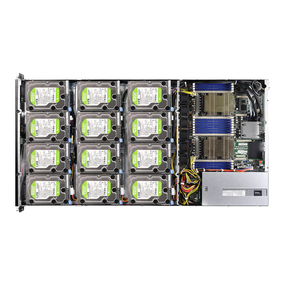
1U12XL-C622 RPSU 2.2 Internal Features... - Page 12 From Serverboard Power Supply Unit (PSU) 2 Power Supply Unit (PSU) 1 Power Distribution Board (PDB) VGA Port & COM Port System Fan 6 System Fan 5 System Fan 4 System Fan 3 System Fan 2 System Fan 1 HDD Backplane Board (BPB) 3.5"...
-
Page 13: System Front Panel
1U12XL-C622 RPSU 2.3 System Front Panel Description 2 x USB 2.0 Ports 2.5" SATA HDD Tray 0 (SSATA0) Control Panel Buttons and LEDs 2.5" SATA HDD Tray 1 (SSATA1) 2.4 System Rear Panel Description 2 x Power Supply Units I/O Shield (depends on the specification of the server board)* 1 x LAN Mezzanine Card Slot Rear Vent* COM Port... -
Page 14: Front Control Panel Buttons And Leds
2.5 Front Control Panel Buttons and LEDs Front Control Panel Description Power Button and LED System Reset Button LAN Status LED* HDD Status LED* System Fault LED UID Button and LED* *Please be noted that the functions are supported depending on the type of the server board. System Reset Button When the system is completely unresponsive, press the system reset button to reboot the server without shutting it off and initialize the system. - Page 15 1U12XL-C622 RPSU Status LED Definitions Power LED Status Description Green Power on Power off UID LED Status Description Blue System identification is active. System identification is disabled. LAN LED Status Description Green Link between system and network and no access Blinking Green Network access HDD Status LED...
-
Page 16: Chapter 3 Hardware Installation And Maintenance
Chapter 3 Hardware Installation and Maintenance This chapter helps you assemble the chassis and install components. Before You Begin Before you work with the server, pay close attention to the “Important Safety Instructions” at the beginning of this manual. 1. Make sure the server is powered off. Power down the server if it is still running. -
Page 17: Server Top Cover
1U12XL-C622 RPSU 3.1 Server Top Cover Removing the Server Top Covers 1. Before removing the top cover, power off the server and unplug the power cord. 2. The system must be operated with the chassis top cover installed to ensure proper cooling. 1. - Page 18 Installing the Server Top Covers 1. Lower the top covers on the chassis, making sure the side latches align with the cutouts. 2. Slide the top front cover toward the rear. 3. Secure the top covers with the screws.
-
Page 19: Hard Disk Drive
1U12XL-C622 RPSU 3.2 Hard Disk Drive 3.2.1 Installing a Hard Disk Drive into a 3.5" Hard Drive Carrier 1. Open the hard drive release lever. 2. Lower a 3.5" HDD into the carrier. 3. Carefully align the hard drive with the carrier and make sure it is well seated. 4. - Page 20 3.2.2 Installing a 2.5" Hard Disk Drive(or Solid-State Drive) into a 3.5" Hard Drive Carrier 1. Install the 2.5" HDD/SSD into bracket and align with the 2 screw holes on bracket. 2. Secure it to the bracket the screws. 3. Open the hard drive release lever. 4.
- Page 21 1U12XL-C622 RPSU 3.2.3 Installing a Hard Disk Drive into 2.5" Hard Drive Tray Removing 2.5” Hard Drive Trays from the Chassis 1. Press the locking lever latch on the drive tray to unlock the retention lever. 2. Rotate the lever out and away from the module bay and pull the hard drive out of the HDD tray.
- Page 22 Installing a 2.5” Hard Drive to the Hard Drive Tray 1. Place the 2.5" HDD into the tray with the printed circuit board side facing down. Carefully align the mounting holes in the hard drive and the tray. 2. Secure the hard drive using the four screws.
- Page 23 1U12XL-C622 RPSU 3. Slide the drive tray into the HDD bay until the drive is fully seated. 4. Push in the locking lever to lock the HDD tray into place.
-
Page 24: Power Supply
3.3 Power Supply The 1U12XL-C622 RPSU can accommodate two AC or two DC power supplies in the bay at the rear of the chassis. Each unit provides up to 700 Watts of power. Only a single power supply is required for operation, with the second power supply purely as a redundant, load- sharing backup. - Page 25 1U12XL-C622 RPSU Removing the Power Supply 1. Hold onto the power supply handle while pressing the locking lever towards the power supply handle. 2. Pull to remove the power supply from the chassis. 1. Before replacing the power supply, power off the server, unplug the power cord, and disconnect all wiring from the power supply.
-
Page 26: System Fan
3.4 System Fan Replacing the System Fan 1. Unplug the fan connecter and remove the failed fan. 2. Align the mounting holes on the fan bar with the fan mounts on the replacement fan corners. 3. Gently place the fan on the fan bar. Make sure the fan is well seated. 4. -
Page 27: Lan Mezzanine Card
1U12XL-C622 RPSU 3.5 LAN Mezzanine Card You can use an optional Ethernet mezzanine card for additional LAN ports. Please be aware that the mezzanine card must be used in conjunction with a matching I/O module. 1. Remove the screws that secure the blanking plate on the chassis. Keep the screws for later use. -
Page 28: Chassis Cables
3.6 Chassis Cables This section lists supported cables for your chassis system. Cable type and quantity vary depending on the server board that comes with your system. 1. PMBus Cable (500mm) (Quantity: 1) 2. VGA cable, DB9P/M TO 2*8P HSG Cable (150mm) (Quantity: 1) Server 3. - Page 29 1U12XL-C622 RPSU 5. Power Y-Cable for backplane (700mm) (Quantity: 1) 6. Power Cable, 8P CPU1 power (95mm) (Quantity: 1) 7. Power Cable, 8P CPU2 power (500mm) (Quantity: 1) 8. Power Cable, 24P main power (350mm) (Quantity: 1)
- Page 30 9. MiniSAS HD Cable (700mm) (Quantity: 1) 10. MiniSAS HD Cable (880mm) (Quantity: 1) 11. MiniSAS HD Cable (1040mm) (Quantity: 1) 12. SMBus Y Cable (650mm) (Quantity: 1)
- Page 31 1U12XL-C622 RPSU 13. USB Cable, USB 2.0 Cable (830mm) (Quantity: 1) Server 14. COM Dongle Cable (100mm) (Quantity: 1) Server...
Need help?
Do you have a question about the 1U12XL C622 RPSU and is the answer not in the manual?
Questions and answers