Table of Contents
Advertisement
Quick Links
Advertisement
Table of Contents
Troubleshooting

Related Manuals for GE Responder 2000


Summary of Contents for GE Responder 2000
- Page 2 Revision History The revision letter identifies the document’s update level and changes with every update of the manual. Part Number and Revision Date Comment 2025653-048A 10/2006 Initial Release 2025653-048B 10/2007 Updated LCD cable routing picture; Updated from version 2.12 software to version 2.22;...
-
Page 3: Table Of Contents
TABLE OF CONTENTS ........................EVISION ISTORY SECTION 1: INTRODUCTION ......................8 ............................. 8 VERVIEW ..........................9 ESCRIPTION ......................10 ONTROLS AND NDICATORS ....................11 ENERAL ERVICE NFORMATION Navigation..........................11 Passwords ..........................11 Battery Maintenance......................11 SECTION 2: MAINTENANCE ....................... 12 ........................... - Page 4 No ECG from Paddles/Pads/Spoons ..................25 Service Required LED is ON....................25 SECTION 4: REPAIR ........................26 ........................... 26 VERVIEW ........................27 EQUIRED OOLS ......................27 ISASSEMBLY VERVIEW ................... 28 OW TO EPLACE PECIFIC OMPONENTS Capacitors (see page 47) ...................... 28 Therapy Board (see page 46) ....................
- Page 5 Send Event Logs to PC........................58 Send/Receive Stored Parameters ....................59 ........................60 ISUAL NSPECTION ........................60 PERATIONAL ESTS Initial Power Up ........................60 Maintenance Mode Tests ...................... 61 Verify Serial Communications ....................61 Required Equipment ........................61 Procedure ............................61 Defibrillator Tests........................
- Page 6 Power Connector – IEC 320 type – AC Power................114 Paddles/Pads Connector – GE Defibrillator Paddles ..............114 Paddle Connector ID Codes ......................115 ECG Connector – GE ECG Connector – Five lead ECG .............. 115 ™ 2025653-048 Revision B...
- Page 7 ECG Cable Identification Encoding....................116 Connector – GE SpO ......................117 Serial Service Connector – DB9-Female ..................117 Paddle Cradles (Test Load) ......................117 MAIN CPU PCBA ........................ 118 J211 - Power Control Interface to Power Control PCBA ............... 118 J214 –...
-
Page 8: Section 1: Introduction
This chapter contains general information for servicing the Responder 2000. This Service manual assumes familiarity with the controls and basic operation of the Responder 2000. Detailed information regarding controls, operation, set-up, and regular maintenance procedures are found in the Operator’s manual. -
Page 9: Description
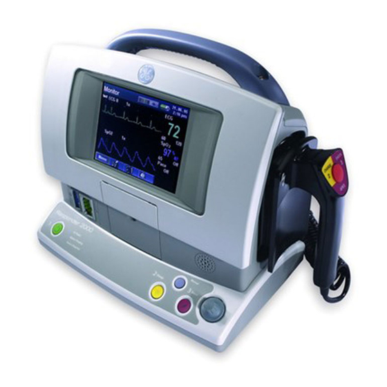
SECTION 1: Introduction Description The Responder 2000 is a defibrillator/monitor/pacemaker intended for use by personnel trained in its operation. The device is lightweight, portable, easy to use and reliable. It incorporates a 320 x 240 transmissive color TFT color display for wide viewing angles in all light conditions. -
Page 10: Controls And Indicators
SECTION 1: Introduction Controls and Indicators ™ 2025653-048 Revision B Responder 2000 Page 10... -
Page 11: General Service Information
Refer to the Operator’s Manual for setup (and configuration options) required before placing the Responder 2000 into service. Navigation Use the Rotary Selection knob to navigate the Responder 2000 user interface. The Rotary Selection knob is used for: Scrolling through menus and sub-menus •... -
Page 12: Section 2: Maintenance
SECTION 2: Maintenance SECTION 2: Maintenance Overview Use the following procedures to upgrade the Responder 2000 software: Upgrade Software to update one or more software files • Upgrade Printer Software to upgrade printer software and fonts • TOPIC PAGE Equipment Setup... -
Page 13: Equipment Setup
Note: When performing a software upgrade, the Responder 2000 must be running on AC power. Connect serial cable between the communications port of the PC and the serial port of the Responder 2000. At the desktop on the PC, double-click the Responder 2000 Upgrade icon to open the CodeLink 2000 program. -
Page 14: Upgrade Software
Browse to the folder (or file) to be uploaded and click OK (or Open). While the files are updating, the status of each file is displayed. As the files are updated, the Shock button and then the Manual button flash on the Responder 2000. When all files are updated, a confirmation screen is displayed Verify Pass is displayed for each file and click OK. - Page 15 A text file with the software version numbers is included with the upgrade folder. Compare those software version numbers to the versions listed on the Responder 2000. Press and hold the Power button for 5 seconds to reboot the Responder 2000. Highlight and click the System Menu.
-
Page 16: Upgrade Printer Software
Click Open. While the file is updating, the status of the file is displayed. As the file is updated, the Shock button and then the Manual button flash on the Responder 2000. When the file is updated, a confirmation screen is displayed: Verify Pass is displayed for the file and click OK. -
Page 17: Update Serial And Model Numbers
When replacing the Main Board, the Serial and Model numbers must be updated. Before replacing the Main Board, record the Serial and Model numbers from the About screen. Note: If the Responder 2000 cannot be booted, record the model and serial number from the back panel label. Replace the Main Board. -
Page 18: Section 3: Troubleshooting
SECTION 3: Troubleshooting SECTION 3: Troubleshooting Overview This section describes how to troubleshoot the Responder 2000. These instructions are intended for use only by service providers who are specifically trained to service the Responder 2000. TOPIC PAGE Safety Precautions Who Should Perform Repairs... -
Page 19: Safety Precautions
Before servicing the Responder 2000, disconnect the AC power cord and remove the battery. WARNING: Shock Hazard or Equipment Damage Internal components of the Responder 2000 may still contain high voltages even after the AC power cord and battery are removed. Before working on any internal component, verify high voltages are not present. -
Page 20: Repair Tools And Equipment
SECTION 3: Troubleshooting Repair Tools and Equipment The following tools are needed to perform the procedures in this section. TR15 Safety Torx • TR25 Safety Torx • Serial cable for software upgrades (with Windows 2000 or XP PC) • Software upgrade kit •... -
Page 21: No Boot
Boot, but no Response Use this procedure to troubleshoot the Responder 2000 when the unit seems to boot up normally (i.e., the Front Panel LEDs flash and a speaker tone is heard when the Power button is pressed), but does not respond to any subsequent user input. -
Page 22: Bad Front Panel Leds
SECTION 3: Troubleshooting Bad Front Panel LEDs Use this procedure to troubleshoot the Responder 2000 when the Front Panel LEDs are not displaying correctly. Normal operation is indicated by: At system boot, all LEDs will flash. Green AC Power LED is lit when the unit is plugged in. -
Page 23: Bad Speaker
SECTION 3: Troubleshooting Bad Speaker Use this procedure to troubleshoot the Responder 2000 when the Speaker is not working correctly. Note: The Speaker cannot be removed from the Front Panel. If the speaker must be replaced, the entire Front Panel must be replaced. -
Page 24: Battery Troubleshooting
Replace the Battery. Replace Power Control Board. Replace Main Board. Not Working Verify the Responder 2000 has a SpO Main Board installed. Check the About screen. “SpO2 - - - -” indicates a non-SpO Main Board is installed in the unit. -
Page 25: Shock Into Patient Fails
SECTION 3: Troubleshooting Shock into Patient Fails Perform a button test for each Paddle. If the test fails, replace the Paddle. If the test does not fail, connect the Paddles/Pads/Spoons to a simulator and attempt to shock. If the shock is successful: The unit is working correctly. -
Page 26: Section 4: Repair
SECTION 4: Repair Overview This section describes how to assemble and disassemble the Responder 2000. These instructions are intended for use only by service providers who are specifically trained to service the Responder 2000. This section is divided into two parts: How to Replace Specific Components: Provides high-level disassembly steps with references to the assembly steps. -
Page 27: Required Tools
SECTION 4: Repair Required Tools The following tools are necessary to Assembly/ Disassembly the Responder 2000. Note: The Security Torx is also known as Tamper Resistant Torx. T15 Security Torx driver T25 Security Torx driver Philips Screwdriver Tube of Silicone Disassembly Overview WARNING: Lethal Shock Hazard. -
Page 28: How To Replace Specific Components
How to Replace Specific Components Use the following procedures as a guide to replace specific internal components in the Responder 2000. Not all components are listed. (For example, if the Front Body is damaged and must be replaced, the entire unit must be disassembled and then reassembled using the more detailed Assembly instructions). -
Page 29: Spo2 Board
SECTION 4: Repair SPO2 Board (see page 44) Note: Most SP02 failures are the result of bad sensors. Before replacing the SPO2 Board, be sure to complete the troubleshooting procedure on page 24 to verify the board is the cause of the fault. Follow the Capacitor and Therapy Board instructions (above) to remove the Capacitors and Therapy Board. -
Page 30: Display/Main Board/Printer
SECTION 4: Repair Display/Main Board/Printer (see page 42) Follow the Capacitor, Therapy Board, SPO2 Board, and ECG Board instructions (above) to remove the Capacitors Therapy Board, SPO2 Board, and ECG Board. Remove the screws holding the Front Bezel (see Figure 45: Front Bezel Installed). Remove the screws holding the Display (see Figure 43: LCD Screw Locations). -
Page 31: Assembly
SECTION 4: Repair Assembly Overview The following section details the assembly steps starting from a fully disassembled Responder 2000. When replacing a single board or other component, not all reassembly steps may be applicable. WARNING: Lethal Shock Hazard. In the event of equipment failure, the two main capacitors may retain dangerous voltages even if the Responder 2000 is disconnected from AC power and the battery is removed. -
Page 32: Main Board And Printer Installation
SECTION 4: Repair Main Board and Printer Installation Assembly Step Details Install Ribbon Cables on Main Board at J210 and J218. Note: Ensure the colored strip on cable into J218 is visible when board is oriented as shown. Note: Ensure cables are installed correctly as shown below. - Page 33 SECTION 4: Repair Assembly Step Details Place the Main Board and Printer into the Front Body. Tuck the ribbon cables connected to J210 and J218 as shown. Secure the Main Board with seven Philips screws Figure 12: Cable and install the copper Detail Figure 11: Main Board Contact Spring as shown.
- Page 34 SECTION 4: Repair Assembly Step Details Connect the EGG cable (and optional SPO2 cable) to the cable cover. Secure to the Front Body assembly with four Phillips screws Note: Ensure the heart symbol is not upside-down. Figure 17: Correct Orientation Figure 16: ECG Cable Cover Installed Insert the Rotary Selection...
- Page 35 SECTION 4: Repair Assembly Step Details Connect the CPU Main Cable to Main Board J211. Figure 20: CPU Main Cable ™ 2025653-048 Revision B Responder 2000 Page 35...
-
Page 36: Power Control Board And Power Supply Installation
SECTION 4: Repair Power Control Board and Power Supply Installation Assembly Step Details Pass the three cables through the holes in the Lower Frame as shown. Secure the Lower Frame to the Front Body with six Torx security screws. Figure 21: Lower Frame (Bottom View) Route the ECG Cable as shown and pass it back up into the main compartment. - Page 37 SECTION 4: Repair Assembly Step Details Snap the two black Brackets into place on the Lower Frame. Note: Check the Power Supply green ground wire to ensure it is properly soldered on both ends and is in good condition. Place the Power Supply on the Brackets.
- Page 38 SECTION 4: Repair Assembly Step Details Secure the Power Control Board with five Phillips screws. Place the Service Connector (serial connector) on the Lower Frame. Figure 31: Note: Pin 1 must be at the Service Connector (Correct top. Orientation) Route and connect all cables as shown.
- Page 39 SECTION 4: Repair Assembly Step Details Install the Battery Latch in the Base Cover. Apply Silicone to the notch for the AC power plug. Figure 35: Battery Latch Figure 36: Silicone Applied Install the Base Cover to the Lower Frame. Using five Torx security screws (white arrows).
-
Page 40: Ecg Board Installation
SECTION 4: Repair ECG Board Installation Assembly Step Details Install the ECG Insulator in the Front Body. Figure 39: ECG Insulator Installed Install the ECG Board to the Front Body by connecting J412 on the ECG Board to J212 on the Main Board. - Page 41 SECTION 4: Repair Assembly Step Details Note: The next section details the Front Bezel and Display replacement. That procedure includes steps to route the ECG cable and install the ECG Shield for the ECG Board. Even if the Display or Front Bezel is not replaced, those steps must still be completed (see Figure 47 and Figure 48).
-
Page 42: Display Installation
Figure 44: LCD Backlight Cable (Properly Routed) Caution: Shock Hazard or Equipment Damage. The Responder 2000 is energized for the following step to verify proper operation. Exposed circuit boards may contain potentially dangerous voltages. Do not touch exposed electronics and keep all tools clear while performing the verification. - Page 43 SECTION 4: Repair Assembly Step Details If necessary, remove protective paper and plastic from inside the Front Bezel. Caution: Equipment Damage. Do not touch the inside of the Front Bezel. Clean the LCD and inside of the Front Bezel with a brush or compressed air.
-
Page 44: Spo 2 Board Installation
SECTION 4: Repair Board Installation Assembly Step Details Perform the Following step only if the SPO2 option is installed. Connect the ECG/SPO2 cable to X16 on the SPO2 Board. Connect X14 on the SPO2 Board to J221 on the Main Figure 49: SPO Cable Figure 50: SPO... -
Page 45: Therapy Board Installation
SECTION 4: Repair Therapy Board Installation Assembly Step Details Connect the ribbon cable to J110 on the Therapy Board. Note: See the Ribbon Cable Installation Notes for proper installation (Figures 6, 7 and 8). Fold the connected cable under the Therapy Board. Figure 53: Ribbon Cable Figure 52:... -
Page 46: Capacitor Installation
SECTION 4: Repair Capacitor Installation Assembly Step Details Insert one tie wrap through each capacitor support bracket. The tie wraps are used to secure the Therapy Board power cable, left Charge Drain cable, and the Capacitor lead wires after the lead wires are connected. -
Page 47: Rear Cover Installation
SECTION 4: Repair Rear Cover Installation Assembly Step Details If necessary, insert Rubber Tubing (279 mm ±3 mm 11 in ± 1/8 in) into the groove on the Front Body. Note: See Figure 33 for installation note. Figure 61: Front Body Tubing Installed Install Handle to the Rear Body with two Torx security screws and two washers. - Page 48 SECTION 4: Repair Assembly Step Details Connect P101 (Red Paddle wire) from Rear Body to J101 on the Therapy Board. Then connect P102 to J102. Connect gray Paddle Cable to J109 of Therapy Board. Notes: Ensure the wires are routed exactly as shown.
- Page 49 SECTION 4: Repair Assembly Step Details Install Rear Body to Front Body using five small Torx security screws and two large Torx security screws. Note: Tighten all screws slowly and evenly. Check for bulges, gaps, or pinched wires before tightening completely.
-
Page 50: Section 5: Performance Verification And Safety Testing
Section 5: Performance Verification and Safety Testing Section 5: Performance Verification and Safety Testing Overview This section describes how to perform service maintenance and testing of the Responder 2000 after repairs are performed. TOPIC PAGE Required Equipment Preventive Maintenance Annual Inspection... -
Page 51: Required Equipment
PRECAUTION: Do not shock into devices with highly non-linear resistance versus the voltage, (e.g. an overvoltage protector). This may damage the Responder 2000. Do not use the HELLIGE Test Lamp 301 495 00 for testing. This test lamp includes an overvoltage protector. Shocking into it may damage the Responder 2000. -
Page 52: Verify Operation
After service, the following operational and safety procedures must be performed to verify proper operation. All tests indicated must be performed before the Responder 2000 can be returned to the customer. Depending on the type of repair, the following procedures must be performed for each of the following cases: External Repairs or Replacement •... -
Page 53: Maintenance Menu Reference
Maintenance Menu Reference Caution: Loss of Patient Data Do not enter Maintenance mode while the Responder 2000 is connected to a patient. Patient data may be lost. Perform any Maintenance mode procedures outside the patient vicinity. Note: The Responder 2000 battery must have at least a 20% charge before performing these procedures. -
Page 54: Service Tests
Section 5: Performance Verification and Safety Testing The Maintenance Menu has the following items: Service Tests: These tests, described below, are used to verify operation • Device Configuration: Used to set the language • Stored Data Management: Used to clear stored data or settings, transfer stored logs to a PC, and save or load •... -
Page 55: Printer Speed Test
Normally this screen is used to verify the battery is charging (or fully charged) at the appropriate voltage. Service tests must be performed with the battery at least 20% charged. New batteries have a full capacity of at least 6000 mAH and will charge when the Responder 2000 is plugged •... -
Page 56: Display Test
Display Test The following colors fill the entire display in succession: White, Red, Green, Blue, and Black. Verify no pixels are stuck or missing. After the test, the Responder 2000 then automatically cycles power. ECG Lead Test Displays lead status (on or off). See the ECG Lead Test Procedure on page 67 for proper indications. -
Page 57: Temperature Readings
Section 5: Performance Verification and Safety Testing Temperature Readings Displays internal temperatures for the Power Board, Therapy Board, Printer, and Battery. These readings may vary according to fan speed or external conditions. An abnormally high reading may indicate a fan not working or other fault. The internal fan should turn on at the following temperatures: Fan ON (High) Fan ON (Low) -
Page 58: Device Configuration
Select Language Sets the system language to: English, French, German, Italian, Dutch, Portuguese, Russian, Spanish, or Swedish. Once a new language is selected, the Responder 2000 cycles power. Note: Maintenance mode text is always in English, regardless of the language selected. -
Page 59: Send/Receive Stored Parameters
Select the parameters to be uploaded and click Open. A progress bar is displayed Check the Responder 2000 display. If Params Set is displayed, the upload was successful. Click No to upload the parameters file again. If the parameters file was not uploaded successfully, retry as necessary. -
Page 60: Visual Inspection
The Responder 2000 is ready for use in about 4 seconds. • The AC Power LED and Battery Charging LED are lit when a battery is installed and the Responder 2000 is connected to AC power The AC Power LED is not lit and Battery Charging LED is not lit when a battery is installed and the Responder •... -
Page 61: Maintenance Mode Tests
Turn off the Responder 2000. Shut down the PC. Connect the Serial cable from the Serial port on the Responder 2000 to the Serial port on the PC. Turn on the PC. Open Responder 2000 Upgrade program on the PC. -
Page 62: Defibrillator Tests
Before delivering any shock, ensure all personnel and equipment are clear of the test area. Energy Timeout Test Ensure the Responder 2000 has a charged battery (at least 25%) installed and is connected to AC power Seat each paddle in its side holder. Ensure paddles are securely seated. -
Page 63: Paddles Test
Press the Manual button on the Responder 2000. Select Energy Level of 270J. Press Charge button on front panel. Verify the Responder 2000 charges to a 270J level and the audible alarm sounds. Press the Shock buttons on the front panel. -
Page 64: Pacing Test
Section 5: Performance Verification and Safety Testing Pacing Test Connect pads cable to the back of therapy connector on the back of Responder 2000. Connect pads to a Calibrated Impulse 4000 Defib/Pacer Analyzer or equivalent. Turn on the Responder 2000. -
Page 65: Ecg Tests
Plug in the ECG Cable the ECG Cable Port on the Responder 2000. Change ECG source to ECGII. Select ECG > Norm > 80 on the ECG Simulator and verify the following on the Responder 2000: The ECG signal on screen of Responder is correct amplitude and polarity •... -
Page 66: Lead Detection Test
14. Verify the following leads may be selected: Paddles ECG I ECG II ECG III 15. Disconnect 3 Lead ECG cable from Responder 200 and connect 5 Lead ECG cable to Responder 2000. 16. Verify the following leads may be selected: Paddles ECG I ECG II ECG III ™... -
Page 67: Ecg Lead Test
Section 5: Performance Verification and Safety Testing ECG Lead Test Connect the ECG leads to the patient simulator. On the Responder 2000, select ECG Lead Test from the Maintenance menu. Verify ECG Lead Status display as shown: Disconnect RA (White Lead) from Patient Simulator and verify the display as shown: Reconnect RA lead to patient simulator. -
Page 68: Paddles Ecg Test
QRS complex of the beat and the Cardioversion function is automatically reset. If the delay time is greater than 60ms, the test has failed. Operation Perform this test only if the Responder 2000 is equipped with the SpO option. Plug in the SpO sensor connector. -
Page 69: Safety Tests
WARNING: Shock Hazard. Do not touch the Hipot tester, the Responder 2000, or any leads during the test. Ensure all Hipot leads are electrically isolated before starting the test. If the test is performed on an anti-static mat, ensure the leads do not contact the mat during the test. -
Page 70: Ecg To Serial 4.0 Kvac Test
Section 5: Performance Verification and Safety Testing ECG to Serial 4.0 KVAC Test Setup the Hipot tester: 4.0 KVAC • High current limit 4.0 mA • Test 30 Sec.: Ramp 2.0 Sec. • 120 VAC (±10 %) Input • Plug in the ECG Connector Test Fixture into the ECG port. Plug the Serial Port Test Fixture into the Serial port. -
Page 71: Apex Test Load To Apex And Sternum 3.0 Kvdc Test
Section 5: Performance Verification and Safety Testing Apex Test Load to Apex and Sternum 3.0 KVDC Test Note: The previous test settings were testing DC voltage. This test procedure requires setup for AC voltage. Setup the Hipot tester: 3.0 KVAC •... -
Page 72: Leakage Current Test
Section 5: Performance Verification and Safety Testing Leakage Current Test Required Equipment Metron QA-90 Safety Analyzer (or equivalent) • Equipment Setup Note: This setup assumes the use of a Metron QA-90 Safety Analyzer. If an equivalent safety analyzer is used, refer to the Operator’s manual for detailed instructions. - Page 73 Section 5: Performance Verification and Safety Testing Leads Name Limit Patient Leakage Current AC (OS) 500 A Patient Leakage Current AC (NC) 100 A Patient Leakage Current AC (OE) 500 A Patient Leakage Current AC OSRM 500 A Patient Leakage Current AC NCRM 100 A Patient Leakage Current AC OERM 500 A...
- Page 74 Plug the 5 ECG cable leads from ECG Cable Port into Patient Lead connectors 3-7. Plug cable from Dfib Paddle Port into Patient Lead connectors 1 and 2. (For SpO equipped Responder 2000 only) Plug cable from Sp02 connector to Patient Lead connector 8. ™ 2025653-048 Revision B...
-
Page 75: Test Procedure
Press Responder 2000 Power button to turn on. Turn on the Safety Analyzer and wait for the self test to complete. If previously saved, select the stored Responder 2000 parameters. Press START on the Safety Analyzer to begin the tests. -
Page 76: Leakage Current "Measurement Device" (Md) Characteristics
The defibrillator electrodes as well as handles and holder recesses must be free of any cream residue. The defibrillator electrodes, pacemaker cable, ECG cable, SPO cable and Responder 2000 power cord should be checked for any visible external damage to the insulation and strain relief. -
Page 77: Leakage Current
Section 5: Performance Verification and Safety Testing Leakage Current The leakage currents correspond to 110 % of rated voltage for the tested unit. Most Safety Testers take this into account; otherwise the measured values have to be calculated. Use of a “Safety Tester” as show or equivalent test setup (i.e. equivalent test configurations need not •... - Page 78 Section 5: Performance Verification and Safety Testing Earth leakage (AC Line) Perform the following tests, with the applicable switch settings on the “Safety Tester” and record the results in the applicable test form(s). UUT power switch in the “ON” position. •...
- Page 79 Section 5: Performance Verification and Safety Testing Enclosure (Chassis) leakage Perform the following tests, with the applicable switch settings on the “Safety Tester” and record the results in the applicable test form(s). UUT power switch in the “ON” position. • TP1 connected to accessible metal parts (see tables below for individual test points).
-
Page 80: Patient Leakage Current To Ground
Section 5: Performance Verification and Safety Testing Patient Leakage Current to Ground Perform the following tests, with the applicable switch settings on the “Safety Tester” and record the results in the applicable test form(s). UUT power switch in the “ON” position. •... - Page 81 Section 5: Performance Verification and Safety Testing S1: DPDT S2: SPDT S3: SPDT S4: SPDT Test Description Maximum Polarity Neutral Ground Test point Limits a) Normal a) Closed a) Closed a) Internal b) Reverse b) Open b) Open b) TP1 (uA) Position Position...
- Page 82 Section 5: Performance Verification and Safety Testing S1: DPDT S2: SPDT S3: SPDT S4: SPDT Test Description Maximum Polarity Neutral Ground Test point Limits a) Normal a) Closed a) Closed a) Internal b) Reverse b) Open b) Open b) TP1 (uA) Position Position...
-
Page 83: Patient Leakage Current, Mains On Applied Part (All Sip/Sops Grounded)
Section 5: Performance Verification and Safety Testing Patient Leakage Current, Mains on Applied Part (All SIP/SOPs Grounded) Perform the following tests, with the applicable switch settings on the “Safety Tester” and record the results in the applicable test form(s). Disconnect the “Safety Tester” from the “Mains Supply” Ensure the battery is removed Configure the test set up as shown (or equivalent) UUT hot/neutral/ground connected to ground... - Page 84 Section 5: Performance Verification and Safety Testing Test Description S1: DPDT S2: SPDT S3: SPDT S4: SPDT Polarity Neutral Ground Test point Maximum Limits a) Normal a) Closed a) Closed a) Internal b) Reverse b) Open b) Open b) TP1 (uA) Position Position...
-
Page 85: Insulation Resistance
Section 5: Performance Verification and Safety Testing Insulation Resistance Perform the following tests, with the applicable resistance range settings and record the results in the applicable test form(s). Disconnect from the SUPPLY MAINS Remove battery Remove I/O (RS-232) cable UUT power switch in the “ON” position. The resistance values shall not be less than: 2 M between MAINS PART and all other parts separated by basic insulation, including TYPE B APPLIED •... -
Page 86: Section 6: Parts And Accessories
SECTION 6: Parts and Accessories To order service parts for the responder 2000, contact: GE Healthcare Technologies Service Logistic Center 79111 Freiburg Munzinger Straße 3-5 Germany Overview This section lists parts and accessories for the Responder 2000. TOPIC PAGE Kits Accessories Power Cords ™... -
Page 87: Kits
SECTION 6: Parts and Accessories Kits Kit Part Number Kit Description Part Photograph 2029882-001 Therapy Board Kit Therapy Board with Cables Therapy Board Left Drain Cable 2029882-002 Right Drain Cable Therapy Board Cables Only Therapy Board to Power Control Board Cable Therapy Board to Main Board Ribbon Cable 2029882-003... - Page 88 SECTION 6: Parts and Accessories Kit Part Number Kit Description Part Photograph 2029882-008 Power Control Board Kit Power Control Board and Power Control Board Cables Service Connector (with Cable) 2029882-009 Power Control Board Main Wire Set for Power Control Board Cable Board Power Control Board to Therapy Board Cable...
- Page 89 SECTION 6: Parts and Accessories Kit Part Number Kit Description Part Photograph 2029882-012 Main Capacitors Kit High Voltage Capacitor Set Main Capacitors (2) 2029882-013 Rear Cover Kit Rear Cover with Defib Rear Cover (Including Connector Paddle Cables and Paddle Wires) 2029882-016 Handle Device Handle Only...
- Page 90 SECTION 6: Parts and Accessories Kit Part Number Kit Description Part Photograph 2029882-018 Display Kit LCD Set with Retainer Display Retainer Copper Contact Spring 2029882-019 Display Assembly (including LCD Retainer only Backlight cable) Display to Main Board ribbon cable 2029882-020 Printer Kit Printer Assembly Printer Assembly...
- Page 91 SECTION 6: Parts and Accessories Kit Part Number Kit Description Part Photograph 2029882-023 Front Bezel Kit Front Bezel Kit Front Bezel 2029882-024 Front Body Kit Front Body Kit Paddle Latches (with Springs) (2) Paddle Latches (2) Front Body Speaker (not shown) Note: Speaker is integral to Front Body and not available separately.
-
Page 92: Accessories
SECTION 6: Parts and Accessories Accessories Accessory Part Number Part Description Part Photograph OXY-RWL Datex-Ohmeda Replacement Datex-Ohmeda Foam Wrap Large Foam Wrap OXY-RTW Datex-Ohmeda Replacement Wide Datex-Ohmeda Wide Adhesive Adhesive Tape Tape 2030137-001 Paddles with two adult surface Paddle Pair, Responder plates 2030134-001 Responder Paddle Electrode... - Page 93 SECTION 6: Parts and Accessories Accessory Part Number Part Description Part Photograph 60-mm Thermal Paper (Box of 50) 2026327-001 Thermal Paper Rechargeable Battery 2025267-001 Rechargeable Battery ™ 2025653-048 Revision B Responder 2000 Page 93...
-
Page 94: Power Cords
SECTION 6: Parts and Accessories Power Cords Europe Argentina Denmark 2020387-002 2020387-003 2020387-004 India and South Africa Italy Japan 2020387-005 2020387-006 2020387-007 Israel Australia 2020387-009 2020387-010 2020387-011 ™ 2025653-048 Revision B Responder 2000 Page 94... -
Page 95: Section 7: Theory Of Operation
SECTION 8: Specifications and Safety SECTION 7: Theory of Operation Overview This section provides descriptions of the Responder 2000 and its components. These instructions are intended for use only by service providers who are specifically trained to service the Responder 2000. TOPIC... -
Page 96: System Overview
SECTION 8: Specifications and Safety System Overview The Responder 2000 system has the following functions and features. Note: Refer to the Operator’s Manual for specific instructions and intended use. Functions Defibrillation (with dedicated Defibrillator operation buttons) 2J to 270J Biphasic waveform (can deliver 270J Biphasic shock into a 50 Ohm load) •... -
Page 97: System Interconnection Block Diagram
SECTION 8: Specifications and Safety System Interconnection Block Diagram ™ 2025653-048 Revision B Responder 2000 Page 97... -
Page 98: Component Descriptions
SECTION 8: Specifications and Safety Component Descriptions Main Board The Main Board controls all major subsystems and user interface. Controls defibrillation (J210), pacing, ECG (J212), and SpO (J221) functions Controls the display interface and provides 3.3V (J214) and high voltage backlight power (J213) for LCD. Controls (J219) and provides 5V (J220) for the Printer Controls the speaker (J216) Software upgrade path through the serial port (pass-through from the Power Control Board) -
Page 99: Section 8: Specifications And Safety
SECTION 8: Specifications and Safety SECTION 8: Specifications and Safety Overview This section presents the specifications and safety standards of the Responder 2000. TOPIC PAGE Specifications Physical Dimensions Environmental Requirements ® RHYTHMx ECG Analysis Algorithm ® STAR BIPHASIC Defibrillation Waveform... -
Page 100: Specifications
SECTION 8: Specifications and Safety Specifications Display Size: 115.2mm X 86.4mm Type: Transmissive Color TFT LCD Resolution: 320 X 240 pixels Number of waveform channels: Defibrillator Waveform: Biphasic truncated exponential Charge Time: 7 seconds nominal Delivery Method: Via pads, paddles or spoons Paddles and Pads Energy Selections (50 2, 3, 5, 7, 10, 15, 20, 30, 50, 70, 100, 150, 200, 270 load):... - Page 101 Battery Capacity: 50 shocks, or 240 minutes monitoring time, or 72 minutes monitoring time with pacing Battery Charge Time: 8 hours in Responder 2000, 4 hours in external charger, 20 hours for calibration cycle in external charger Battery Standby: 6 months Battery Life: 2.5 years or 300 Battery charge-discharge cycles,...
-
Page 102: Physical Dimensions
CAUTION: Cold Environments If the Responder 2000 is stored in an environment with a temperature below the operating temperature, the unit should be allowed to warm up to the needed operating temperature before using. ™... -
Page 103: Rhythmx ® Ecg Analysis Algorithm
• Continuous Monitoring The Responder 2000 rejects all T-waves that are 1 millivolt or less in the conditions specified in ANSI/AAMI EC 13 section 4.1.2.1c. The Responder 2000 will alarm tachycardia in the conditions specified in ANSI/AAMI EC 13 section 4.1.2.1 g) in less than 10 seconds. -
Page 104: Sync Mode
The pacer pulse detector will not respond to the waveform of ANSI/AAMI figure 5d, since this waveform is below the threshold of the Responder 2000 pacer pulse detector. The minimum typical slew rate in V/s RTI that will trip the pacer detector is 6.2 V/s for the 3 and 5 lead ECG. -
Page 105: Star ® Biphasic Defibrillation Waveform
SECTION 8: Specifications and Safety ® STAR BIPHASIC Defibrillation Waveform The waveform generated by the Responder 2000 is a BIPHASIC TRUNCATED EXPONENTIAL waveform compliant with ANSI/AAMI DF80. ® STAR Biphasic Waveform – 270J into Pads or paddles Table A - 270J Waveform into Different Resistive Loads (Typical Values) Patient’s... -
Page 106: Energy Levels And Patient Impedance
SECTION 8: Specifications and Safety Energy Levels and Patient Impedance The Biphasic Truncated Exponential (BTE) waveform delivers energy that is variant with the patient impedance. The waveform is designed to deliver the selected energy when the patient impedance is 50 Ohms, as shown in the above waveform table. -
Page 107: Electromagnetic Compatibility Requirements
Defibrillators (including automated external defibrillators) Electromagnetic Compatibility Requirements The Responder 2000 meets the requirements of the following EMC standards, as required by IEC 60601-2-4.: IEC 60601-1-2 (2001), Medical electrical equipment Part 1: General requirements for safety 2. Collateral standard: electromagnetic compatibility - Requirements and tests. -
Page 108: Environmental Standards
Environmental Standards Shock and Vibration The Responder 2000 is tested per the following when in the unpackaged condition: Bump: IEC 60068-2-29 (1987), Test EB: bump; 25g, 6 ms, 0.9 m/s ∆V, and 1000 bumps in each direction Sine Vibration: IEC 60068-2-6 (1995), Environmental testing - part 2. tests - test FC: Vibration (sinusoidal); 0.15mm... -
Page 109: Electromagnetic Emissions Table
Electromagnetic Emissions Table Guidance and manufacturer’s declaration – electromagnetic emissions The Responder 2000 is intended for use in the electromagnetic environment specified below. The customer or the user of the Responder 2000 should assure that it is used in such an environment. -
Page 110: Electromagnetic Immunity Table
Electromagnetic Immunity Table Guidance and manufacturer’s declaration – electromagnetic immunity The Responder 2000 is intended for use in the electromagnetic environment specified below. The customer or the user of the Responder 2000 should assure that it is used in such an environment. - Page 111 SECTION 8: Specifications and Safety Guidance and manufacturer’s declaration – electromagnetic immunity The Responder 2000 is intended for use in the electromagnetic environment specified below. The customer or the user of the Responder 2000 should assure that it is used in such an environment.
- Page 112 To assess the electromagnetic environment due to fixed RF transmitters, an electromagnetic site survey should be considered. If the measured field strength in the location in which the RESPONDER 2000 is used exceeds the applicable RF compliance level above, the RESPONDER 2000 should be observed to verify normal operation.
-
Page 113: Rf Communications Table
Recommended separation distances between portable and mobile RF communications equipment and the Responder 2000 The RESPONDER 2000 is intended for use in an electromagnetic environment in which radiated RF disturbances are controlled. The customer or the user of the RESPONDER 2000 can help prevent electromagnetic interference by maintaining a minimum distance between portable and mobile RF communications equipment (transmitters) and the RESPONDER 2000 as recommended below, according to the maximum output power of the communications equipment. -
Page 114: Connectors
Connectors The following sections describe connectors in the subassemblies within Responder 2000 Defibrillator. Case The case serves both as a housing and mechanical structure for the Responder 2000. Power Connector – IEC 320 type – AC Power Connector: Heyco 0916... -
Page 115: Paddle Connector Id Codes
Short to PC15 21730801 Internal Spoons 4.7K to PC15 Short to PC15 30344625 Responder Paddles Short to PC15 ECG Connector – GE ECG Connector – Five lead ECG Connector: GE 401760-1 Description Number Name Input – Right Arm No Connection No Connection Input –... -
Page 116: Ecg Cable Identification Encoding
Shield ECG Cable Identification Encoding ECG Cables available for use with the Cardiac Science Responder 2000 have identification features to enable identification of the cable type. Cable connections are shown here: Cable Connections for 5 lead, 3 lead and sync cables. -
Page 117: Spo Connector - Ge Spo
SECTION 8: Specifications and Safety Connector – GE SpO Connector: GE 401762 Name Description Number SPO2_RCAL Input – Calibration Data SPO2_LED- Output – Led Neg SPO2_LED+ Output – Led Pos SPO2_ANODE Input – Detector Pos GNDF Isolated Floating Ground SPO2_RCAL_GND Ground –... -
Page 118: Main Cpu Pcba
SECTION 8: Specifications and Safety MAIN CPU PCBA The main CPU PCBA is the nucleus of the system, with all major subsystems connecting to this board. J211 - Power Control Interface to Power Control PCBA AMP 1-103638-3 Name Description Number Not Used Fan_/Drive Pull Down Active Fan Drive... -
Page 119: J214 - Lcd Panel
SECTION 8: Specifications and Safety J214 – LCD Panel Hirose FH12-40-S-0.5SH Name Description Number 1-4, 6, No Connection 31,36 5, 10, 14, System Ground 18, 22, 26, 30, 32, 34 LCD_R0 Output - Red Bit 0 LCD_R1 Output - Red Bit 1 LCD_R2 Output - Red Bit 2 LCD_R3... -
Page 120: J213 - Lcd Ccfl Backlight
SECTION 8: Specifications and Safety Hirose FH12-40-S-0.5SH Name Description Number LCD_DRDY Output - LCD Frame Shift 37-40 +3.3V Power Output - LDC Panel Power J213 – LCD CCFL Backlight JST SM92B-BHSS-1-TB Name Description Number BACKLIGHT1 Power Output – CCFL High Voltage BACKLIGHT2 Power Output –... -
Page 121: J218 - Ui Interface To Power Control Pcba
SECTION 8: Specifications and Safety J218 – UI Interface to Power Control PCBA (Has UI Functions) Molex 71226-2425 Name Description Number System Ground /Manual_SW Pull Down Input Pushbutton – Manual /Spare1_SW Pull Down Input Pushbutton – Spare1 /Shock_SW Pull Down Input Pushbutton –... - Page 122 SECTION 8: Specifications and Safety Molex 71226-2425 Name Description Number Manual_LED LED Drive – Pull-Down Output Manual LED Shock_LED LED Drive – Pull-Down Output Shock LED Fault_LED LED Drive – Pull-Up Output Fault LED CHG_IND Digital Input – Battery Charging AC_IND Digital Input –...
-
Page 123: J216 - Speaker
SECTION 8: Specifications and Safety J216 – SPEAKER AMP 103638-1 Name Description Number SPEAKER1 Output – Audio SPEAKER2 Output – Audio J219 – PRINTER HEAD Molex 39-51-3263 Name Description Number 1, 2, +5V_PWR Power Output – Print head high current supply. 25, 26 +5V_DIG Power Output –... -
Page 124: J220 - Printer Motor
SECTION 8: Specifications and Safety Molex 39-51-3263 Name Description Number 6, 9, 10, System Ground 12, 14, 16, 19, 21 J220 – PRINTER MOTOR JST S6B-PH-K-S Name Description Number COIL1A Output – Motor Coil 1 – Pos COIL1B Output – Motor Coil 1 – Neg COIL2A Output –... -
Page 125: J210 - Therapy Pcba
SECTION 8: Specifications and Safety J210 – THERAPY PCBA MOLEX 52610-2090 Name Description Number THRP_/PRSNT Pull Down Input – Therapy PCBA plugged THRP_HVEN Output – HV enable THRP_/SHOCK Output – Shock enable (active low) THRP_ISOPWRON Output – Therapy isolated power enable THRP_Rx Input –... -
Page 126: Therapy Pcba
SECTION 8: Specifications and Safety SAMTEC DW-04-11-F-D-500 Name Description Number /ECG_EN Output – Active Low ECG power enable 7, 8 +12V Power Output 1, 3, 5 System Ground THERAPY PCBA The therapy PCBA provides defibrillation, pacing, and ECG amplification and digitization from the therapy electrodes. All operations are performed per serial communications with the main CPU PCBA. -
Page 127: J109 - Paddles Control Connector
SECTION 8: Specifications and Safety Molex 52610-2090 Name Description Number System Ground PDL_ID_PC5 Pull Down Input – Paddle ID bit PDL_ID_PC4 Pull Down Input – Paddle ID bit PDL_CHGSHCK Pull Down Input – Button – Charge/Shock PDL_SHCK Pull Down Input – Button – Shock PDL_ID_PC6 Pull Down Input –... -
Page 128: J104, J105, J106, J107 - Energy Storage Capacitor Connectors
SECTION 8: Specifications and Safety J102 PDLHV_APEX Patient Connection – Apex J104, J105, J106, J107 – Energy Storage Capacitor Connectors Keystone 1287-ST Name Description Number J104 HVCAP1_POS Energy Storage Capacitor 1 – Pos J105 HVCAP1_NEG Energy Storage Capacitor 1 – Neg J106 HVCAP2_POS Energy Storage Capacitor 2 –... -
Page 129: J423 - Patient Ecg Connection
SECTION 8: Specifications and Safety /ECG_EN ECG Isolated power enable +12V System +12V (nominal) +12V System +12V (nominal) J423 – Patient ECG Connection Keystone 4903 Name Description Number J4231 Electrode - Right Arm J4232 Electrode - Left Arm J4233 Electrode - Left Leg J4234 Electrode - V1 J4235... -
Page 130: J303 - Therapy Power
SECTION 8: Specifications and Safety Name Description Number 1, 2, 3, 4 System Ground BAT_TEMP Input – 10K to Ground SMBUS_DATA Bi-directional – SMBus Data SMBUS_CLK Bi-directional – SMBus Serial Clock 8, 9, 10 +12V_BAT Battery Positive J303 – Therapy power Molex 39-30-3047 Name Description... -
Page 131: J318 - Ui Features - Interface To Main Cpu Pcba
SECTION 8: Specifications and Safety SERV_RX Service Port Rx RS232 Data To Main PCBA /FAN_DRV Fan Drive – Pulled Down ON Passes through Power Control PCBA to J232 J318 – UI Features - Interface to main CPU PCBA Molex 52207-2490 Name Description Number... -
Page 132: J317 - Rs-232 Serial Service Interface
SECTION 8: Specifications and Safety Molex 52207-2490 Name Description Number /Power_SW Pull Down Output to Main PCBA Pushbutton – Power SQRA Digital Output to Main PCBA Trim knob phase 1 SQRB Digital Output to Main PCBA Trim knob phase 2 /Select_SW Pull Down Output to Main PCBA Push-knob –... -
Page 133: J323 - Fan
SECTION 8: Specifications and Safety J323 – FAN AMP 103673-1 Name Description Number +12V Power Output /FAN_OUT Pull Down Output – Fan J324 – ENCODER “Trim Knob” AMP 0-215079-6 Name Description Number System Ground /Select_SW Pull-down switch input SQRB Digital Input from encoder Trim knob phase 2 SQRA Digital Input from encoder... -
Page 134: Spo 2 Patient Interface
SECTION 8: Specifications and Safety PATIENT INTERFACE Samtec FTSH-105-01-L-D-RA Name Description Number DET+ Input – Detector Pos DIGICAL_GND Ground – Calibration Data DIGICAL_DAT Input – Calibration Data DET- Input – Detector Neg SHLD_INNER Inner Shield No Connection LED- Output – Led Neg No Connection LED+ Output –... -
Page 135: Battery
SECTION 8: Specifications and Safety POWER OUTPUT IS FLOATING WITH RESPECT TO: EARTH GROUND POWER INPUTS +12V +12V BATTERY Provides DC power for the instrument via the Power Control PCBA while the instrument is not plugged into an AC power source. -
Page 136: Contact Information/Customer Service
Contact Information Contact Information/Customer Service To order supplies or accessories, contact your representative or distributor. For technical support, contact your local GE customer service. Please have the serial and model numbers available. The serial and model numbers are located on the back of the Responder 2000. - Page 137 Contact Information END OF DOCUMENT – LAST PAGE ™ 2025653-048 Revision B Responder 2000 Page 137...
Need help?
Do you have a question about the Responder 2000 and is the answer not in the manual?
Questions and answers