Table of Contents
Advertisement
Quick Links
Advertisement
Table of Contents
Troubleshooting

Related Manuals for GE Responder AED


Summary of Contents for GE Responder AED
- Page 1 Operation and Service Manual...
- Page 2 What We Will Do • Any Cardiac Science product is serviced or repaired by any person or If your Responder AED is returned within 30 days of the date it was entity other than Cardiac Science unless specifically authorized by purchased, at the direction of a customer service representative, we will Cardiac Science;...
- Page 3 Read this carefully. It contains information about your safety and the safety of others. Become familiar with the controls and how to use the AED properly before operating the product. Manufactured for GE Medical Systems Information Technologies by Cardiac Science, Inc.
- Page 4 Responder AED Manual LIMITED WARRANTY The Responder AED Manual and any and all information contained herein do not constitute any warranty as to the Responder AED or any related products in any manner whatsoever. The “Limited Warranty” is shipped with the AED and serves as the sole and exclusive warranty provided by Cardiac Science regarding Responder AED products.
- Page 5 NOTICE OF RIGHTS All rights reserved. No part of this documentation may be reproduced or transmitted in any form by any means without the express written permission of General Electric Company. Information in this documentation is subject to change without notice. Names and data used in the examples are fictitious unless otherwise noted. DEFIBRILLATOR TRACKING Defibrillator manufacturers and distributors are required, under the Safe Medical Devices Act of 1990, to track the location of defibrillators they sell.
-
Page 6: Table Of Contents
AED DESCRIPTION ........................15 INDICATIONS FOR USE .........................15 RHYTHMx AED ECG ANALYSIS ALGORITHM................16 RESCUE PROTOCOL........................18 STAR BIPHASIC WAVEFORM ......................18 STAR BIPHASIC ENERGY PROTOCOLS FOR RESPONDER AED ..........18 OPERATOR TRAINING REQUIREMENTS ..................20 SECTION 3 - GETTING STARTED OVERVIEW.............................21 UNPACKING AND INSPECTING .....................21 AED PARTS............................22... - Page 7 SECTION 6 - MAINTENANCE & TROUBLESHOOTING OVERVIEW.............................41 SELF-TESTS...........................41 INDICATOR TROUBLESHOOTING TABLE..................42 SCHEDULED MAINTENANCE......................43 AUTHORIZED REPAIR SERVICE ....................44 FREQUENTLY ASKED QUESTIONS ....................45 SECTION 7 - TECHNICAL DATA OVERVIEW.............................47 PARAMETERS..........................47 SAFETY AND PERFORMANCE STANDARDS..................50 STAR BIPHASIC WAVEFORM......................52 RHYTHMx ECG ANALYSIS PERFORMANCE .................54 SECTION 8 - ACCESSORIES OVERVIEW.............................55 RESPONDER AEDs ........................55...
-
Page 8: Section 1 - Safety
PRODUCT REFERENCES For purposes of retaining simple, clear instructions in this manual, note the product references used. Features, specifications, operating instructions and maintance common to the Responder AED will be referred to as “AED.” Features and specifications vary, so please read this manual carefully. -
Page 9: Safety Alert Descriptions
SAFETY ALERT DESCRIPTIONS The following is a list of Responder AED safety alerts that appear in this section and throughout this manual. You must read, understand, and heed these safety alerts before attempting to operate the AED. DANGER: Fire and Explosion Hazard Exercise caution when operating the AED close to flammable gases (including concentrated oxygen) to avoid possible explosion or fire hazard. - Page 10 CAUTION: Use only Approved Equipment Using batteries, electrodes, cables, or optional equipment other than those approved by GE may cause the AED to function improperly during a rescue.
- Page 11 CAUTION: Case Cleaning Solutions When disinfecting the case, use a non-oxidizing disinfectant, such as ammonium salts or a glutaraldehyde based cleaning solution, to avoid damage to the metal connectors. Cummins, R., ed., Advanced Cardiac Life Support; AHA (1994): Ch. 4. page 10 201-9198-001 Rev A ©...
-
Page 12: Symbol Descriptions
Chapter 1 - Setup SYMBOL DESCRIPTIONS The following symbols may appear in this manual, on the AED, or on its optional components. Some of the symbols represent standards and compliances associated with the AED and its use. Dangerous Voltage: The defibrillator output has high voltage and can present a shock hazard. Please read and understand all safety alerts in this manual before attempting to operate the AED. - Page 13 SYMBOL DESCRIPTIONS (CONT.) A red indicator with a BLACK X means the Responder AED requires operator attention or maintenance, and is not RescueReady. This symbol will be referred to as RED in the remainder of this manual. A green indicator without a BLACK X means the Responder AED is RescueReady. This symbol will be referred to as GREEN in the remainder of this manual.
- Page 14 Section 1 - Safety Lot Number Option Number Lithium Sulfur Dioxide Serial Communication Port Additional information is provided in the AED Manual. Points to important information regarding the use of the AED. Lift Here © 2003 General Electric 201-9198-001 Rev A page 13...
- Page 15 page 14 201-9198-001 Rev A © 2003 General Electric...
-
Page 16: Section 2 - Introduction Overview
Indications for Use RHYTHMx AED ECG Analysis Algorithm Rescue Protocol STAR Biphasic Waveform STAR Biphasic Energy Protocols for Responder AED Operator Training Requirements AED DESCRIPTION The AED is a self-testing, battery-operated automated external defibrillator (AED). After applying the AED’s electrodes to the patient’s chest, the AED automatically analyzes the patient’s electrocardiogram (ECG) and advises the operator to push the button and deliver a shock if needed. -
Page 17: Rhythmx Aed Ecg Analysis Algorithm
All rhythms below this rate will be classified as non-shockable. This rate is programmable between 120 bpm (beats per minute) and 240 bpm via MDLink Software by the Medical Director. The default Detection Rate is 160 bpm. The Responder AED detection rate is 160 bpm. ASYSTOLE THRESHOLD The asystole peak-to-peak threshold is set at 0.08 mV. - Page 18 SVT DISCRIMINATORS The Responder AED is supplied with the SVT Discriminator enabled and with the default setting "NO THERAPY FOR SVT". With the factory default setting of "NO THERAPY FOR SVT", the Responder AED will not shock an SVT rhythm.
-
Page 19: Rescue Protocol
The operator, with guidance, direction and implementation from its designated AED program Medical Director, may select from one of these five protocols when placing the Responder AED into service. The Responder AED’s factory default energy protocol is 200-300-300 Joule (J) escalating Variable Energy (VE). The first shock is delivered within the range of 140J-250J (200J nominal). - Page 20 Section 2 - Introduction These protocols are selected by using our MDLink software program. The five biphasic energy protocols available are as follows: Energy Shock Energy Protocols Sequence Level Energy Range (J) Factory Default 200VE 140J-250J 300VE 190J-360J 300VE 190J-360J Protocol #2 200VE 140J-250J...
-
Page 21: Operator Training Requirements
OPERATOR TRAINING REQUIREMENTS Persons authorized to operate the AED must have all of the following minimum training. • Defibrillation training and other training as required by state, province, or country regulations. • Training on operation and use of the AED. •... -
Page 22: Section 3 - Getting Started
Section 3 - Getting Started SECTION 3 - GETTING STARTED OVERVIEW This section presents information on unpacking and setting up the AED Topic Page # Unpacking and Inspecting AED Parts IntelliSense Battery Electrodes AED Indicators Setting the AED Internal Clock Voice Prompts and Text Display UNPACKING AND INSPECTING Every attempt is made to ensure your order is accurate and complete. -
Page 23: Aed Parts
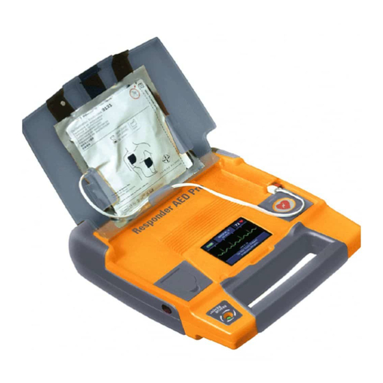
AED PARTS The following drawings show the AED parts and their locations. Battery Compartment RescueReady Status Indicator Latch Electrode Expiration (Push in to open) Window Serial Communication Port (Behind blue rubber data access cover) Electrode Holders Speaker Electrode Connector Diagnostic Panel Text Display SHOCK/CONTINUE Button page 22... - Page 24 Section 3 - Getting Started THE AED HAS THREE MODES: Operating Mode: Defined as having the battery installed and the lid open. This is the mode the AED would be in during an actual rescue situation. Standby Mode: When the battery is installed, but the lid is closed. In this mode the AED is not being used in a rescue.
-
Page 25: Intellisense Battery
Battery Capacity Remaining BATTERY OPERATING LIFE The battery operating life depends on the type of battery (9142 for Responder AED ), actual usage and environmental factors. The following table represents the expected life of the Responder AED when used in Standby Mode. - Page 26 Section 3 - Getting Started BATTERY SHELF LIFE The Responder AED batteries have a shelf-life of five years. Shelf-life is defined as the length of time a bat- tery can be stored, prior to installation into AED, without degrading its performance.
-
Page 27: Electrodes
Keep a fresh, unopened pair of electrodes plugged into the AED at all times. Refer to the electrode package label for operation temperatures. On the Responder AED, an audible and visual alert will indicate after the self-test if the electrodes are missing, unplugged or damaged. -
Page 28: Aed Indicators
Peel and place remaining electrode. AED INDICATORS The following indicators are located on the AED. The STATUS INDICATOR is located on the Responder AED handle. When this indicator is GREEN, the device is RescueReady. This means the Responder AED self-tests have verified the following: •... - Page 29 The ELECTRODES LED lights up when the electrodes are: • Not properly connected to the AED • Not within operational specifications (cold, dried, damaged). This feature applies to the Responder AED only. • Disconnected from the patient during a rescue. page 28 201-9198-001 Rev A...
- Page 30 Section 3 - Getting Started SERVICE INDICATOR The SERVICE LED lights up when the AED requires maintenance that can only be performed by qualified service personnel. SHOCK/CONTINUE BUTTON The AED has one button called the SHOCK/CONTINUE button. This button is located on the diagnostic panel and serves two functions: •...
-
Page 31: Setting The Aed Internal Clock
The voice prompts activate when the AED lid is opened and help guide the operator through the rescue. The Responder AED text display provides a visual display of most of the audible voice prompts. The following table lists the voice and text prompts and a description of when the prompts are issued. - Page 32 Section 3 - Getting Started VOICE PROMPT TEXT DISPLAY SITUATION “Stand Clear! Push STAND CLEAR After the AED is fully charged and ready to deliver the Flashing Button to PUSH BUTTON TO SHOCK defibrillation shock. The RED SHOCK indicator flashes Deliver Shock.”...
- Page 33 VOICE PROMPT TEXT DISPLAY SITUATION “Communications Mode” COMMUNICATIONS MODE When the lid is open and the serial communication cable is plugged into the AED. (Beep) “One Beep” occurs in 15-second intervals during CPR when enabled by the MDLink software program, “Warble Beep”...
-
Page 34: Section 4 - Instructions For Use Overview
Section 4 - Instructions for Use SECTION 4 – INSTRUCTIONS FOR USE OVERVIEW This section presents information about how to use the AED to perform a rescue. Topic Page # Step 1: Assessment and Electrode Placement Step 2: ECG Analysis Step 3: Shock Delivery and CPR Mode Step 4: Post Rescue Warnings... -
Page 35: Step 1: Assessment And Electrode Placement
STEP 1: ASSESSMENT AND ELECTRODE PLACEMENT PREPARATION Determine that the patient is over 8 years of age or weighs more than 55 pounds (25 kg) and exhibits the following: The patient is unresponsive, and The patient is not breathing. Remove clothing from the patient’s chest. Ensure the skin site is clean and dry. Dry the patient’s chest and shave excessive hair if necessary. -
Page 36: Step 2: Ecg Analysis
Section 4 - Instructions for Use When the electrodes are placed, the voice prompt will say “Do Not Touch Patient. Analyzing Rhythm.” If the electrodes are not properly placed or become disconnected at any time during the rescue, the voice prompt “Check Electrodes”... -
Page 37: Step 3: Shock Delivery And Cpr Mode
Start CPR.” Perform CPR if the patient is not responsive and not breathing. During this time-out for CPR, the Responder AED can continue to monitor the patient’s heart rhythm. If the patient’s condition changes and the Responder AED detects a shockable rhythm during the CPR period, the voice prompt will say, “... -
Page 38: Step 4: Post Rescue
CAUTION: Use only Approved Equipment Using batteries, electrodes, cables, or optional equipment other than those approved by General Electric may cause the Responder AED to function improperly during a rescue. CAUTION: Possible Improper AED Performance Using electrodes that are damaged or expired may result in improper AED performance. - Page 39 CAUTION: Serial Communication Cable The AED will not function during a rescue when the serial communication cable is connected to its serial port. When the serial communication cable is connected to the AED during a rescue, the prompt “Remove cable to continue rescue” will be heard until you remove the serial communication cable from the AED CAUTION: Possible Radio Frequency (RF) Susceptibility RF susceptibility from cellular phones, CB radios and FM 2-way radio may cause incorrect rhythm...
-
Page 40: Section 5 - Data Management Overview
Section 5 - Data Management SECTION 5 – DATA MANAGEMENT OVERVIEW The AED is designed for ease of data management and review. The data stored in internal memory can be displayed on the PC screen using the RescueLink software. Topic Page # Recording Rescue Data Review Rescue Data... - Page 41 page 40 201-9198-001 Rev A © 2003 General Electric...
-
Page 42: Section 6 - Maintenance & Troubleshooting Overview
Once a month during the daily self-tests, the AED performs a full charge of the capacitors. During this test the AED monitors the charge time, voltage level and proper discharge function. When the Responder AED requires maintenance, audible and/or visual indicators are activated. By monitoring the visual and audible indicators, the user can be assured that the Responder AED is ready to conduct a rescue. -
Page 43: Indicator Troubleshooting Table
If STATUS INDICATOR remains RED, refer diagnostic panel are lit. to the Responder AED for maintenance. Call GEMS IT Customer Service or your local distributor. CAUTION: Temperature/Humidity/Pressure Extremes Exposing the AED to extreme environmental conditions outside of its operating parameters may compromise the ability of the AED to function properly. -
Page 44: Scheduled Maintenance
DAILY MAINTENANCE Check the STATUS INDICATOR to ensure that it is GREEN. When the indicator is GREEN, the Responder AED is ready for a rescue. If the indicator is RED, refer to the Troubleshooting Table in this chapter. MONTHLY MAINTENANCE Open the AED lid. -
Page 45: Authorized Repair Service
Check the Integrity of the Service Indicator (LED) and Circuitry Immediately after opening the AED lid, press and hold the SHOCK/CONTINUE button and confirm that the SERVICE LED is lit. Release the SHOCK/CONTINUE button. Close the lid. Verify that the STATUS INDICATOR returns to GREEN. Open the lid and confirm that no diagnostic indicators are lit. -
Page 46: Frequently Asked Questions
Section 6 - Maintenance & Troubleshooting FREQUENTLY ASKED QUESTIONS QUESTIONS AND ANSWERS Can I give CPR while the AED is analyzing? No. As with all AEDs, the operator should stop CPR compressions during the analysis phase. Can I transport the victim while the AED is analyzing? No. - Page 47 When I open the lid, why do I get the voice prompt “Data in Memory. Push Flashing Button to Erase Data and Perform Rescue.” How to I get the message to stop occurring? This message occurs when there is a previously stored rescue in the internal memory of the AED. You can clear the message by: Pressing the SHOCK/CONTINUE button to erase the internally stored rescue data OR Retrieving the rescue data with RescueLink and erasing the stored data with RescueLink.
-
Page 48: Section 7 - Technical Data Overview
Section 7 - Technical Data SECTION 7 – TECHNICAL DATA OVERVIEW This section presents technical data about the AED. Topic Page # Parameters Safety and Performance Standards STAR Biphasic Waveform RHYTHMx ECG analysis performance PARAMETERS OPERATION Semi-Automatic (shock advisory) AUDIBLE ALERTS Voice Prompt Maintenance Alert VISIBLE INDICATORS... - Page 49 RESCUE DATA STORAGE Storage Capacity Internal 34 minutes ECG data with event annotation DIMENSIONS Measurement Dimension Height 8 cm (3.3 in) Width 27 cm (10.6 in) Depth 31 cm (12.4 in) WEIGHT Model Weight with Batteries and Electrodes 9300 3.10 kg (6.6 lb) ENVIRONMENTAL OPERATION AND STANDBY CONDITIONS Atmosphere Condition...
- Page 50 5 Years 3 Years up to 290 shocks The battery operating life depends on the type of battery (9142 for Responder AED), actual usage and environmental factors. BATTERIES AND CAPACITOR CHARGE TIMES A new battery typically takes 10 seconds to charge the AED to maximum energy.
-
Page 51: Safety And Performance Standards
AED MODELS 9300 The AED has been designed and manufactured to conform to the highest standards of safety and performance including electromagnetic compatibility (EMC). The Responder AED Model 9300E and electrodes conform to the applicable requirements of the following: CE Marked by TUV Product Services 0123 per the Medical Device Directive 93/42/EEC of... - Page 52 Section 7 - Technical Data EMISSIONS Field Models Standard or Compliance 9300 IEC 55011/CISPR 11, Group 1, Class B Magnetic 9300 ANSI/AAMI DF39, <0.5mT on surface, except for within 5cm of the lid magnet and the speaker IMMUNITY Field Models Standard or Compliance 9300 IEC 61000-4-3, Level X, (20V/m)
-
Page 53: Star Biphasic Waveform
ISTA Procedure 2A STAR BIPHASIC WAVEFORM The waveform generated by the Responder AED is a BIPHASIC TRUNCATED EXPONENTIAL waveform that is compliant with ANSI/AAMI DF2 and DF39. The following is a graph of the waveform voltage as a function of time when the AED is connected to a 50 Ohm resistive load. - Page 54 Section 7 - Technical Data Table A2 - Low Variable Energy (200VE) Waveform into Different Resistive Loads (Typical Values) Patient’s Phase 1 Phase 1 Phase 1 Phase 2 Phase 2 Phase 2 Total Energy Impedance Delivered Delivered Duration Delivered Delivered Duration Delivered (Ohms)
-
Page 55: Rhythmx Ecg Analysis Performance
RHYTHMX ECG ANALYSIS PERFORMANCE The AED RHYTHMx ECG Analysis system analyzes the patient’s ECG and advises you when the AED detects a shockable or non-shockable rhythm. This system makes it possible for a person, with no training in the interpretation of ECG rhythms, to offer defibrillation therapy to victims of sudden cardiac arrest. -
Page 56: Section 8 - Accessories Overview
AED Accessories AED Delivery Systems Software Accessories Education Accessories RESPONDER AEDs Responder AED with text display: biphasic waveform, IntelliSense lithium battery (Model 9142), internal memory, and 1 pair of adult defibrillation electrodes. WITH AED QUICK WITHOUT AED QUICK DESCRIPTION RESOURCE GUIDE KIT... -
Page 57: Aed Delivery Systems
CD-ROM containing manual, RescueLink, and MDLink 201616-001 AED Quick Start Tool Kit CD-ROM AED DELIVERY SYSTEMS 2019199-001 Soft-sided carrying case for Responder AED 2019615-001 Ready Kit: includes nitrile gloves, razor, scissors, towel, 4” gauze, antiseptic wipes, one way filter mask 2019199-005...
Need help?
Do you have a question about the Responder AED and is the answer not in the manual?
Questions and answers